set clock MAZDA MX-5 1997 Factory Repair Manual
[x] Cancel search | Manufacturer: MAZDA, Model Year: 1997, Model line: MX-5, Model: MAZDA MX-5 1997Pages: 514, PDF Size: 17.89 MB
Page 12 of 514
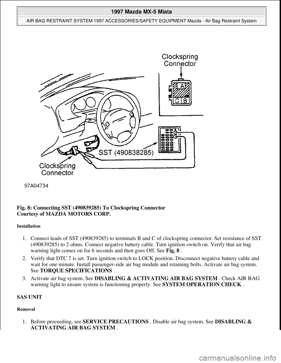
Fig. 8: Connecting SST (490839285) To Clockspring Connector
Courtesy of MAZDA MOTORS CORP.
Installation
1. Connect leads of SST (490839285) to terminals B and C of clockspring connector. Set resistance of SST
(490839285) to 2 ohms. Connect negative battery cable. Turn ignition switch on. Verify that air bag
warning light comes on for 6 seconds and then goes Off. See Fig. 8
.
2. Verify that DTC 7 is set. Turn ignition switch to LOCK position. Disconnect negative battery cable and
wait for one minute. Install passenger-side air bag module and retaining bolts. Activate air bag system.
See TORQUE SPECIFICATIONS
.
3. Activate air bag system. See DISABLING & ACTIVATING AIR BAG SYSTEM
. Check AIR BAG
warning light to ensure system is functioning properly. See SYSTEM OPERATION CHECK
.
SAS UNIT
Removal
1. Before proceeding, see SERVICE PRECAUTIONS . Disable air bag system. See DISABLING &
ACTIVATING AIR BAG SYSTEM.
1997 Mazda MX-5 Miata
AIR BAG RESTRAINT SYSTEM 1997 ACCESSORIES/SAFETY EQUIPMENT Mazda - Air Bag Restraint System
Microsoft
Sunday, July 05, 2009 1:40:47 PMPage 12 © 2005 Mitchell Repair Information Company, LLC.
Page 13 of 514
2. Drain cooling system. Remove dashboard. Remove heater unit. SAS unit connectors. Remove 4 SAS unit
mounting bracket nuts. Remove 2 SAS unit retaining screws. Remove SAS unit. See Fig. 9
.
Installation
To install, reverse removal procedure. Position SAS unit and bracket with arrow toward front of vehicle.
Tighten fasteners to specification. See TORQUE SPECIFICATIONS
. After SAS unit is installed, activate air
bag system. See DISABLING & ACTIVATING AIR BAG SYSTEM
. Check AIR BAG warning light to
ensure system is functioning properly. See SYSTEM OPERATION CHECK
.
CLOCKSPRING
Removal
1. Set front wheels in straight-ahead position. Before proceeding, see SERVICE PRECAUTIONS .
Disable air bag system. See DISABLING & ACTIVATING AIR BAG SYSTEM
.
2. Remove driver-side air bag module. See DRIVER
-SIDE AIR BAG MODULE . Remove steering wheel
nut. Using a puller, remove steering wheel. Remove steering column covers. Remove clockspring screws.
Remove clockspring and combination switch as an assembly.
Installation
1. To install, reverse removal procedure. Tighten steering wheel nut to specification. See TORQUE
SPECIFICATIONS .
2. After installation, activate air bag system. See DISABLING & ACTIVATING AIR BAG SYSTEM
.
Check AIR BAG warning light to ensure system is functioning properly. See SYSTEM OPERATION
CHECK .
SAS UNIT
Removal
1. Before proceeding, see SERVICE PRECAUTIONS . Disable air bag system. See DISABLING &
ACTIVATING AIR BAG SYSTEM .
2. SAS unit is located under center of dashboard. See Fig. 1
. Remove dashboard. Remove heater assembly.
Disconnect SAS unit connectors. Remove 4 SAS unit mounting bracket nuts. Remove 2 SAS unit
retainin
g screws. Remove SAS unit. See Fig. 9. NOTE: Clockspring is part of combination switch. When replacing clockspring, replace
the clockspring and combination switch as an assembly.
1997 Mazda MX-5 Miata
AIR BAG RESTRAINT SYSTEM 1997 ACCESSORIES/SAFETY EQUIPMENT Mazda - Air Bag Restraint System
Microsoft
Sunday, July 05, 2009 1:40:47 PMPage 13 © 2005 Mitchell Repair Information Company, LLC.
Page 18 of 514
Remove driver-side air bag module. See DRIVER-SIDE AIR BAG MODULE under REMOVAL &
INSTALLATION.
2. Inspect clockspring connectors for damage. If connectors are okay, go to next step. If connectors are
damaged, replace clockspring. Perform SYSTEM OPERATION CHECK
.
3. Connect Special Service Tool (49 0839 285) to terminal No. 3B and terminal No. 3C of clockspring. Set
SST resistance to 2 ohms. Connect clockspring connector. Connect negative battery cable. Turn ignition
switch to ON position and cheek for codes. If CODE 6 is displayed, go to next step. If CODE 6 is not
present, replace driver-side air bag module. Perform SYSTEM OPERATION CHECK
.
4. Turn ignition switch to LOCK position. Disconnect negative battery cable and wait for 1 minute.
Disconnect clockspring connector and inspect. If pins are ok go next step. If pins are damaged, replace
wiring harness from clockspring to SAS unit.
5. Connect Special Service Tool (49 0839 285) to terminal No. A and terminal No. B of clockspring
connector. Set SST resistance to 2 ohms. Connect clockspring connector and connect negative battery
cable. Turn ignition switch to ON position and cheek for codes. If CODE 6 is displayed, go to next step.
If CODE 6 is not present, replace clockspring. See CLOCKSPRING
under REMOVAL &
INSTALLATION. Perform SYSTEM OPERATION CHECK
.
6. Turn ignition switch to LOCK position. Disconnect negative battery cable. Wait for 1 minute. Remove
dashboard and heater unit. Disconnect SAS unit connector.
7. Check wiring harness between terminal No. O of SAS unit connector and between terminal No. A of
clockspring connector. Also check between terminal No. M of SAS unit connector and terminal No. B of
clockspring connector. Check for short to ground, short to power or open circuit. If wiring is OK, replace
SAS unit. See SAS UNIT
under REMOVAL & INSTALLATION.If wiring is not OK, replace wiring
harness from clockspring to SAS unit. Perform SYSTEM OPERATION CHECK
.
DTC 7 - PASSENGER-SIDE AIR BAG MODULE
1. Disable air bag system. See DISABLING & ACTIVATING AIR BAG SYSTEM
. Inspect passenger-
side air bag module connectors for damage. If connectors are okay, go to next step. If connectors are
damaged, replace wiring harness from passenger-side air bag module to SAS unit. Perform SYSTEM
OPERATION CHECK .
2. Connect Special Service Tool (49 0839 285) to terminal No A and terminal No. B of passenger-side air
bag module connector. Set Special Service Tool resistance to 2 ohms. Connect clockspring connector.
Connect negative battery cable. Turn ignition switch to ON position and check for codes. If DTC 7 is
displayed, go to next step. If CODE 7 is not present replace passenger-side air bag module. See
PASSENGER
-SIDE AIR BAG MODULE under REMOVAL & INSTALLATION. Perform SYSTEM
OPERATION CHECK .
3. Turn ignition switch to LOCK position. Disconnect negative battery cable and wait 1 minute. Disconnect
clocksprin
g connector. Remove dashboard and heater unit. NOTE: For connector terminal identification, see WIRING DIAGRAM
.
NOTE: When resistance is detected between terminals l-K of SAS unit is NOT 2 ohms
and/or there is no continuity between terminal No. E of SAS unit and ground,
DTC 7 will set
1997 Mazda MX-5 Miata
AIR BAG RESTRAINT SYSTEM 1997 ACCESSORIES/SAFETY EQUIPMENT Mazda - Air Bag Restraint System
Microsoft
Sunday, July 05, 2009 1:40:48 PMPage 18 © 2005 Mitchell Repair Information Company, LLC.
Page 294 of 514
Installation
To install, reverse removal procedure. Fully tighten all bolts with vehicle resting on ground and suspension
unloaded. See TORQUE SPECIFICATIONS
. Check front wheel alignment. See SPECIFICATIONS &
PROCEDURES article in WHEEL ALIGNMENT.
STABILIZER BAR
Removal & Installation
Raise and support vehicle. Remove engine splash shield. Remove frame brackets and bushings. Remove
stabilizer control links. Align bushing with installation mark on stabilizer. Reverse removable procedure for
installation. See TORQUE SPECIFICATIONS
.
FRONT STRUT BAR (1999)
Removal & Installation
1. To remove strut bar located in engine compartment mounted on top of shock towers, loosen lock nuts on
joint bolt and loosen joint bolt. Remove nut, washer and bolt retaining strut bar to strut plate. Remove
strut bar from vehicle.
2. To install, reverse removal procedure. Rotate joint bolt counterclockwise to 3.5-5.2 INCH lbs. (.4-.6 N.m)
to set tension. Tighten lock nuts to 87-121 INCH lbs. (10-14 N.m). Tighten strut bar-to-strut plate nut.
See TORQUE SPECIFICATIONS
.
TORQUE SPECIFICATIONS
TORQUE SPECIFICATIONS
ApplicationFt. Lbs. (N.m)
Axle Lock Nut123-159 (167-215)
Brake Caliper Bracket Bolts37-50 (50-68)
Lower Ball Joint-To-Knuckle Nut42-57 (57-77)
Lower Ball Joint-To-Lower Control
199754-69 (73-94)
1999 & 2000
Bolt & Nut69-86 (94-117)
Bolt54-69 (73-94)
Lower Control Arm-To-Frame
1997
Front Adjusting Bolt Lock Nut69-83 (94-112)
Rear Adjusting Bolt Lock Nut62-75 (84-102)
1999 & 200069-83 (94-112)
Shock Assembly-To-Lower Control Arm Bolt/Nut
199754-68 (73-93)
1997 Mazda MX-5 Miata
1997-2000 SUSPENSION Front - Miata
Microsoft
Sunday, July 05, 2009 1:38:08 PMPage 7 © 2005 Mitchell Repair Information Company, LLC.
Page 331 of 514
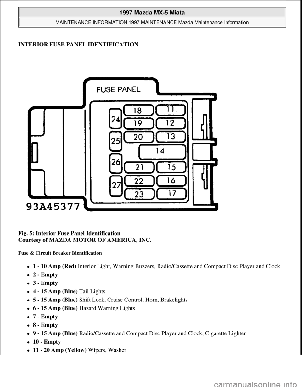
INTERIOR FUSE PANEL IDENTIFICATION
Fig. 5: Interior Fuse Panel Identification
Courtesy of MAZDA MOTOR OF AMERICA, INC.
Fuse & Circuit Breaker Identification
1 - 10 Amp (Red) Interior Light, Warning Buzzers, Radio/Cassette and Compact Disc Player and Clock
2 - Empty
3 - Empty
4 - 15 Amp (Blue) Tail Lights
5 - 15 Amp (Blue) Shift Lock, Cruise Control, Horn, Brakelights
6 - 15 Amp (Blue) Hazard Warning Lights
7 - Empty
8 - Empty
9 - 15 Amp (Blue) Radio/Cassette and Compact Disc Player and Clock, Cigarette Lighter
10 - Empty
11 - 20 Amp (Yellow) Wipers, Washer
1997 Mazda MX-5 Miata
MAINTENANCE INFORMATION 1997 MAINTENANCE Mazda Maintenance Information
Microsoft
Sunday, July 05, 2009 1:41:19 PMPage 11 © 2005 Mitchell Repair Information Company, LLC.
Page 403 of 514
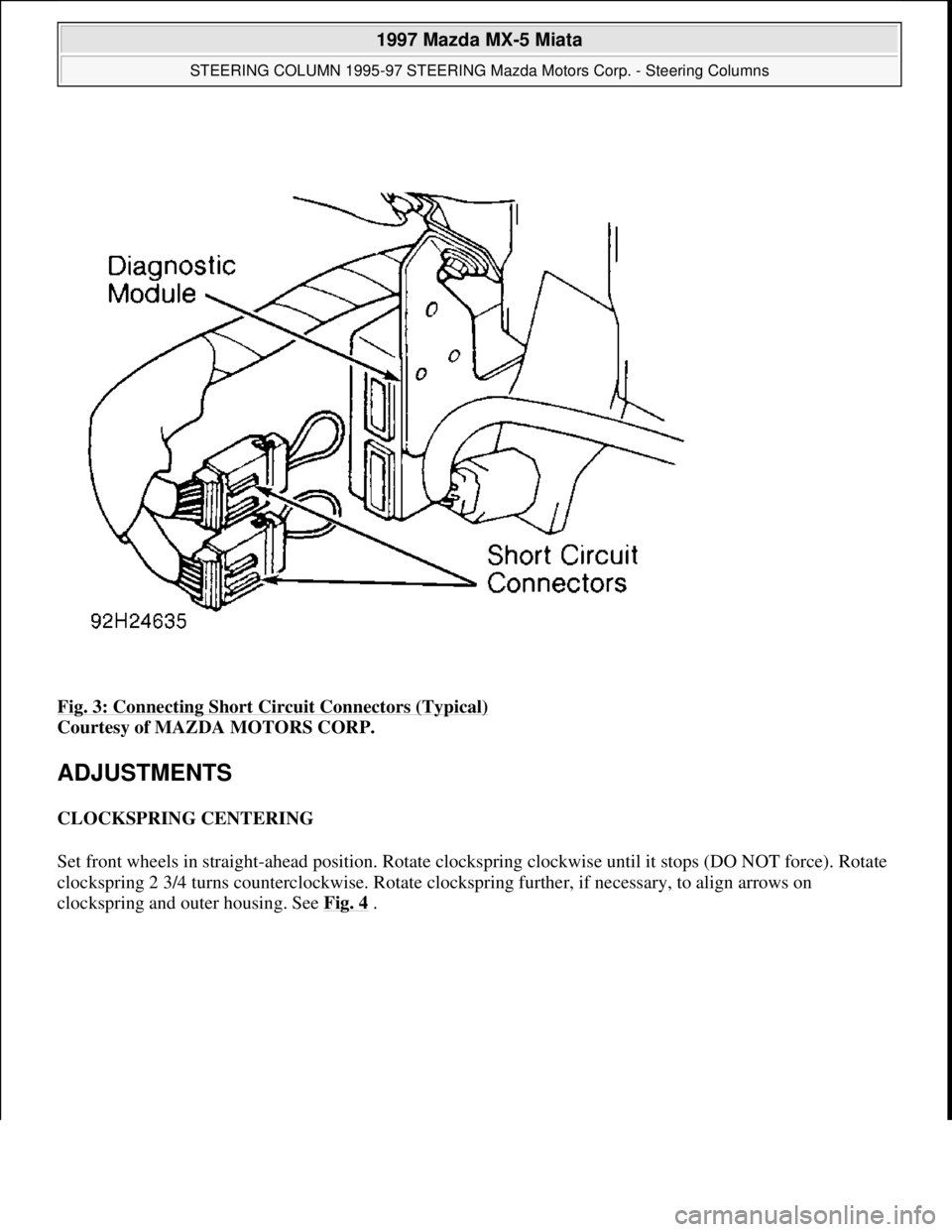
Fig. 3: Connecting Short Circuit Connectors (Typical)
Courtesy of MAZDA MOTORS CORP.
ADJUSTMENTS
CLOCKSPRING CENTERING
Set front wheels in straight-ahead position. Rotate clockspring clockwise until it stops (DO NOT force). Rotate
clockspring 2 3/4 turns counterclockwise. Rotate clockspring further, if necessary, to align arrows on
clocksprin
g and outer housing. See Fig. 4 .
1997 Mazda MX-5 Miata
STEERING COLUMN 1995-97 STEERING Mazda Motors Corp. - Steering Columns
Microsoft
Sunday, July 05, 2009 1:40:02 PMPage 5 © 2005 Mitchell Repair Information Company, LLC.
Page 405 of 514
To install, reverse removal procedure. Tighten driver air bag module bolts or nuts to specification. See
TORQUE SPECIFICATIONS
table. Activate air bag system. See AIR BAG DISABLING &
ACTIVATING . Check AIR BAG warning light to ensure system is functioning properly. See SYSTEM
OPERATION CHECK .
STEERING WHEEL
Removal
Set front wheels in straight-ahead position. Disconnect negative battery cable. Disable air bag system. See AIR
BAG DISABLING & ACTIVATING . Remove driver air bag module. See DRIVER AIR BAG MODULE .
Mark steering wheel and shaft for reassembly reference. Remove steering wheel nut. Using appropriate puller,
remove steering wheel.
Installation
Ensure front wheels are in straight-ahead position. Install steering wheel, ensuring reference marks are aligned.
Tighten steering wheel nut to specification. See TORQUE SPECIFICATIONS
table. To install remaining
components, reverse removal procedure.
COMBINATION SWITCH
Removal
1. Before proceeding, follow air bag service precautions. See SERVICE PRECAUTIONS. Disable air bag
system. See AIR BAG DISABLING & ACTIVATING
.
2. Remove driver air bag module. See DRIVER AIR BAG MODULE
. Remove steering wheel. See
STEERING WHEEL
. Remove upper and lower steering column covers. Disconnect combination
switch electrical connectors. Remove combination switch screws.
3. Remove clockspring and combination switch as an assembly. Separate clockspring from combination
switch.
Installation
1. To install, reverse removal procedure. Ensure front wheels are in straight-ahead position. Before
installing steering wheel, center clockspring. See CLOCKSPRING CENTERING
under
ADJUSTMENTS. Tighten steering wheel nut to specification. See TORQUE SPECIFICATIONS
table.
2. After installation, activate air bag system. See AIR BAG DISABLING & ACTIVATING
. Check AIR
BAG warning light to ensure system is functioning properly. See SYSTEM OPERATION CHECK
.
IGNITION SWITCH/STEERING LOCK ASSEMBLY
Removal & Installation
1. Remove driver air bag module, steering wheel and combination switch. See the following:
DRIVER AIR BAG MODULE.
1997 Mazda MX-5 Miata
STEERING COLUMN 1995-97 STEERING Mazda Motors Corp. - Steering Columns
Microsoft
Sunday, July 05, 2009 1:40:02 PMPage 7 © 2005 Mitchell Repair Information Company, LLC.