fuel type MAZDA PROTEGE 1992 Workshop Manual
[x] Cancel search | Manufacturer: MAZDA, Model Year: 1992, Model line: PROTEGE, Model: MAZDA PROTEGE 1992Pages: 1164, PDF Size: 81.9 MB
Page 33 of 1164
OUTLINE, TROUBLESHOOTING GUIDE Bl
OUTLINE
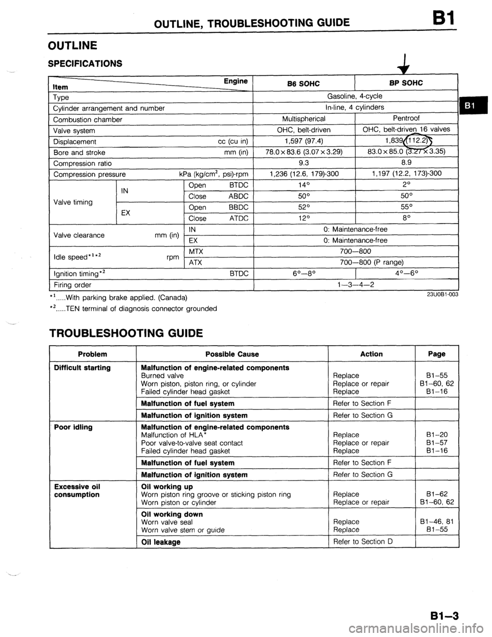
SPECIFICATIONS
item Engine
Type
Cylinder arrangement and number
Combustion chamber
Valve system
Displacement cc (cu in)
Bore and stroke mm (in)
Compression ratio
Compression pressure
kPa (kg/cm2, psi)-rpm
Open BTDC
IN
Close ABDC
Valve timing
EX Open
BBDC
Close ATDC
IN
Valve clearance
mm (in)
EX
Idle speed*‘*’ MTX
rpm ATX
Ignition timing*2
BTDC
Firing order
*‘.....With parking brake applied. (Canada)
*‘.....TEN terminal of diagnosis connector grounded B6 SOHC BP SOHC
Gasoline, 4-cycle
in-line, 4 cylinders
Multispherical Pentroof
OHC, belt-driven OHC, belt-driven 16 valves
1,597 (97.4) 1,839&i 12.23
78.0 x 83.6 (3.07 x 3.29) 83.0x 85.0 -3.35)
9.3 8.9
1,236 (12.6, 179)300 1,197 (12.2, 173)-300
140 2O
50° 5o”
52O 55O
120 8
0: Maintenance-free
0: Maintenance-free
700-800
700-800 (P range)
6O----8O 4O--6O
1-3-4-2
23UOBl-003
TROUBLESHOOTING GUIDE
Problem
Difficult starting
Poor idling
Excessive oil
consumption Possible Cause
Malfunction of engine-related components
Burned valve
Worn piston, piston ring, or cylinder
Failed cvlinder head aasket Action Page
Replace 81-55
Replace or repair 81-60, 62
Reolace Bl-16
Malfunction of fuel system
1 Refer to Section F
I
Malfunction of ignition system
Malfunction of engine-related components
Malfunction of HLA*
Poor valve-to-valve seat contact
Failed cvlinder head aasket Refer to Section G
Replace
Replace or repair
Reolace 81-20
81-57
81-16
Malfunction of fuel system 1 Refer to Section F
I
Malfunction of ignition system Refer to Section G
Oil working up
Worn piston ring groove or sticking piston ring
Worn piston or cylinder
Oil working down
Worn valve seal
Worn valve stem or wide Replace
Replace or repair
Replace
Replace 81-62
Bl-60, 62
81-46, 81
81-55
Oil leakage Refer to Section D
81-3
Page 135 of 1164

OUTLINE, TROUBLESHOOTING GUIDE
OUTLINE
SPECIFICATIONS
ItC- Engine
BP DOHC
Type Gasoline, 4-cycle
Cylinder arrangement and number In-line, 4 cylinders
Combustion chamber Pentroof
Valve svstem DOHC, belt-driven 16 valves
Displacement
Bore and stroke cc (cu in) 1,839 (112.2)
mm (in) I 83.0 x 85.0 (3.27 x 3.35)
Compression ratio
Compression pressure
IN
Valve timing
EX kPa (kg/cm*, psi)-rpm
BTDC Open
Close ABDC
Open BBDC
Close ATDC 9.0
1,256 (12.8, 182)300
!zJ”
48O
56O
140
Valve clearance IN 0: Maintenance-free
mm (in)
EX 0: Marntenance-free
Idle speed *’ *’ MTX
rpm
ATX
Ignition timing*2
Firing order
::...With parking brake applied. (Canada)
. ..TEN terminal of diagnosis connector grounded BTDC 700-800
700-800 (P range)
90-l 1 O
l-3-4-2
P3UOBZ003
TROUBLESHOOTING GUIDE
Problem
Difficult starting
Poor idling
Excessive oil
consumption Possible Cause
Malfunction of engine-related components
Burned valve
Worn piston, piston ring, or cylinder
Failed cylinder head gasket
Malfunction of fuel system
Malfunction of ignition system
Malfunction of engine-related components
Malfunction of HLA*
Poor valve-to-valve seat contact
Failed cylinder head gasket
Malfunction of fuel system
Malfunction of ignition system
Oil working up
Worn piston ring groove or sticking piston ring
Worn oiston or cvlinder
Oil working down
Worn valve seal
Worn valve stem or auide
Oil leakaae i
Replace 82-55
Replace or repair 92-60, 62
Reolace B2-16
Refer to Section F
I
Replace 82-47, 79
Replace 82-55
Refer to Section 0 I
82-3
Page 281 of 1164
OUTLINE F
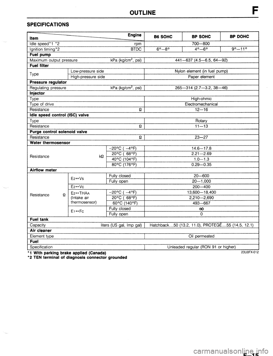
SPECIFICATIONS
Item
Idle speed*1 *2
Ignition timing*2
Fuel pump
Maximum outout Dressure Engine
rpm B6 SOHC
6O--80 BTDC 1
kPa (ka/cm’. osi1 1 BP SOHC
700-800
4O---6O BP DOHC
90-l 1 O
441-637 (4.5-6.5. 64-92) I
I Fuel filter I
Type Low-pressure side Nylon element (in fuel pump)
High-pressure side Paper element
Pressure reaulator
Regulating pressure kPa (kg/cm’, psi) 1 265-314 (2.7-3.2, 38-46)
I lniector I
Type Type of drive
Resistance
Idle speed control (ISC) valve
TvDe , ,
t Resistance
Purge control solenoid valve
Resistance
Water thermosensor n High-ohmic
Electromechanical
12-16
Rotarv
n I II-13 I
n 1 23-27
1 -20% I -4OFj 1 14.6-17.8
Resistance k62 2ooc i 68OF) 2.21-2.69
40°C (104OF) 1.0-l .3
80°C (176OF) 0.29-0.35
Airflow meter
E2++Vs
E2-Vc Fully closed
Fully open 20-600
20-l ,000
200-400
Capacity liters (US gal, Imp gal) 1 Hatchback 50 (13.2, ll.O), PROTEGE ,... 55 (14.5, 12.1)
I Air cleaner I
Element type
Fuel
Specification l
l Wlth parking brake applied (Canada)
‘2 TEN terminal of diagnosis connector grounded Oil permeated
Unleaded regular (RON 91 or higher) 23UOFX-012
F-l 5
Page 282 of 1164
F OUTLINE
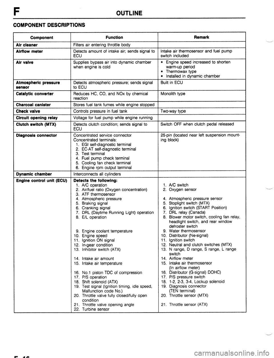
COMPONENT DESCRIPTIONS
Component
Air cleaner
Airflow meter
Mr valve
Atmospheric pressure
Sensor
Catalytic converter Function Remark
Filters air entering throttle body
Detects amount of intake air; sends signal to intake air thermosensor and fuel pump
ECU switch included
Supplies bypass air into dynamic chamber
l Engine speed increased to shorten
when engine is cold warm-up period
l Thermowax type l Installed in dynamic chamber
Detects atmospheric pressure; sends signal Built in ECU
to ECU
Reduces HC, CO, and NOx by chemical Monolith type
reaction Charcoal canister
Stores fuel tank fumes while engine stopped Check valve
Controls pressure in fuel tank Two-way type Circuit opening relay
Voltage for fuel pump while engine running Clutch switch (MTX)
Detects clutch condition; sends signal to Switch OFF when clutch pedal released
ECU Diagnosis connector
Concentrated service connector 25pin (located near left suspension mount-
Concentrated terminals: ing block)
1. EGI self-diagnostic terminal
2. EC-AT self-diagnostic terminal
3. Test terminal
4. Fuel pump check terminal
5. Cooling fan check terminal
6. Engine rpm output terminal Dynamic chamber
Interconnects all cylinders Engine control unit (ECU) Detects the following:
1. A/C operation 1. A/C switch
2. Air/fuel ratio (Oxygen concentration) 2. Oxygen sensor
3. ATF thermosensor
4. Atmospheric pressure 4. Atmospheric pressure sensor
5. Braking signal 5. Stoplight switch (MTX)
6. Cranking signal 6. Ignition switch (START Position)
7. DRL (Daytime Running Light) operation 7. DRL relay (Canada)
8. E/L operation 8. Blower motor switch, cooling fan relay,
headlight switch, and rear window
defroster switch
9. Engine coolant temperature 9. Water thermosensor
10. Engine speed 10. Distributor (Ne-signal)
11. Ignition ON signal 11. Ignition switch
12. In-gear condition 12. Neutral and clutch switches (MTX)
13. Inhibitor switch (ATX) 13. N range, D range, S range, L range
switch
14. Intake air amount 14. Airflow meter
15. Intake air temperature 15. Intake air thermosensor
(In airflow meter)
16. No.1 piston TDC of compression
17. P/S operation
18. Shift solenoid (ATX)
19. Test signal (Ignition timing, idle speed,
Malfunction code No.)
20. Throttle valve fully closed/fully open
condition 16. Distributor (G-signal) DOHC)
17. P/S pressure switch
18. 1-2, 2-3, 3-4, Lockup solenoid
19. Diagnosis connector
(TEN terminal)
20. Throttle sensor (MTX)
21. Throttle valve opening angle
22. Turbine sensor 21. Throttle sensor (ATX) .__r
F-10
Page 710 of 1164
R OUTLINE
OUTLINE
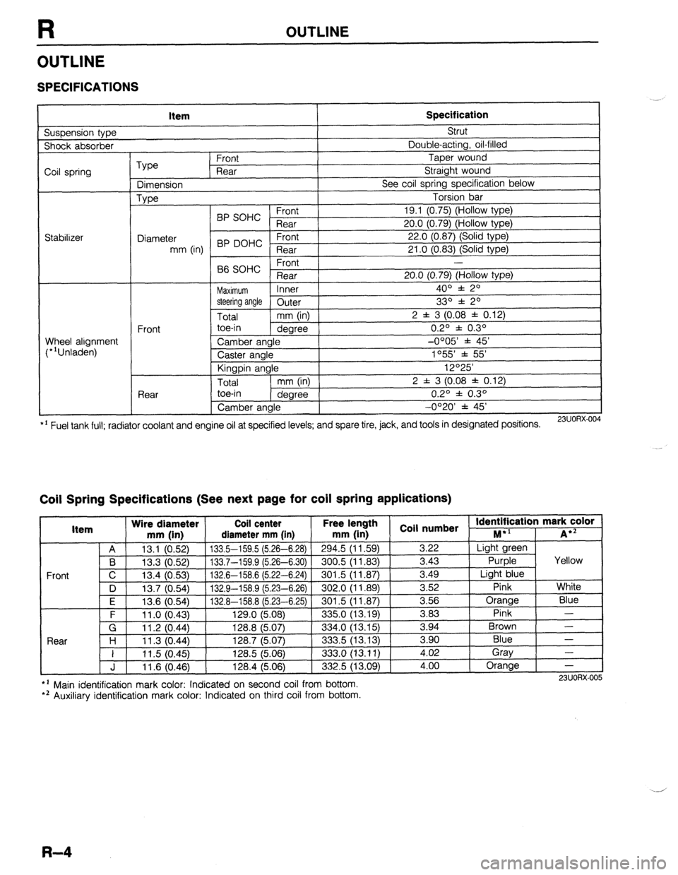
SPECIFICATIONS
Suspension type Item Specification Strut
Shock absorber Double-acting, oil-filled
Coil spring
Stabilizer Type Front Taper wound
Rear Straight wound
Dimension See coil spring specification below
Type Torsion bar
BP SOHC Front 19.1 (0.75) (Hollow type)
Rear 20.0 (0.79) (Hollow type)
Diameter 22.0 (0.87) (Solid type)
mm (in) BP DOHC ;eTrt
21 .O (0.83) (Solid type)
P ,
-
66 SOHC rronr
Rear 20.0 (0.79) (Hollow type)
Maximum Inner 400 f 20
steering angle
Outer 330 f 20
Total mm (in) 2 f 3 (0.08 f 0.12)
Front toe-in
degree 0.2O f 0.3O
Wheel alignment
(*‘Unladen) Camber angle -0005’ f 45’
Caster angle 1055 * 55’
Kingpin angle 12O25’
Total mm (in) 2 f 3 (0.08 * 0.12)
Rear toe-in
degree 0.2O f 0.3O
Camber angle -0°20’ f 45’
*’ Fuel tank full; radiator coolant and engine oil at specified levels; and spare tire, jack, and tools in designated positions.
23UORX.004
Coil Spring Specifications (See next page for coil spring applications)
I Item Wire diameter Coil center Free lel.=-. .
mm iin1 rliamotor mm [in mm (in 1 coil numbs
Front
nath
1 _ . . *St Identification mark color +l
., . . . . I...,
-*.....-.“, * . . . . . ,..-, -....- I--‘, M iA*=
A 13.1 (0.52) 133.5-159.5 (5.26-6.28)
294.5 (11.59) 3.22 Light green
B 13.3 (0.52) 133.7-159.9 (5.26-6.30) 300.5 (11.83)
3.43 Purple Yellow
C 13.4 (0.53)
132.6-158.6 (5.22-6.24) 301.5 (11.87) 3.49
Light blue
D 13.7 (0.54)
132.9-158.9 (5.23-6.26) 302.0 (11.89) 3.52
Pink White
I F I 12f3 Kl5Al I 1.17 A-l!% 8 f!i PR-Fi 751
I RrIl .5 II 1 6x71 I 3.56 Orange
Blue
3 83 Pink -
Brown - .“._ \“.- .,
. “W.., ~ - -. - \-. -- -. - -, -- .-
\’ .‘-‘I t
F 11 .o (0.43) 129.0 (5.08)
335.0 (13.19) -.--
G 11.2 (0.44) 128.8 (5.07)
334.0 (13.15) 3.94
Rnnr l-4
1 I ? 07 AA 1387 /5n7
.?m !i 113 1% 3 an Blue - I I I I .” \v.-7, I&V., \V.“., ---.., \.-. .-, I 11.5 (0.45) 128.5 (5.06)
333.0 (13.11) i:oi Gray
-
J 11.6 (0.46) 128.4 (5.06)
332.5 (13.09) 4.00 Orange
-
l ’ Main identification mark color: Indicated on second coil from bottom.
*’ Auxiliary identification mark color: Indicated on third coil from bottom. 23UORX-005
R-4
Page 1023 of 1164
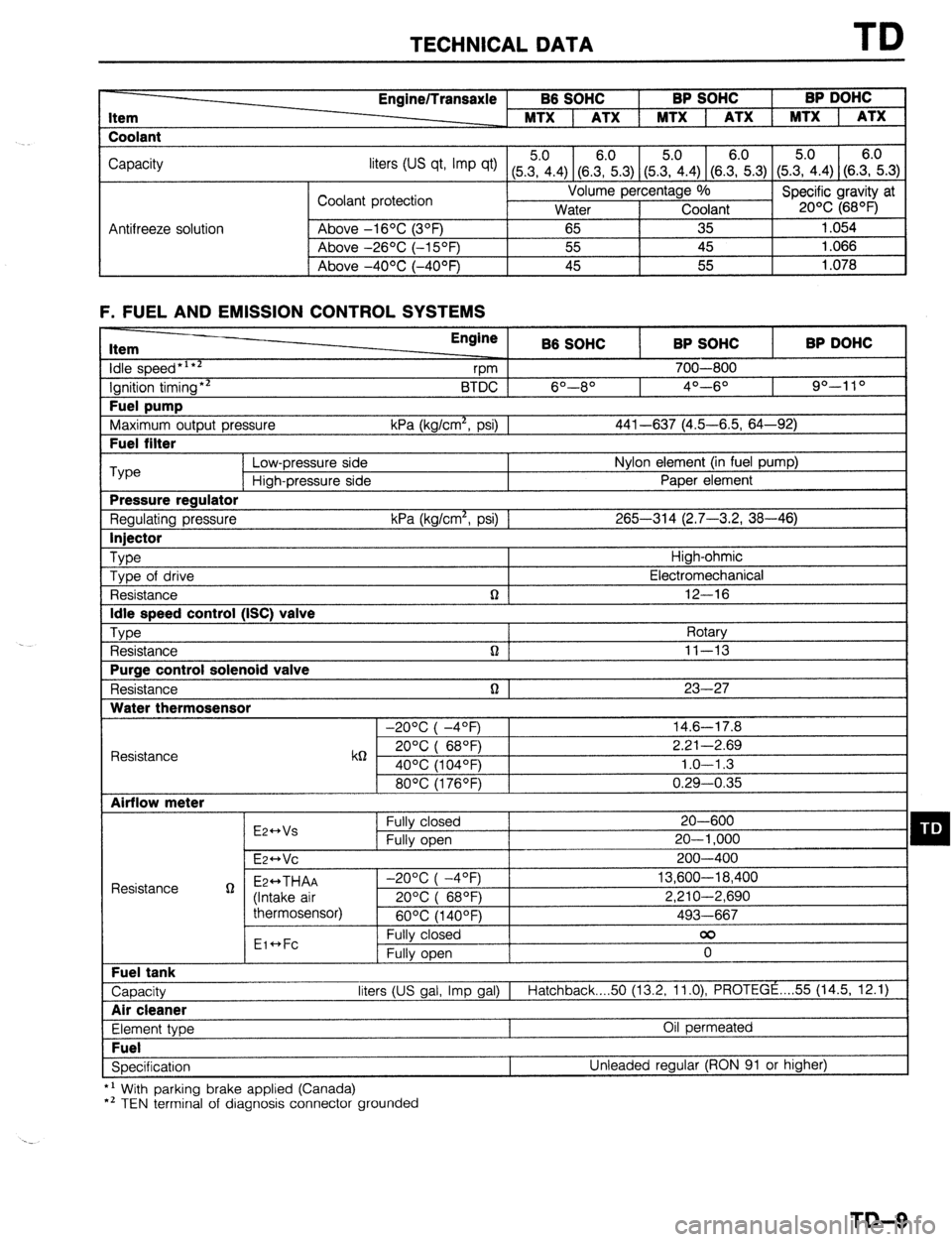
TECHNICAL DATA TD
Item
Coolant Engine/Transaxle B6 SOHC BP SOHC BP DOHC
MTX 1 ATX 1 MTX 1 ATX 1 MTX 1 ATX
Capacity
liters tus qt, Imp qt) (5Z.4) (8.E.3) (5&4) (SE.3) (5.?i.4) (S.E.3)
Coolant protection Volume percentage %
Specific gravity at
Water Coolant 20% (68OF)
Antifreeze solution Above -16OC (3OF)
65 35 1.054
Above -26OC (-15OF) 55 45 1.066
I Above -4OOC (-40°F) 45 55
1.078
F. FUEL AND EMISSION CONTROL SYSTEMS Item
idle speed*‘**
Ignition timing** Fuel pump
Maximum output pressure Fuel filter Engine
B6 SOHC BP SOHC BP DOHC
vm 700-800
BTDC 6O--8O 4O---6O 90-l 10
kPa (kg/cm*, psi) 1 441-637 (4.5-6.5, 64-92) ‘Type
Low-pressure side Nylon element (in fuel pump)
High-pressure side Paper element Pressure regulator
Regulating pressure kPa (kg/cm*, psi) 1 265-314 (2.7-3.2, 38-46) Injector
Type
High-ohmic
Type of drive Electromechanical
Resistance n 12-16 Idle speed control (ISC) valve
Type
Rotary
Resistance n ] 11-13 Purge control solenoid valve
Resistance n 1 23-27 Water thermosensor
-20°C( -4OF) 14.6-17.8
Resistance k6 20°C( 68QF) 2.21-2.69
40% (104OF) 1.0-l .3
80°C(1760F) 0.29-0.35 Airflow meter
E2++Vs Fully closed 20-600 q D Fully open 20-l ,000
E~HVC 200-400
Resistance g Ez++THAA -2O%(-4OF) 13,600-18,400
(Intake air 20%( 68OF) 2,210-2,690
thermosensor)
60°C(1400F) 493-667
Eic*Fc Fully closed 00
Fully open 0 Fuel tank
Capacity liters (US gal, Imp gal) I
Hatchback 50 (13.2, 11.0) PROTEGE . . . . 55 (14.5, 12.1) Air cleaner
Element type Oil permeated Fuel
Specification Unleaded regular (RON 91 or higher)
*’ With parking brake applied (Canada)
*’ TEN terminal of diagnosis connector grounded
TD-9
Page 1033 of 1164

TECHNICAL DATA
Q. WHEELS AND TIRES
Item Specifications
Wheel
Size
Off set Standard: 13x5-J, 14x5 l/2-JJ
Temporary
mm (in) 1 _ spare: 14x4-T
45 (1.77)
I Diameter of oitch circle
mm (in) I 100 (3.94)
r I Pl
-
Inflation pressure kPa (kg/cm*, psi) Front 1 8
I 9
Runout limit
Unbalance limit mm (in) ;lii.raltLa’
a (02) ’
13 inch wheel: 11 (0.
R. SUSPENSION Item Specifications
Suspension type Strut
)e Double-acting, oil-filled
I Shock absorber tyf
Coil spring
Type
Dimension
Type Front Taper wound
Rear Straight wound
See next page
Torsion bar
I
I C.rrn,
19.1 (0.75)
20.0 (0.79)
22.0 (0.87)
21 .O f0.83)
Wheel alignment
(“‘Unladened) BP SOHC ;;a;
Diameter
mm (in) BP DOHC - ;la;t
Front -
B6 SOHC
Rear 20.0 (0.79)
Maximum Inner 4o” f 2O
steering angle Outer
Total mm (in) 2 f 3 (0.08 j
Front toe-in
dearee
.-.._
Rear
.--. I --- ~~
Camber angle
Caster angle
Kingpin angle
I Total
I mm OnI I I toe-in
1 dearee I , --U’-- 1
Camber angle
I 33O * 2O
: 0.12)
0.2O f 0.3O
-0OO5’ * 45’
1055’ * 55’
12O25’
2 f 3 (0.08 f 0.12)
0.2O f 0.3O
-0°20’ f 45’
l ’ Fuel tank full; radiator coolant and engine ail at specified level; and spare tire, jack, and tools in designated posmons.
TD-19