automatic transmission MERCEDES-BENZ A-CLASS HATCHBACK 2018 Owner's Guide
[x] Cancel search | Manufacturer: MERCEDES-BENZ, Model Year: 2018, Model line: A-CLASS HATCHBACK, Model: MERCEDES-BENZ A-CLASS HATCHBACK 2018Pages: 609, PDF Size: 10.73 MB
Page 456 of 609
To
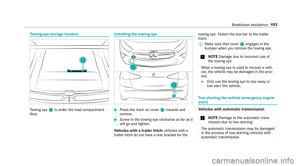
wing eyesto rage location To
wing eye1 is under the load compartment
fl oor. Installing
theto wing eye #
Press the mark on co ver1 inwa rds and
re mo ve. #
Screw intheto wing eyeclockwise as far as it
will go and tighten.
Ve hicles with a trailer hitch: vehicles with a
trailer hitch do not ha veare ar brac ketfo rthe to
wing eye. Fasten theto w bar tothe trailer
hitch.
% Make sure that co ver1 engages in the
bumper when youre mo vetheto wing eye.
* NO
TEDama gedue toincor rect use of
th eto wing eye When a
towing eye is used toreco ver a vehi‐
cle, theve hicle may be damaged in the proc‐
ess. #
Only use theto wing eyeto to waw ay or
to w start theve hicle. To
w starting theve hicle (eme rgency engine
st art) Ve
hicles with automatic transmission
* NO
TEDama getothe automatic trans‐
mission due to tow-starting The automatic transmission may be damaged
in the process of tow- starting vehicles with
automatic transmission. Breakdown assis
tance 453
Page 457 of 609
#
Vehicles with automatic transmission
must not be tow- star ted. #
Vehicles with automatic transmission must
not be tow- star ted.
Ve hicles with manual transmission #
Obser vethe no tes on towing away
( → page 450). #
If necessar y,allow the engine and exhaust
sy stem tocool down. #
Switch the ignition on. #
Enga gesecond gear. #
Release the electric parking brake. #
Tow- start theve hicle while the clutch pedal
is fully depressed. #
Slowly release the clutch pedal. #
Immediately shift toneutral if the engine
st arts. #
Pull over and stop theve hicle, paying atten‐
tion toroad and traf fic conditions. #
Remo vetheto w bar. #
Remo vetheto wing eye. #
Have theve hicle checked at a qualified spe‐
cialist workshop. Electrical fuses
Note
s on electrical fuses &
WARNING Risk of accident and inju ry
due to ov erloaded lines
If yo u manipulate or bridge a faulty fuse or if
yo ure place it with a fuse with a higher
amperage, the electric line could be overloa‐
ded.
This could result in a fire. #
Alw aysre place faulty fuses with speci‐
fi ed new fuses conta iningthe cor rect
amperage. *
NO
TEDama gedue toincor rect fuses Electrical components or sy
stems may be
damaged byincor rect fuses, or their func‐
tionality may be significant lyimpaired. #
Only use fuses that ha vebeen appr oved
by Mercedes-Benz and which ha vethe
cor rect fuse rating. Blown fuses mu
stbe replaced with fuses of the
same rating, which you can recognise bythe col‐
our and fuse rating. The fuse ratings and fu rther
information tobe obser ved are lis ted in the fuse
assignment diagram.
Fu se assignment diag ram: onthe fuse box in
th e engine compartment (→ page 455).
* NO
TEDama geor malfunctions caused
by moisture Moisture may cause dama
getothe electrical
sy stem or cause it tomalfunction. #
When the fuse box is open, make sure
th at no moisture can enter the fuse
box. #
When closing the fuse box, make sure
th at the seal of the lid is positioned cor‐
re ctly on the fuse box. 454
Breakdown assis tance
Page 475 of 609
%
The jack weighs appr oximately 3.4 kg.
The maximum load capacity of the jack can
be found on thest icke r af fixe dto the jac k.
The jack is maintenance-free. If there is a
malfunction, please conta ct aqualified spe‐
cialist workshop.
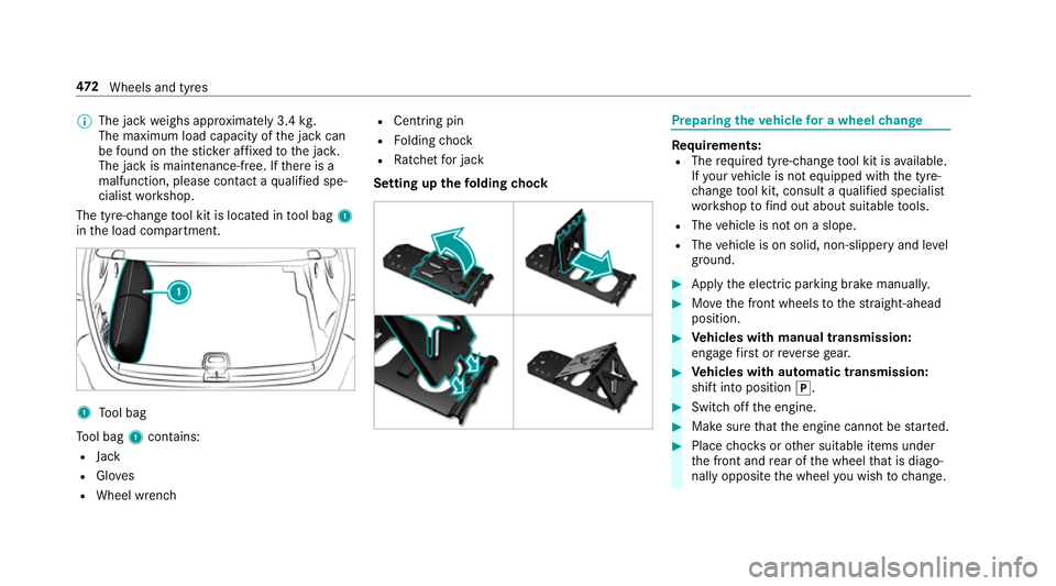
The tyre-change tool kit is located in tool bag 1
in the load compartment. 1
Tool bag
To ol bag 1contains:
R Jack
R Gloves
R Wheel wrench R
Centring pin
R Folding chock
R Ratchet for jack
Setting up thefo lding chock Prepa
ring theve hicle for a wheel change Re
quirements:
R The requ ired tyre-change tool kit is available.
If yo ur vehicle is not equipped with the tyre-
ch ange tool kit, consult a qualified specialist
wo rkshop tofind out about suitable tools.
R The vehicle is not on a slope.
R The vehicle is on solid, non-slippery and le vel
ground. #
Apply the electric parking brake manually. #
Movethe front wheels tothest ra ight-ahead
position. #
Vehicles with manual transmission:
engage firs t or reve rsege ar. #
Vehicles with automatic transmission:
shift into position j. #
Switch off the engine. #
Make sure that the engine cann otbe star ted. #
Place choc ks orother suitable items under
th e front and rear of the wheel that is diago‐
nally opposite the wheel you wish tochange. 472
Wheels and tyres
Page 499 of 609
The
overhang dimension and fastening points
are valid for a trailer hitch ins talled at thefa c‐
to ry.
Missing values werenot available at the time of
going topress. Model
2
2Over‐
hang dimen‐ sion
All models Pe
rm issible towing capacity The
tongue weight is not included in theto wing
capacity. Pe
rm issible towing capacit y,braked (at a
minimum start-off gradeability of 8% from a
st andstill) Model
Perm issible towing
capacit y,braked
A 16 01 500kg
A 180
A 18 0 d 16
00 kg
A 220 4MATIC
A 250 4MATIC 2000
kg
All other models 1800 kg Pe
rm issible towing capacit y,braked (at a
minimum start-off gradeability of 12% from a
st andstill) Model
Perm issible towing
capacit y,braked
A 16 01 300kg
A 180
A 18 0 d 14
00 kg Model
Perm issible towing
capacit y,braked
A 220 4MATIC
A 250 4MATIC 18
00 kg
All other models 1600 kg Pe
rm issible towing capacit y,unbraked Model
Perm issible towing
capacit y,unbraked
A 16 06 65kg
A 18 0 (au tomatic
transmission) 67
5kg
A 18 0d7 05kg
A 18 0 (manual trans‐
mission)
A 200 (manual trans‐
mission) 67
0kg
A 200 (automatic
transmission) 680
kg 496
Tech nical da ta
Page 538 of 609
Ve
hicle Display messages
Possible causes/consequences and M
MSolutions
Transmission Malfunction
Stop *
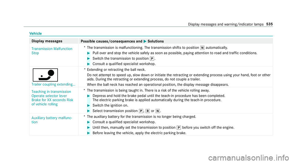
The transmission is malfunctioning. The transmission shifts toposition iautomaticall y. #
Pull over and stop theve hicle safely as soon as possible, paying attention toroad and traf fic conditions. #
Switch the transmission toposition j. #
Consult a qualified specialist workshop.
ï Trailer coupling extending… *E
xtending or retracting the ball nec k.
Do not attem pttospeed up, slow down or initiate there tracting or extending process using your hand, foot or other
aids. During there tracting or extending process, do not couple a traile r.
When the ball neck has reached an operational position, the display message disappears.
Teaching in transmission
Operate selector lever
Brake for XX seconds Risk
of vehicle rolling *T
he transmission is being taught in. There is a risk of theve hicle rolling away. #
Dep ress and hold the brake pedal until thete ach-in procedure has been comple ted.
The elect ric pa rking brake is applied automatically during thete ach-in procedure. #
Swit chthe ignition on. #
Select transmission position j,kori.
Auxiliary battery malfunc-
tion *T
he auxiliary batteryforth e transmission is no longer being charge d. #
Consult a qualified specialist workshop. #
Untilthen, manually set the transmission toposition jbefore you swit choff the engine. #
Before leaving theve hicle, apply the electric parking brake. Display messages and
warning/indicator lamps 535
Page 542 of 609
Display messages
Possible causes/consequences and M
MSolutions #
Depress the clutch pedal again.
The engine starts automaticall y. #
Slowly release the clutch pedal topull away.
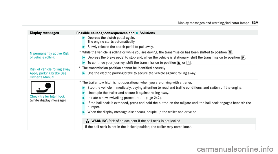
N permanently active Risk
of vehicle rolling *
While theve hicle is rolling or while you are driving, the transmission has been shif tedto position i. #
Depress the brake pedal tostop and, when theve hicle is stationar y,shift the transmission toposition j. #
Tocontinue your journe y,shift the transmission toposition hork.
Risk of vehicle rolling away
Apply parking brake See
Owner's Manual *T
he transmission position cannot be identified securel y. #
Use the electric parking brake tosecure theve hicle against rolling away.
ï
Check trailer hitch lock
(white displ aymessa ge) *T
he trailer tow hit chis not operational when you are driving with a trailer. #
Stop theve hicle immediately, paying attention toroad and traf fic conditions, and switch off the engine. #
Uncouple the trailer and secure it against rolling away. #
Initiate a new swivelling procedure (→ page242). #
Ifth e ball neck is extended, press and hold the button on theta ilgate until the ball neck engages beneath the
bumper. #
When the display message disappears, couple up the trailer and drive on. &
WARNING Risk of an accident if the ball neck is not loc ked
If th e ball neck is not in the loc ked position, the trailer may come loose. Display messages and
warning/indicator lamps 539
Page 567 of 609
Immobiliser ...........................................85
Anti-theft pr otection
see ATA (anti-theft alarm sy stem)
Anticipatory occupant pr otection
see PRE- SAFE®
(anticipatory occu‐
pant pr otection)
see PRE-SAFE ®
PLUS (anticipatory
occupant pr otection plus)
Apple CarPlay™ ....................................... 384
Connecting an iPhone ®
....................... 385
Ending .................................................3 86
No tes .................................................. 385
Overview ............................................. 384
Sound settings .................................... 386
Tr ans ferred vehicle data ......................3 87
Asht ray
Using ....................................................1 14
Assistance sy stems
see Driving saf ety sy stem
Assistant display Menu (on-board computer) .................. 254
ASS YST PLUS ............................................ 419
Battery disconnection periods ............. 420 Displaying
the service due date ........... 419
Fu nction/no tes .................................... 419
Re gular maintenance work .................. 419
Special service requ irements .............. .419
ATA (anti-theft ala rmsystem) .................. 85
Deactivating the alarm .......................... 85
Fu nction ................................................ 85
Fu nction of interior pr otection ............... 86
Priming/deactivating interior pr otec‐
tion ........................................................ 87
Priming/deactivating tow- aw ay pro‐
te ction ................................................... 86
To w- aw ay protection function ................86
AT TENTION ASSI ST.......................... 231, 233
Fu nction .............................................. 231
Setting ................................................. 233
Sy stem limitations ...............................2 31
At tention assistant
see ATTENTION ASSIST
Au thorised workshop
see Qualified specialist workshop
Au tomatic distance control
see Active Dis tance Assi stDISTRONIC
Au tomatic driving lights .........................12 3Au
tomatic engine start (ECO start/
sto p function) .......................................... 15 8
Au tomatic engine stop (ECO start/
sto p function) .......................................... 15 8
Au tomatic front passen ger front air‐
bag deacti vation sy stem
see Automatic front passenger front
airbag shutoff
Au tomatic front passen ger front air‐
bag shu toff ........................................... 40, 41
Fu nction of the automatic front
passenger front airbag deactivation
sy stem ................................................... 40
PA SSENGER AIR BAG indicator lamp .... .41
Au tomatic mir rorfo lding function
Ac tivating/deactivating ...................... .140
Au tomatic seat adjustment
Setting ................................................... 94
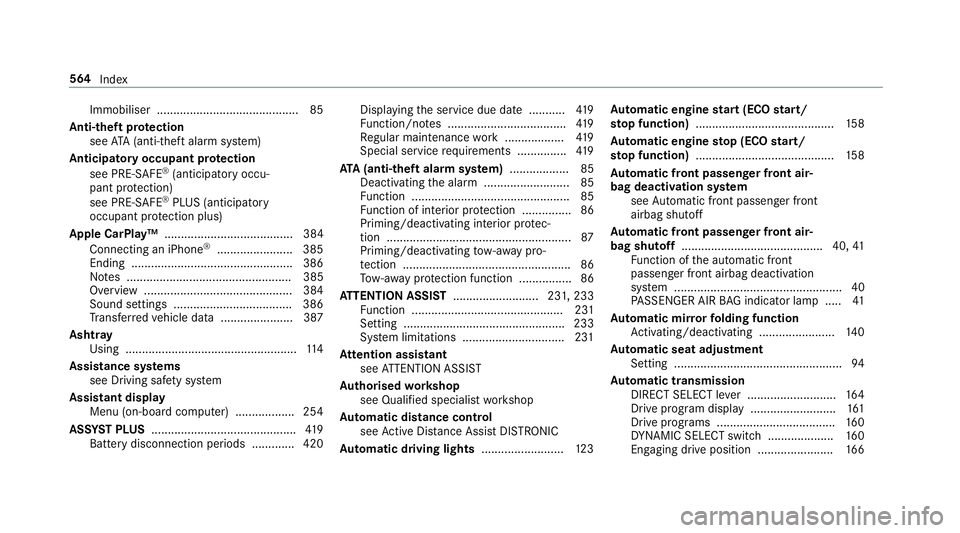
Au tomatic transmission
DIRECT SELECT le ver ........................... 16 4
Drive prog ram display ......................... .161
Drive prog rams ................................... .160
DY NA MIC SELECT switch .................... 16 0
Engaging drive position ....................... 16 6564
Index