MERCEDES-BENZ B-Class ELECTRIC 2015 W246 Owner's Manual
Manufacturer: MERCEDES-BENZ, Model Year: 2015, Model line: B-Class ELECTRIC, Model: MERCEDES-BENZ B-Class ELECTRIC 2015 W246Pages: 338, PDF Size: 6.61 MB
Page 181 of 338
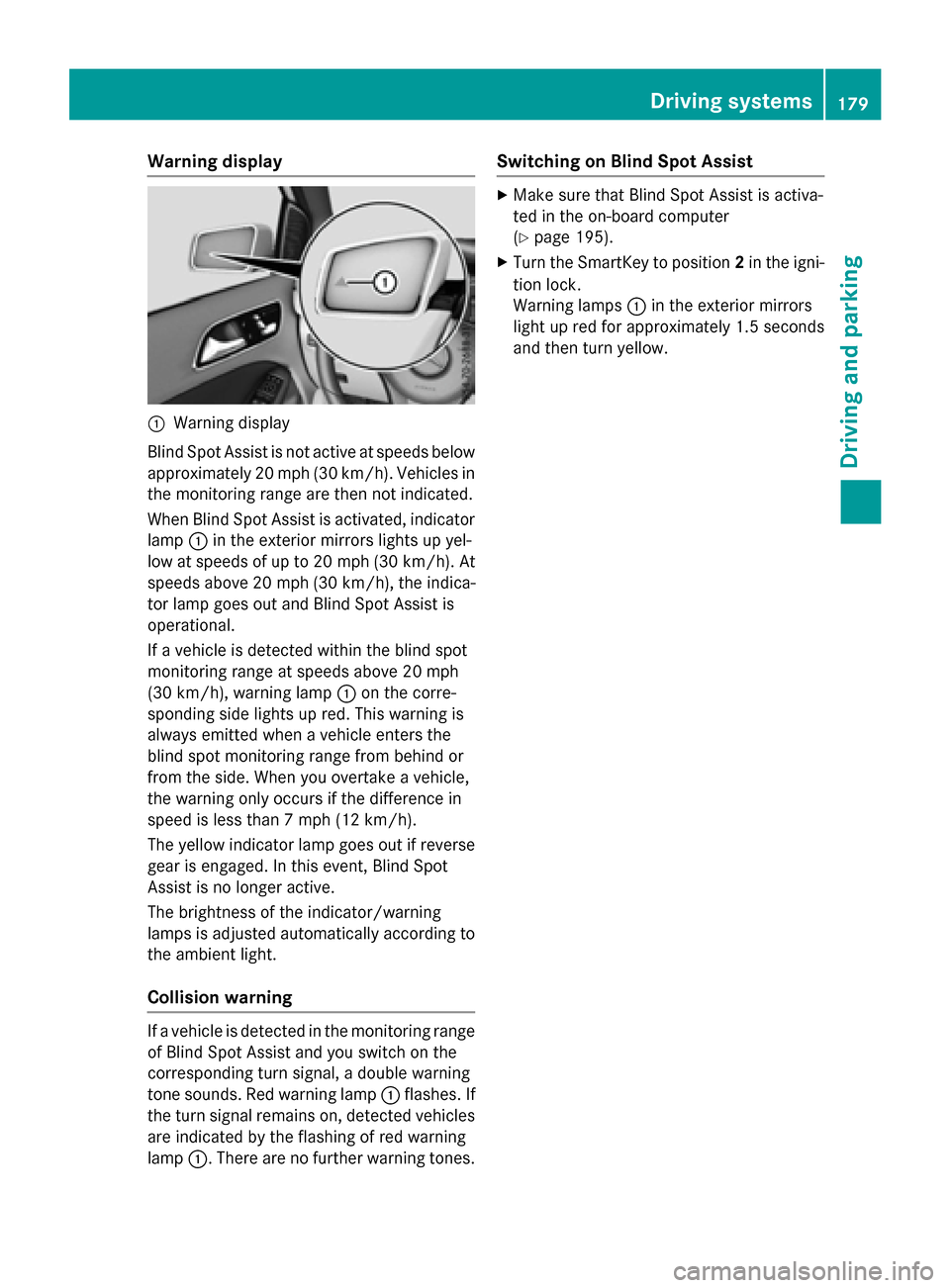
Warning display
:
Warning display
Blind Spot Assist is not active at speeds below approximately 20 mph (30 km/h). Vehicles in the monitoring range are then not indicated.
When Blind Spot Assist is activated, indicator
lamp :in the exterior mirrors lights up yel-
low at speeds of up to 20 mph (30 km/h). At speeds above 20 mph (30 km/h), the indica-
tor lamp goes out and Blind Spot Assist is
operational.
If a vehicle is detected within the blind spot
monitoring range at speeds above 20 mph
(30 km/h), warning lamp :on the corre-
sponding side lights up red. This warning is
always emitted when a vehicle enters the
blind spot monitoring range from behind or
from the side. When you overtake a vehicle,
the warning only occurs if the difference in
speed is less than 7 mph (12 km/h).
The yellow indicator lamp goes out if reverse gear is engaged. In this event, Blind Spot
Assist is no longer active.
The brightness of the indicator/warning
lamps is adjusted automatically according to
the ambient light.
Collision warning If a vehicle is detected in the monitoring range
of Blind Spot Assist and you switch on the
corresponding turn signal, a double warning
tone sounds. Red warning lamp :flashes. If
the turn signal remains on, detected vehicles
are indicated by the flashing of red warning
lamp :. There are no further warning tones. Switching on Blind Spot Assist X
Make sure that Blind Spot Assist is activa-
ted in the on-board computer
(Y page 195).
X Turn the SmartKey to position 2in the igni-
tion lock.
Warning lamps :in the exterior mirrors
light up red for approximately 1.5 seconds
and then turn yellow. Driving systems
179Driving and parking Z
Page 182 of 338

180
Page 183 of 338
Useful information
............................182
Important safety notes .....................182
Displays and operation .....................182
Menus and submenus ......................186
Display messages ............................. 200
Warning and indicator lamps in the instrument cluster ............................227 181On-board computer and displays
Page 184 of 338
Useful information
i This Operator's Manual describes all
models and all standard and optional equip- ment of your vehicle available at the time of
publication of the Operator's Manual.
Country-specific differences are possible.
Please note that your vehicle may not be
equipped with all features described. This
also applies to safety-related systems and
functions.
i Read the information on qualified special-
ist workshops (Y page 25). Important safety notes
G
WARNING
If you operate information systems and com-
munication equipment integrated in the vehi- cle while driving, you will be distracted from
traffic conditions. You could also lose control of the vehicle. There is a risk of an accident.
Only operate the equipment when the traffic
situation permits. If you are not sure that this
is possible, park the vehicle paying attention
to traffic conditions and operate the equip-
ment when the vehicle is stationary.
You must observe the legal requirements for
the country in which you are currently driving when operating the on-board computer. G
WARNING
If the instrument cluster has failed or mal-
functioned, you may not recognize function
restrictions in systems relevant to safety. The operating safety of your vehicle may be
impaired. There is a risk of an accident.
Drive on carefully. Have the vehicle checked
at a qualified specialist workshop immedi-
ately.
The on-board computer only shows messages
or warnings from certain systems in the mul- tifunction display. You should therefore make sure your vehicle is operating safely at all
times.
If the operating safety of your vehicle is
impaired, pull over as soon as it is safe to do
so. Contact a qualified specialist workshop.
For an overview, see the instrument panel
illustration (Y page 31). Displays and operation
Instrument cluster lighting
The light sensor in the instrument cluster
automatically controls the brightness of the
multifunction display. In daylight, the displays
in the instrument cluster are not illuminated.
The lighting in the instrument cluster, in the
displays and the controls in the vehicle inte-
rior can be adjusted using the brightness con- trol knob.
The brightness control knob is located on the
bottom left of the instrument cluster
(Y page 31).
X Turn the brightness control knob clockwise
or counter-clockwise.
If the light switch is set to Ã,Tor
L, the brightness is dependent upon
the brightness of the ambient light. READY indicator
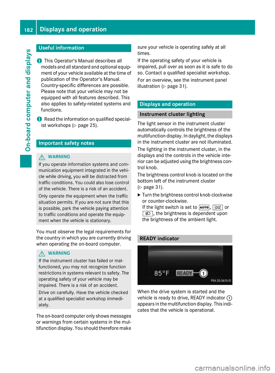
When the drive system is started and the
vehicle is ready to drive, READY indicator
:
appears in the multifunction display. This indi- cates that the vehicle is operational. 182
Displays and operationOn-board computer and displays
Page 185 of 338
Outside temperature display
You should pay special attention to road con-
ditions when temperatures are around freez-
ing point.
Bear in mind that the outside temperature
display indicates the temperature measured
and does not record the road temperature.
The outside temperature display is in the mul- tifunction display (Y page 186).
Changes in the outside temperature are dis-
played after a short delay. E-CELL display
G
WARNING
There is a risk of an accident if you accelerate or overtake when the power output of the
drive system is reduced.
You should therefore adapt your driving style
and drive particularly carefully. Charge the
high-voltage battery at a charge station imme- diately. X
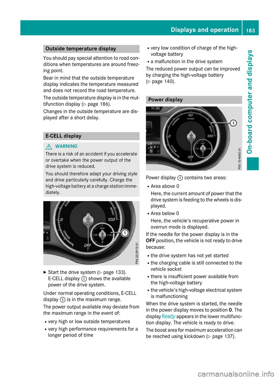
Start the drive system (Y page 133).
E-CELL display :shows the available
power of the drive system.
Under normal operating conditions, E-CELL
display :is in the maximum range.
The power output available may deviate from
the maximum range in the event of:
R very high or low outside temperatures
R very high performance requirements for a
longer period of time R
very low condition of charge of the high-
voltage battery
R a malfunction in the drive system
The reduced power output can be improved
by charging the high-voltage battery
(Y page 140). Power display
Power display
:contains two areas:
R Area above 0
Here, the current amount of power that the
drive system is feeding to the wheels is dis-
played.
R Area below 0
Here, the vehicle's recuperative power in
overrun mode is displayed.
If the needle for the power display is in the
OFF position, the vehicle is not ready to drive
because:
R the drive system has not yet started
R the charging cable is still connected to the
vehicle socket
R there is insufficient power available from
the high-voltage battery
R the vehicle's high-voltage electrical system
is malfunctioning
When the drive system is started, the needle
in the power display moves to position 0. The
display Ready
Ready appears in the lower multifunc-
tion display. The vehicle is ready to drive.
The boost area for maximum acceleration can
be reached using kickdown (Y page 137). Displays and operation
183On-board computer and displays Z
Page 186 of 338
The braking performance of the electric
motor using recuperative braking is, in some
operating modes, either reduced or not effec-
tive:
R when the condition of charge of the high-
voltage battery increases
R if the high-voltage battery is not yet at a
normal operating temperature
R when driving close to the maximum speed
R when the vehicle is almost stationary
R in transmission position N
R during and after ESP stability control
If necessary, counteract the reduced regen-
erative braking effect by applying the brake
yourself. Charge level display
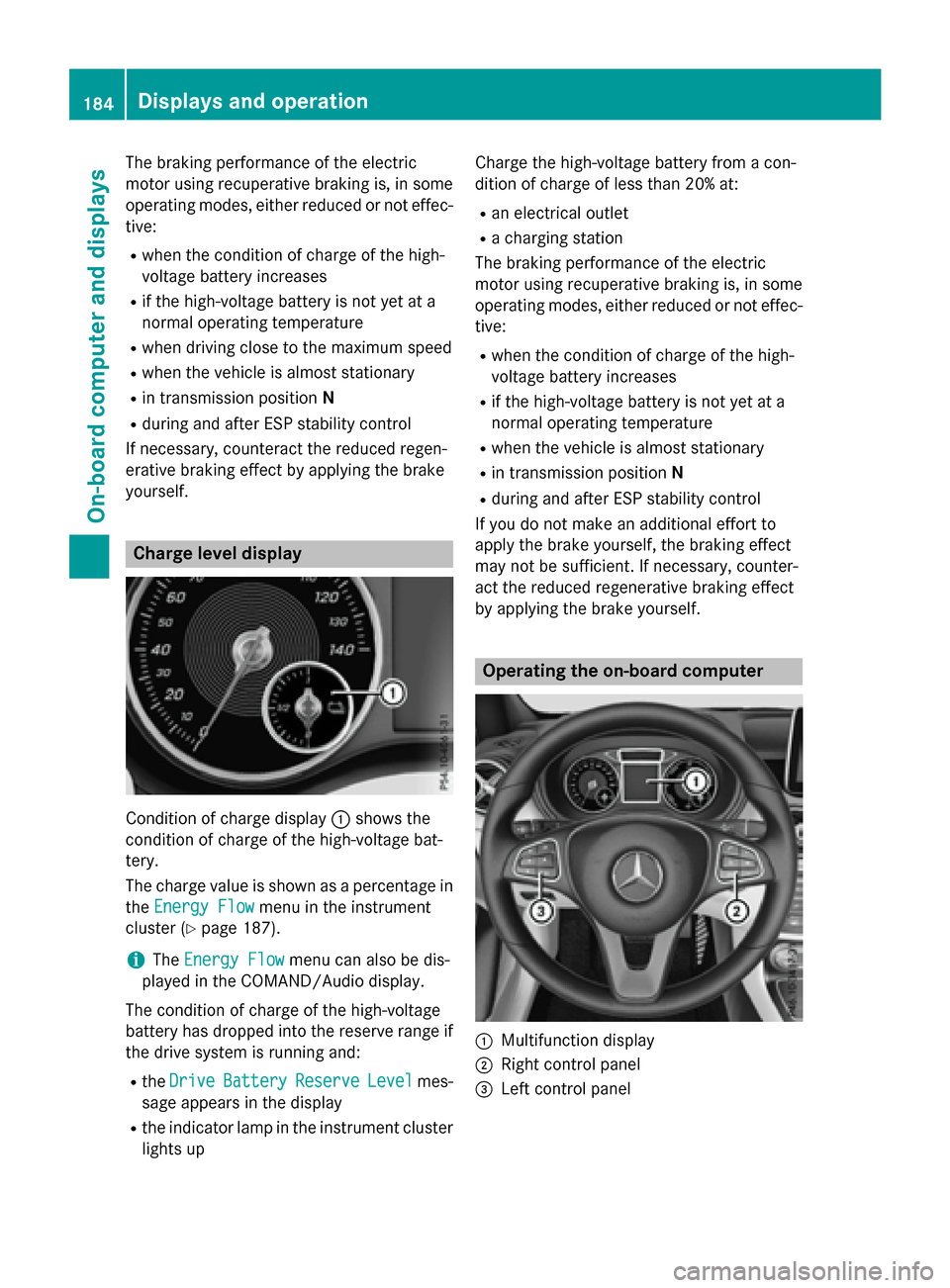
Condition of charge display
:shows the
condition of charge of the high-voltage bat-
tery.
The charge value is shown as a percentage in
the Energy Flow Energy Flow menu in the instrument
cluster (Y page 187).
i The
Energy Flow
Energy Flow menu can also be dis-
played in the COMAND/Audio display.
The condition of charge of the high-voltage
battery has dropped into the reserve range if
the drive system is running and:
R the Drive Drive Battery
Battery Reserve
ReserveLevel
Levelmes-
sage appears in the display
R the indicator lamp in the instrument cluster
lights up Charge the high-voltage battery from a con-
dition of charge of less than 20% at:
R an electrical outlet
R a charging station
The braking performance of the electric
motor using recuperative braking is, in some
operating modes, either reduced or not effec-
tive:
R when the condition of charge of the high-
voltage battery increases
R if the high-voltage battery is not yet at a
normal operating temperature
R when the vehicle is almost stationary
R in transmission position N
R during and after ESP stability control
If you do not make an additional effort to
apply the brake yourself, the braking effect
may not be sufficient. If necessary, counter-
act the reduced regenerative braking effect
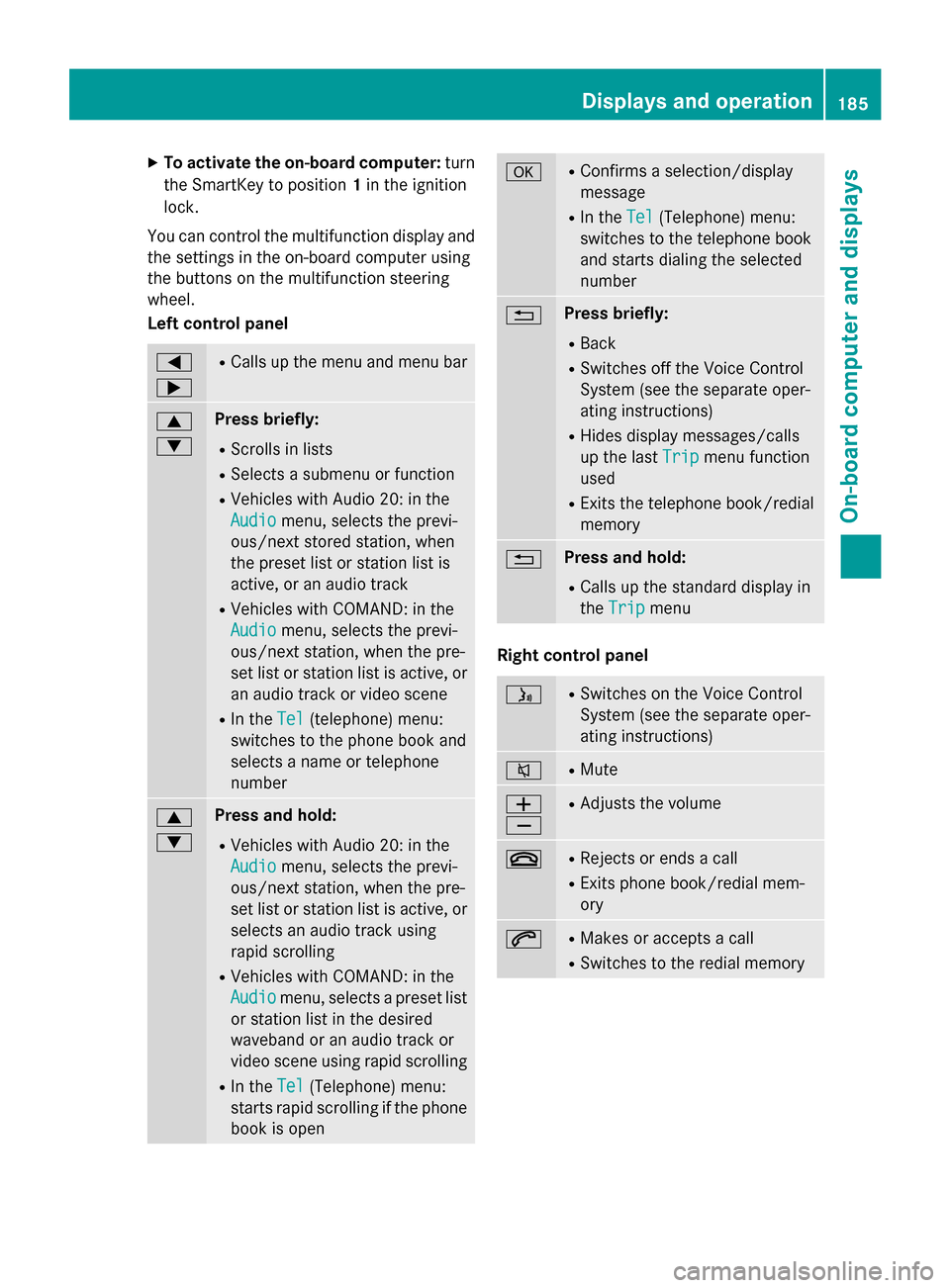
by applying the brake yourself. Operating the on-board computer
:
Multifunction display
; Right control panel
= Left control panel 184
Displays and operationOn-board computer and displays
Page 187 of 338
X
To activate the on-board computer: turn
the SmartKey to position 1in the ignition
lock.
You can control the multifunction display and
the settings in the on-board computer using
the buttons on the multifunction steering
wheel.
Left control panel =
; R
Calls up the menu and menu bar 9
: Press briefly:
R Scrolls in lists
R Selects a submenu or function
R Vehicles with Audio 20: in the
Audio Audio menu, selects the previ-
ous/next stored station, when
the preset list or station list is
active, or an audio track
R Vehicles with COMAND: in the
Audio Audio menu, selects the previ-
ous/next station, when the pre-
set list or station list is active, or
an audio track or video scene
R In the Tel Tel(telephone) menu:
switches to the phone book and
selects a name or telephone
number 9
: Press and hold:
R Vehicles with Audio 20: in the
Audio Audio menu, selects the previ-
ous/next station, when the pre-
set list or station list is active, or
selects an audio track using
rapid scrolling
R Vehicles with COMAND: in the
Audio Audio menu, selects a preset list
or station list in the desired
waveband or an audio track or
video scene using rapid scrolling
R In the Tel Tel(Telephone) menu:
starts rapid scrolling if the phone book is open a R
Confirms a selection/display
message
R In the Tel Tel(Telephone) menu:
switches to the telephone book
and starts dialing the selected
number % Press briefly:
R Back
R Switches off the Voice Control
System (see the separate oper-
ating instructions)
R Hides display messages/calls
up the last Trip Tripmenu function
used
R Exits the telephone book/redial
memory % Press and hold:
R Calls up the standard display in
the Trip Trip menu Right control panel
ó R
Switches on the Voice Control
System (see the separate oper-
ating instructions) 8 R
Mute W
X R
Adjusts the volume ~ R
Rejects or ends a call
R Exits phone book/redial mem-
ory 6 R
Makes or accepts a call
R Switches to the redial memory Displays and operation
185On-board computer and displays Z
Page 188 of 338
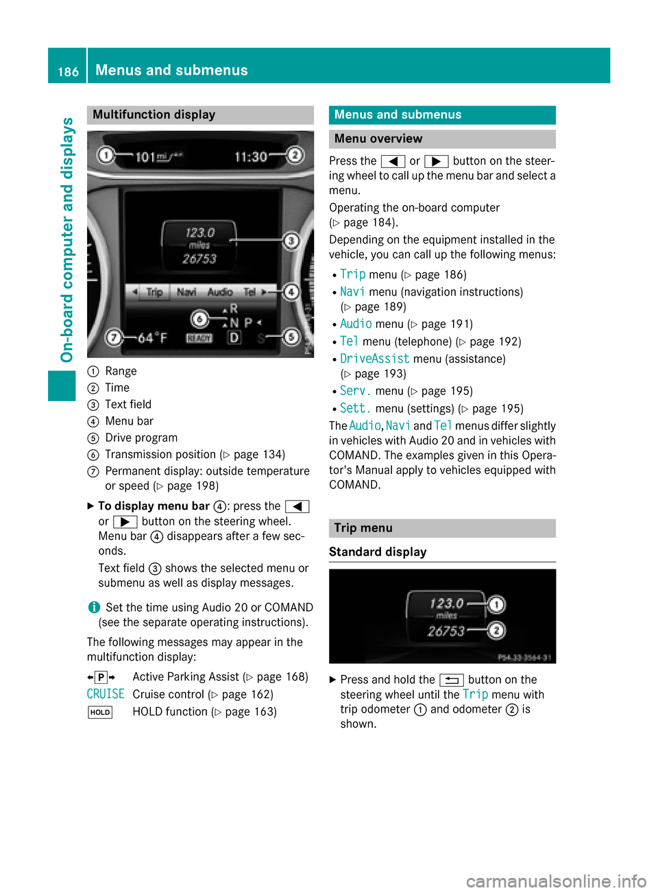
Multifunction display
:
Range
; Time
= Text field
? Menu bar
A Drive program
B Transmission position (Y page 134)
C Permanent display: outside temperature
or speed (Y page 198)
X To display menu bar ?: press the=
or ; button on the steering wheel.
Menu bar ?disappears after a few sec-
onds.
Text field =shows the selected menu or
submenu as well as display messages.
i Set the time using Audio 20 or COMAND
(see the separate operating instructions).
The following messages may appear in the
multifunction display:
XjY Active Parking Assist (Y page 168)
CRUISE
CRUISE Cruise control (Y
page 162)
ë HOLD function (Y page 163) Menus and submenus
Menu overview
Press the =or; button on the steer-
ing wheel to call up the menu bar and select a
menu.
Operating the on-board computer
(Y page 184).
Depending on the equipment installed in the
vehicle, you can call up the following menus:
R Trip Trip menu (Y page 186)
R Navi
Navi menu (navigation instructions)
(Y page 189)
R Audio
Audio menu (Y page 191)
R Tel
Tel menu (telephone) (Y page 192)
R DriveAssist
DriveAssist menu (assistance)
(Y page 193)
R Serv.
Serv. menu (Y page 195)
R Sett.
Sett. menu (settings) (Y page 195)
The Audio
Audio, Navi
NaviandTel
Tel menus differ slightly
in vehicles with Audio 20 and in vehicles with
COMAND. The examples given in this Opera-
tor's Manual apply to vehicles equipped with
COMAND. Trip menu
Standard display X
Press and hold the %button on the
steering wheel until the Trip
Trip menu with
trip odometer :and odometer ;is
shown. 186
Menus and submenusOn-board computer and displays
Page 189 of 338
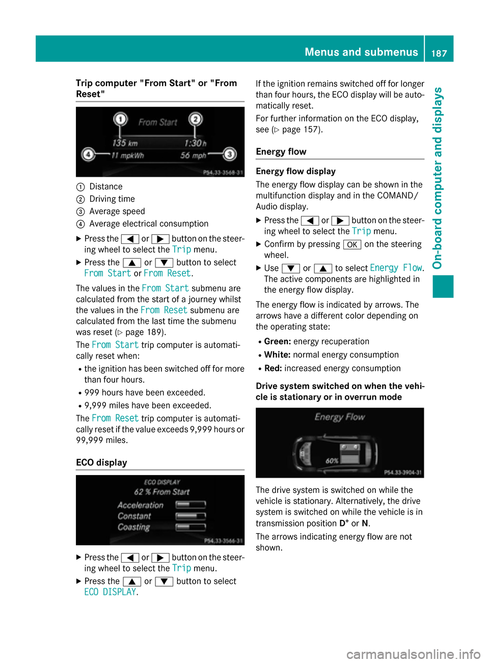
Trip computer "From Start" or "From
Reset" :
Distance
; Driving time
= Average speed
? Average electrical consumption
X Press the =or; button on the steer-
ing wheel to select the Trip
Tripmenu.
X Press the 9or: button to select
From Start
From Start orFrom Reset
From Reset.
The values in the From Start
From Startsubmenu are
calculated from the start of a journey whilst
the values in the From Reset From Resetsubmenu are
calculated from the last time the submenu
was reset (Y page 189).
The From Start From Start trip computer is automati-
cally reset when:
R the ignition has been switched off for more
than four hours.
R 999 hours have been exceeded.
R 9,999 miles have been exceeded.
The From Reset
From Reset trip computer is automati-
cally reset if the value exceeds 9,999 hours or 99,999 miles.
ECO display X
Press the =or; button on the steer-
ing wheel to select the Trip
Tripmenu.
X Press the 9or: button to select
ECO DISPLAY
ECO DISPLAY. If the ignition remains switched off for longer
than four hours, the ECO display will be auto-
matically reset.
For further information on the ECO display,
see (Y page 157).
Energy flow Energy flow display
The energy flow display can be shown in the
multifunction display and in the COMAND/
Audio display.
X Press the =or; button on the steer-
ing wheel to select the Trip Tripmenu.
X Confirm by pressing aon the steering
wheel.
X Use : or9 to select Energy Flow
Energy Flow .
The active components are highlighted in
the energy flow display.
The energy flow is indicated by arrows. The
arrows have a different color depending on
the operating state: R Green: energy recuperation
R White: normal energy consumption
R Red: increased energy consumption
Drive system switched on when the vehi-
cle is stationary or in overrun mode The drive system is switched on while the
vehicle is stationary. Alternatively, the drive
system is switched on while the vehicle is in
transmission position D+
or N.
The arrows indicating energy flow are not
shown. Menus and submenus
187On-board computer and displays Z
Page 190 of 338
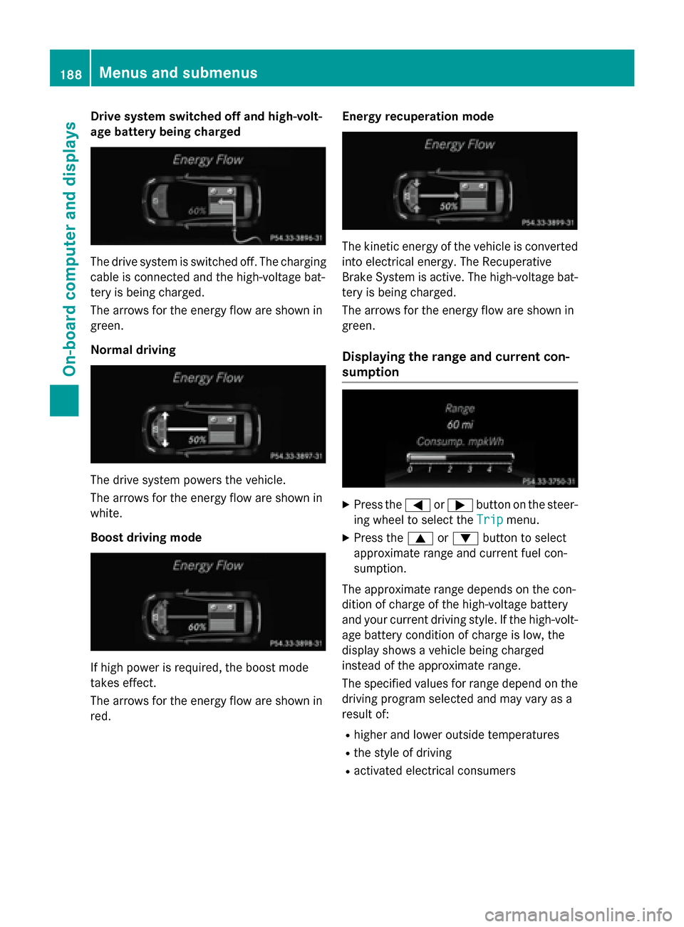
Drive system switched off and high-volt-
age battery being charged The drive system is switched off. The charging
cable is connected and the high-voltage bat-
tery is being charged.
The arrows for the energy flow are shown in
green.
Normal driving The drive system powers the vehicle.
The arrows for the energy flow are shown in
white.
Boost driving mode If high power is required, the boost mode
takes effect.
The arrows for the energy flow are shown in
red. Energy recuperation mode The kinetic energy of the vehicle is converted
into electrical energy. The Recuperative
Brake System is active. The high-voltage bat-
tery is being charged.
The arrows for the energy flow are shown in
green.
Displaying the range and current con-
sumption X
Press the =or; button on the steer-
ing wheel to select the Trip Tripmenu.
X Press the 9or: button to select
approximate range and current fuel con-
sumption.
The approximate range depends on the con-
dition of charge of the high-voltage battery
and your current driving style. If the high-volt- age battery condition of charge is low, the
display shows a vehicle being charged
instead of the approximate range.
The specified values for range depend on the
driving program selected and may vary as a
result of:
R higher and lower outside temperatures
R the style of driving
R activated electrical consumers 188
Menus and sub
menusOn-board computer and displays