tow MERCEDES-BENZ B-Class ELECTRIC 2015 W246 Owner's Manual
[x] Cancel search | Manufacturer: MERCEDES-BENZ, Model Year: 2015, Model line: B-Class ELECTRIC, Model: MERCEDES-BENZ B-Class ELECTRIC 2015 W246Pages: 338, PDF Size: 6.61 MB
Page 5 of 338
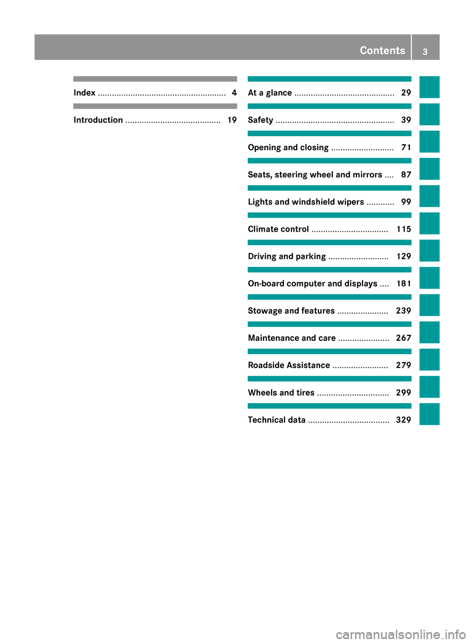
Index
....................................................... 4Introduction
......................................... 19 At a glance
........................................... 29 Safety
................................................... 39 Opening and closing
...........................71 Seats, steering wheel and mirrors
....87 Lights and windshield wipers
............99 Climate control
................................. 115 Driving and parking
..........................129 On-board computer and displays
....181 Stowage and features
......................239 Maintenance and care
......................267 Roadside Assistance
........................279 Wheels and tires
............................... 299 Technical data
................................... 329 Contents
3
Page 7 of 338
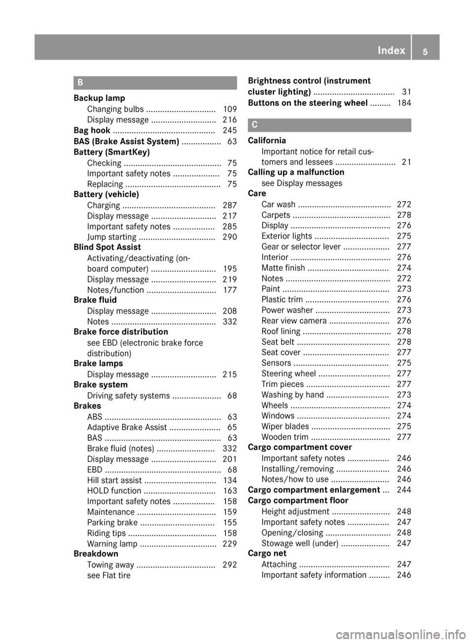
B
Backup lamp Changing bulb s.............................. 109
Display message ............................ 216
Bag hook ............................................ 245
BAS (Brake Assist System) ................. 63
Battery (SmartKey)
Checking .......................................... 75
Important safety notes .................... 75
Replacing ......................................... 75
Battery (vehicle)
Charging ........................................ 287
Display message ............................ 217
Important safety notes .................. 285
Jump starting ................................. 290
Blind Spot Assist
Activating/deactivating (on-
board computer) ............................ 195
Display message ............................ 219
Notes/function .............................. 177
Brake fluid
Display message ............................ 208
Notes ............................................. 332
Brake force distribution
see EBD (electronic brake force
distribution)
Brake lamps
Display message ............................ 215
Brake system
Driving safety systems ..................... 68
Brakes
ABS .................................................. 63
Adaptive Brake Assist ...................... 65
BAS .................................................. 63
Brake fluid (notes) ......................... 332
Display message ............................ 201
EBD .................................................. 68
Hill start assist ............................... 134
HOLD function ............................... 163
Important safety notes .................. 158
Maintenance .................................. 159
Parking brake ................................ 155
Riding tips ...................................... 158
Warning lamp ................................. 229
Breakdown
Towing away .................................. 292
see Flat tire Brightness control (instrument
cluster lighting)
................................... 31
Buttons on the steering wheel ......... 184 C
California Important notice for retail cus-
tomers and lessees .......................... 21
Calling up a malfunction
see Display messages
Care
Car wash ........................................ 272
Carpets .......................................... 278
Display ........................................... 276
Exterior lights ................................ 275
Gear or selector lever .................... 277
Interior ........................................... 276
Matte finish ................................... 274
Note s............................................. 272
Paint .............................................. 273
Plastic trim .................................... 276
Power washer ................................ 273
Rear view camera .......................... 276
Roof lining ...................................... 278
Seat belt ........................................ 278
Seat cove r..................................... 277
Sensors ......................................... 275
Steering wheel ............................... 277
Trim pieces .................................... 277
Washing by hand ........................... 273
Wheels ........................................... 274
Windows ........................................ 274
Wiper blades .................................. 275
Wooden trim .................................. 277
Cargo compartment cover
Important safety notes .................. 246
Installing/removing ....................... 246
Notes/how to use ......................... 246
Cargo compartment enlargement ... 244
Cargo compartment floor
Height adjustment ......................... 248
Important safety notes .................. 247
Opening/closing ............................ 248
Stowage well (under )..................... 247
Cargo net
Attaching ....................................... 247
Important safety information ......... 246 Index
5
Page 17 of 338
Problem (malfunction) ..................... 77
SmartKey positions (ignition lock) .. 131
Snow chains ...................................... 303
Sockets
Center console .............................. 252
General notes ................................ 252
Luggage compartment ...................2 53
Rear compartment ......................... 253
Special seat belt retractor .................. 57
Specialist workshop ............................ 25
Speed, controlling
see Cruise control
Speedometer
Activating/deactivating the addi-
tional speedometer ........................ 198
Digital ............................................ 189
In the Instrument cluster ................. 31
Selecting the unit of measure-
ment .............................................. 197
Standing lamps
Changing bulbs .............................. 108
Display message ............................ 216
Switching on/off ........................... 101
Start/Stop button
Removing ....................................... 132
Starting the drive system .............. .133
Starting (vehicle) ............................... 132
STEER CONTROL .................................. 68
Steering (display message) .............. 225
Steering assistant STEER CON-
TROL
see STEER CONTROL
Steering wheel
Adjusting (manually) ........................ 93
Button overview ............................... 33
Buttons (on-board computer) ......... 184
Cleaning ......................................... 277
Important safety notes .................... 93
Paddle shifters ............................... 138
Steering wheel paddle shifters ........ 138
Stowage compartments
Armrest (front) ............................... 241
Armrest (under) ............................. 242
Center console .............................. 241
Center console (rear) ..................... 242
Cup holders ................................... 249
Eyeglasses compartment ............... 241 Glove box ....................................... 241
Important safety information ......... 240
Map pockets .................................. 243
Stowage net ................................... 243
Under driver's seat/front-
passenger sea
t.............................. 242
Stowage net ....................................... 243
Summer tires ..................................... 302
Sun visor ............................................ 251
Switching air-recirculation mode
on/off ................................................. 123 T
Tail lamps see Lights
Tailgate
Display message ............................ 224
Emergency unlocking ....................... 82
Important safety notes .................... 81
Opening dimensions ...................... 334
Opening/closing (from outside) ....... 82
Technical data
Capacities ...................................... 331
Information .................................... 330
Tires/wheels ................................. 325
Vehicle data ................................... 334
Telephone
Accepting a call (multifunction
steering wheel) .............................. 192
Display message ............................ 225
Introduction ................................... 192
Menu (on-board computer) ............ 192
Number from the phone book ........ 192
Redialing ........................................ 193
Rejecting/ending a call ................. 192
Temperature
Outside temperature ...................... 183
Setting (climate control )................ 120
Through-loading feature ................... 243
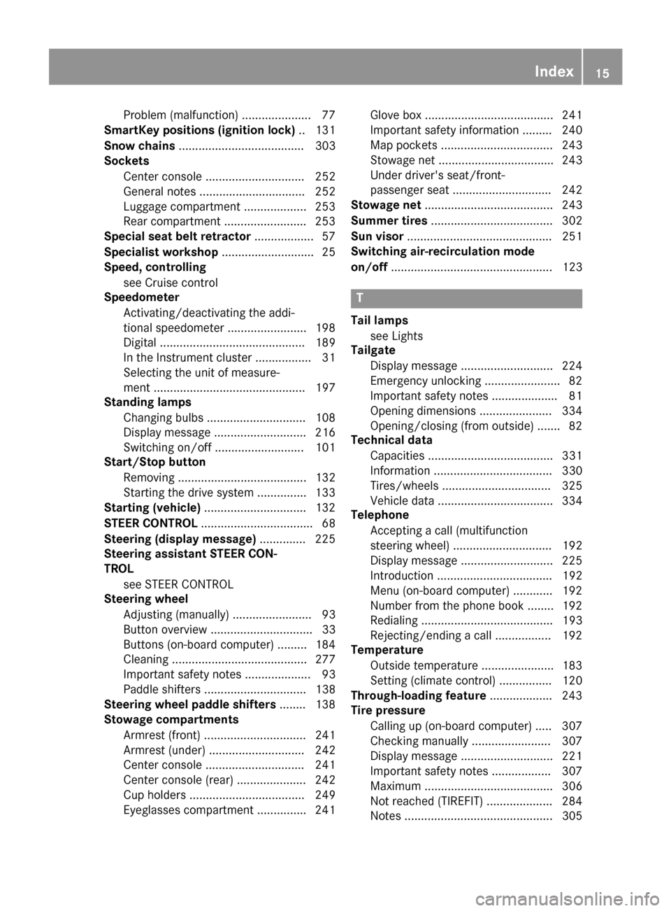
Tire pressure
Calling up (on-board computer) ..... 307
Checking manually ........................ 307
Display message ............................ 221
Important safety notes .................. 307
Maximum ....................................... 306
Not reached (TIREFIT) .................... 284
Note s............................................. 305 Index
15
Page 18 of 338
Reached (TIREFIT) .......................... 284
Recommended ..............................
.303
Tire pressure monitor
Checking the tire pressure elec-
tronically ........................................ 309
Function/notes ............................ .307
General notes ................................ 307
Important safety notes .................. 307
Radio type approval for the tire
pressure monitor ........................... 310
Restarting ...................................... 309
Warning lamp ................................. 238
Warning message .......................... 309
TIREFIT kit .......................................... 282
Tires
Aspect ratio (definition) ................. 320
Average weight of the vehicle
occupants (definition) .................... 319
Bar (definition) ............................... 318
Changing a wheel .......................... 321
Characteristics .............................. 318
Checking ........................................ 301
Curb weight (definition) ................. 320
Definition of terms ......................... 318
Direction of rotatio n...................... 321
Display message ............................ 221
Distribution of the vehicle occu-
pants (definition) ............................ 321
DOT (Department of Transporta-
tion) (definition) ............................. 319
DOT, Tire Identification Number
(TIN) ............................................... 318
GAWR (Gross Axle Weight Rating)
(definition) ..................................... 319
General notes ................................ 325
GVW (Gross Vehicle Weight) (def-
inition) ........................................... 319
GVWR (Gross Vehicle Weight Rat-
ing) (definition) .............................. 319
Important safety notes .................. 300
Increased vehicle weight due to
optional equipment (definition) ...... 319
Information on driving .................... 300
Kilopascal (kPa) (definition) ........... 319
Labeling (overview) ........................ 315
Load bearing index (definition) ...... 320
Load index ..................................... 317
Load index (definition) ................... 319 M+S tire
s....................................... 302
Maximum load on a tire (defini-
tion) ............................................... 320
Maximum loaded vehicle weight
(definition) ..................................... 319
Maximum permissible tire pres-
sure (definition) ............................. 320
Maximum tire load ......................... 317
Maximum tire load (definition) ....... 320
MOExtended tire s.......................... 302
Optional equipment weight (defi-
nition) ............................................ 320
PSI (pounds per square inch) (def-
inition) ........................................... 320
Replacing ....................................... 321
Service life ..................................... 302
Sidewall (definition) ....................... 320
Speed rating (definition) ................ 319
Storing ........................................... 321
Structure and characteristics
(definition) ..................................... 318
Summer tire s................................. 302
Temperature .................................. 314
TIN (Tire Identification Number)
(definition) ..................................... 320
Tire bead (definition) ...................... 320
Tire pressure (definition) ................ 320
Tire pressures (recommended) ...... 319
Tire size (data) ............................... 325
Tire size designation, load-bearing capacity, speed rating .................... 315
Tire tread ....................................... 301
Tire tread (definition) ..................... 320
Total load limit (definition) ............. 321
Traction ......................................... 314
Traction (definition) ....................... 320
Tread wear ..................................... 314
Uniform Tire Quality Grading
Standards ...................................... 313
Uniform Tire Quality Grading
Standards (definition) .................... 319
Wear indicator (definition) ............. 320
Wheel and tire combination ........... 327
Wheel rim (definition) .................... 319
see Flat tire
Top Tether ............................................ 59
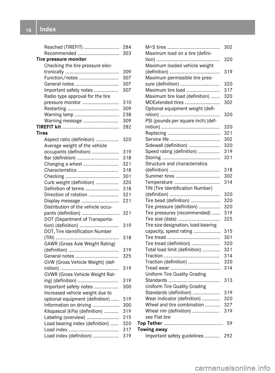
Towing away
Important safety guidelines ........... 292 16
Index
Page 19 of 338
Installing the towing eye ................ 294
Removing the towing eye ............... 294
Transporting the vehicle ................ 295
With both axles on the ground ....... 294
With front axle raised .....................2 95
With the rear axle raised ................ 295
Towing eye ......................................... 280
Trailer hitch ......................................... 24
Trailer tow hitch .................................. 24
Transmission
DIRECT SELECT lever ..................... 134
Drive program ................................ 137
Driving tips ................................... .137
Engaging the drive position ............ 136
Engaging the park position ............ 135
Holding the vehicle stationary on
uphill gradients .............................. 137
Kickdown ....................................... 137
Overview ........................................ 134
Program selector button ................ 137
Shifting to neutra l.......................... 135
Transmission position display ......... 134
Transmission position display
(DIRECT SELECT lever) ...................... 134
Transmission positions .................... 136
Transporting the vehicle .................. 295
Trim pieces (cleaning instruc-
tions) .................................................. 277
Trip computer (on-board com-
puter) .................................................. 187
Trip odometer
Calling up ....................................... 186
Resetting (on-board computer) ...... 189
Trunk load (maximum) ...................... 334
Turn signals
Changing bulbs (front) ................... 108
Display message ............................ 214
Switching on/of f........................... 102
Type identification plate
see Vehicle identification plate U
Unlocking Emergency unlocking ....................... 80
From inside the vehicle (central
unlocking button) ............................. 80 V
Vanity mirror (in the sun visor) ........ 251
Vehicle
Correct use ...................................... 25
Data acquisition ............................... 26
Display message ............................ 223
Equipment ....................................... 20
Individual settings .......................... 195
Limited Warranty ............................. 26
Loading .......................................... 310
Locking (in an emergency) ............... 81
Locking (SmartKey) .......................... 72
Lowering ........................................ 325
Maintenance .................................... 21
Parking for a long period ................ 156
Raising ........................................... 322
Reporting problems ......................... 25
Securing from rolling away ............ 322
Starting .......................................... 132
Transporting .................................. 295
Unlocking (in an emergency) ........... 80
Unlocking (SmartKey) ...................... 72
Vehicle data ................................... 334
Vehicle data
Roof load (maximum) ..................... 334
Trunk load (maximum) ................... 334
Vehicle dimensions ........................... 334
Vehicle emergency locking ................ 81
Vehicle Homepage
Data protection .............................. 152
Functions ....................................... 153
General information ....................... 152
Internet connection ....................... 153
Vehicle identification number
see VIN
Vehicle identification plate .............. 330
Vehicle tool kit .................................. 280
Ventilation
Setting the vents ........................... 126
Video
Operating the DVD ......................... 191
VIN ...................................................... 330 W
Warning and indicator lamps ABS ................................................ 230 Index
17
Page 25 of 338
Danger of electric shock
G
DANGER
The vehicle's high voltage electrical system is under high voltage. If you modify components
in the vehicle's high-voltage electrical system or touch damaged components, you may be
electrocuted. The components in the vehi-
cle's high-voltage electrical system may be
damaged in an accident, although the damage
is not visible. There is a risk of fatal injury.
Following an accident, do not touch any high- voltage components and never modify the
vehicle's high-voltage electrical system. Have
the vehicle towed away after an accident and the vehicle's high-voltage electrical system
checked by a qualified specialist workshop. All of the vehicle's high-voltage electrical sys-
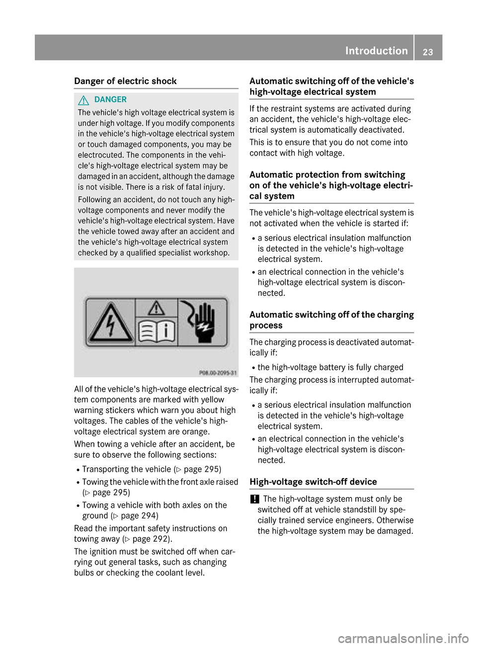
tem components are marked with yellow
warning stickers which warn you about high
voltages. The cables of the vehicle's high-
voltage electrical system are orange.
When towing a vehicle after an accident, be
sure to observe the following sections:
R Transporting the vehicle (Y page 295)
R Towing the vehicle with the front axle raised
(Y page 295)
R Towing a vehicle with both axles on the
ground (Y page 294)
Read the important safety instructions on
towing away (Y page 292).
The ignition must be switched off when car-
rying out general tasks, such as changing
bulbs or checking the coolant level. Automatic switching off of the vehicle's
high-voltage electrical system If the restraint systems are activated during
an accident, the vehicle's high-voltage elec-
trical system is automatically deactivated.
This is to ensure that you do not come into
contact with high voltage.
Automatic protection from switching
on of the vehicle's high-voltage electri-
cal system The vehicle's high-voltage electrical system is
not activated when the vehicle is started if:
R a serious electrical insulation malfunction
is detected in the vehicle's high-voltage
electrical system.
R an electrical connection in the vehicle's
high-voltage electrical system is discon-
nected.
Automatic switching off of the charging process The charging process is deactivated automat-
ically if:
R the high-voltage battery is fully charged
The charging process is interrupted automat- ically if:
R a serious electrical insulation malfunction
is detected in the vehicle's high-voltage
electrical system.
R an electrical connection in the vehicle's
high-voltage electrical system is discon-
nected.
High-voltage switch-off device !
The high-voltage system must only be
switched off at vehicle standstill by spe-
cially trained service engineers. Otherwise
the high-voltage system may be damaged. Int
roduction
23 Z
Page 26 of 338
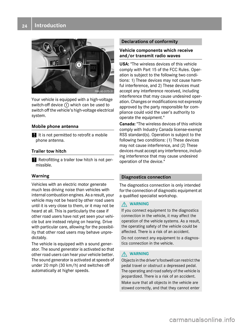
Your vehicle is equipped with a high-voltage
switch-off device :which can be used to
switch off the vehicle's high-voltage electrical
system.
Mobile phone antenna !
It is not permitted to retrofit a mobile
phone antenna.
Trailer tow hitch !
Retrofitting a trailer tow hitch is not per-
missible.
Warning Vehicles with an electric motor generate
much less driving noise than vehicles with
internal combustion engines. As a result, your
vehicle may not be heard by other road users
until it is very close to them, or it may not be heard at all. This is particularly the case if
other road users have not yet seen your vehi- cle but are instead relying on hearing. Drive
with particular care, allowing for the possibil-
ity that other road users may behave unpre-
dictably.
The vehicle is equipped with a sound gener-
ator. The sound generator is activated so that
other road users can hear your vehicle better. The sound generator is activated at speeds of under 20 mph (30 km/h) and switches off
automatically at higher speeds. Declarations of conformity
Vehicle components which receive
and/or transmit radio waves USA:
"The wireless devices of this vehicle
comply with Part 15 of the FCC Rules. Oper-
ation is subject to the following two condi-
tions: 1) These devices may not cause harm-
ful interference, and 2) These devices must
accept any interference received, including
interference that may cause undesired oper-
ation. Changes or modifications not expressly approved by the party responsible for com-
pliance could void the user’s authority to
operate the equipment."
Canada: "The wireless devices of this vehicle
comply with Industry Canada license-exempt RSS standard(s). Operation is subject to the
following two conditions: (1) These devices
may not cause interference, and (2) These
devices must accept any interference, includ-
ing interference that may cause undesired
operation of the device." Diagnostics connection
The diagnostics connection is only intended
for the connection of diagnostic equipment at a qualified specialist workshop. G
WARNING
If you connect equipment to the diagnostics
connection in the vehicle, it may affect the
operation of the vehicle systems. As a result, the operating safety of the vehicle could be
affected. There is a risk of an accident.
Do not connect any equipment to a diagnos-
tics connection in the vehicle. G
WARNING
Objects in the driver's footwell can restrict the pedal travel or obstruct a depressed pedal.
The operating and road safety of the vehicle is
jeopardized. There is a risk of an accident.
Make sure that all objects in the vehicle are
stowed correctly, and that they cannot enter 24
Introduction
Page 37 of 338
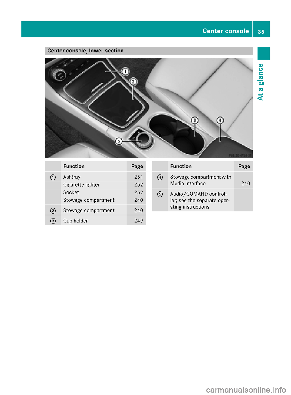
Center console, lower section
Function Page
:
Ashtray 251
Cigarette lighter 252
Socket 252
Stowage compartment 240
;
Stowage compartment 240
=
Cup holder 249 Function Page
?
Stowage compartment with
Media Interface 240
A
Audio/COMAND control-
ler; see the separate oper-
ating instructions Center console
35At a glance
Page 47 of 338
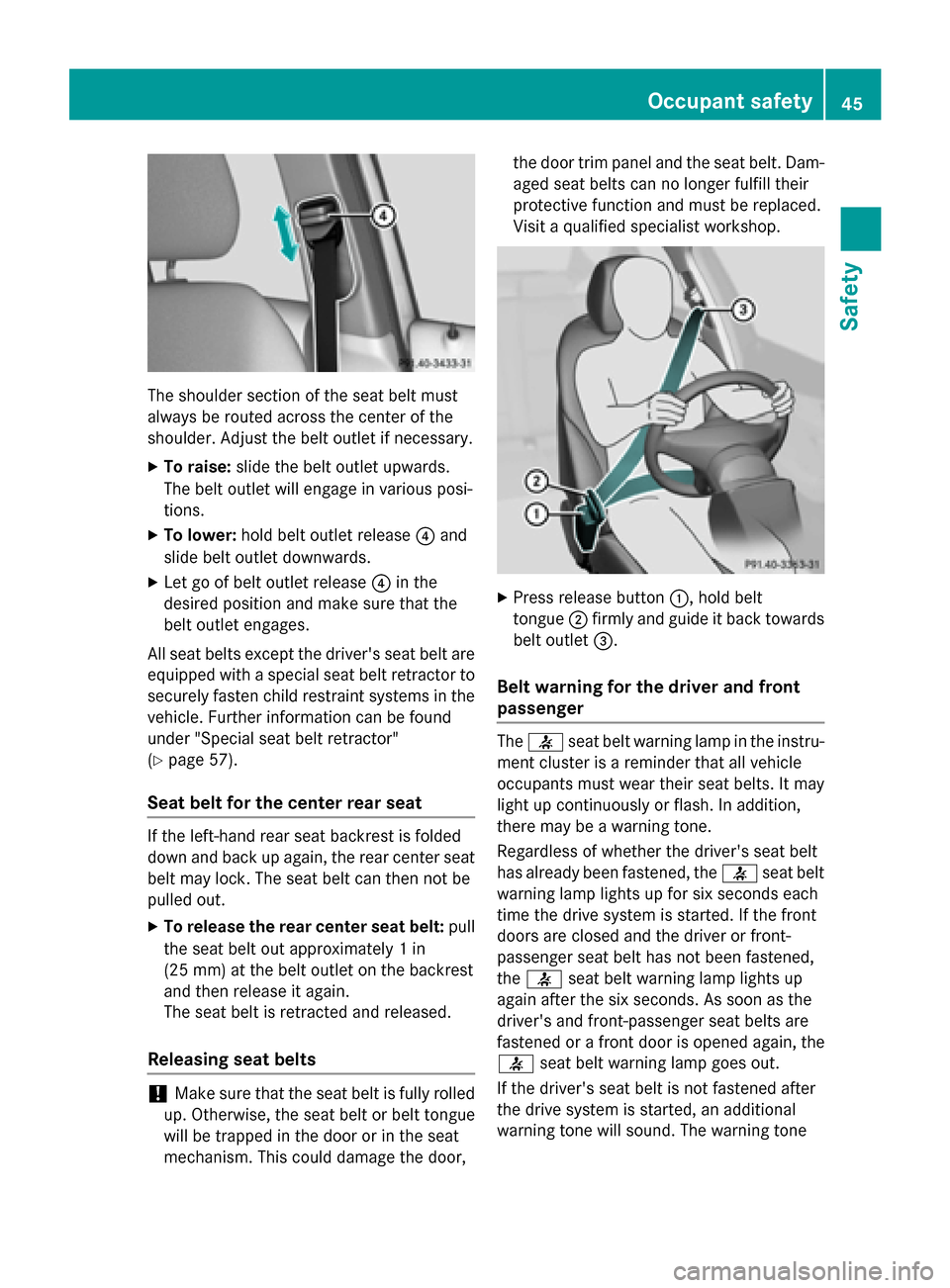
The shoulder section of the seat belt must
always be routed across the center of the
shoulder. Adjust the belt outlet if necessary.
X To raise: slide the belt outlet upwards.
The belt outlet will engage in various posi-
tions.
X To lower: hold belt outlet release ?and
slide belt outlet downwards.
X Let go of belt outlet release ?in the
desired position and make sure that the
belt outlet engages.
All seat belts except the driver's seat belt are equipped with a special seat belt retractor tosecurely fasten child restraint systems in the
vehicle. Further information can be found
under "Special seat belt retractor"
(Y page 57).
Seat belt for the center rear seat If the left-hand rear seat backrest is folded
down and back up again, the rear center seat
belt may lock. The seat belt can then not be
pulled out.
X To release the rear center seat belt: pull
the seat belt out approximately 1 in
(25 mm) at the belt outlet on the backrest
and then release it again.
The seat belt is retracted and released.
Releasing seat belts !
Make sure that the seat belt is fully rolled
up. Otherwise, the seat belt or belt tongue
will be trapped in the door or in the seat
mechanism. This could damage the door, the door trim panel and the seat belt. Dam-
aged seat belts can no longer fulfill their
protective function and must be replaced.
Visit a qualified specialist workshop. X
Press release button :, hold belt
tongue ;firmly and guide it back towards
belt outlet =.
Belt warning for the driver and front
passenger The
7 seat belt warning lamp in the instru-
ment cluster is a reminder that all vehicle
occupants must wear their seat belts. It may
light up continuously or flash. In addition,
there may be a warning tone.
Regardless of whether the driver's seat belt
has already been fastened, the 7seat belt
warning lamp lights up for six seconds each
time the drive system is started. If the front
doors are closed and the driver or front-
passenger seat belt has not been fastened,
the 7 seat belt warning lamp lights up
again after the six seconds. As soon as the
driver's and front-passenger seat belts are
fastened or a front door is opened again, the
7 seat belt warning lamp goes out.
If the driver's seat belt is not fastened after
the drive system is started, an additional
warning tone will sound. The warning tone Occupant safety
45Safety Z
Page 56 of 338
Deployment of Emergency Tensioning
Devices and air bags
Important safety notes G
WARNING
The air bag parts are hot after an air bag has
been deployed. There is a risk of injury.
Do not touch the air bag parts. Have a
deployed air bag replaced at a qualified spe-
cialist workshop as soon as possible. G
WARNING
A deployed air bag no longer offers any pro-
tection and cannot provide the intended pro-
tection in an accident. There is an increased
risk of injury.
Have the vehicle towed to a qualified special- ist workshop in order to have a deployed air
bag replaced.
It is important for your safety and that of your
passenger to have deployed air bags replaced and to have any malfunctioning air bags
repaired. This will help to make sure the air
bags continue to perform their protective
function for the vehicle occupants in the
event of a crash. G
WARNING
Pyrotechnic Emergency Tensioning Devices
that have been deployed are no longer opera- tional and are unable to perform their inten-
ded protective function. This poses an
increased risk of injury or even fatal injury.
Therefore, have pyrotechnic Emergency Ten-
sioning Devices which have been triggered
immediately replaced at a qualified specialist workshop.
If Emergency Tensioning Devices are trig-
gered or air bags are deployed, you will hear a
bang, and a small amount of powder may also be released. The 6restraint system warn-
ing lamp lights up.
Only in rare cases will the bang affect your
hearing. The powder that is released gener-
ally does not constitute a health hazard, but it may cause short-term breathing difficulties in
people with asthma or other respiratory prob-
lems. To avoid this, you may wish to get out of
the vehicle or open the windows as soon as it is safe to do so.
Air bags and pyrotechnic Emergency Tension-
ing Devices (ETDs) contain perchlorate mate- rial, which may require special handling and
regard for the environment. National guide-
lines must be observed during disposal. In
California, see www.dtsc.ca.gov/
HazardousWaste/Perchlorate/
index.cfm .
Method of operation During the first stage of a collision, the
restraint system control unit evaluates impor-
tant physical data relating to vehicle deceler- ation or acceleration, such as:
R duration
R direction
R intensity
Based on the evaluation of this data, the
restraint system control unit triggers the
Emergency Tensioning Devices during a fron- tal or rear collision.
An Emergency Tensioning Device can only be
triggered, if:
R the ignition is switched on
R the components of the restraint system are
operational; see "Restraint system warning
lamp" (Y page 41)
R the belt tongue is engaged in the buckle on
the respective front-passenger seat
The Emergency Tensioning Devices in the
rear compartment are triggered independ-
ently of the lock status of the seat belts.
If the restraint system control unit detects a
more severe accident, further components of the restraint system are activated independ-
ently of each other in certain frontal collision
situations: 54
Occupant safetySafety