radio MERCEDES-BENZ B-CLASS HATCHBACK 2011 User Guide
[x] Cancel search | Manufacturer: MERCEDES-BENZ, Model Year: 2011, Model line: B-CLASS HATCHBACK, Model: MERCEDES-BENZ B-CLASS HATCHBACK 2011Pages: 329, PDF Size: 7.91 MB
Page 227 of 329

Display messages Possible causes/consequences and
M Solutions
Blind Spot Assist
currently unavail‐
able See Owner's
Manual Blind Spot Assis
tis temporarily inoperative. Possible causes:
R you have established the electrical connection between the
trailer and your vehicle.
R the sensors are dirty.
R function is impaired due to heavy rain or snow.
R the radar sensor system is outside the operating temperature
range.
R the radar sensor system is temporarily inoperative, e.g. due to
electromagnetic radiation emitted by nearby TV or radio sta-
tions or other sources of electromagnetic radiation.
The yellow 9indicator lamps also light up in the exterior mir-
rors.
X When towing a trailer, confirm the display message with a.
If you are driving without a trailer and the displaym essage does
not disappear:
X Pull over and stop the vehicle safely as soon as possible, paying
attention to road and traffic conditions.
X Engage the electric parking brake.
X Clean the sensors (Y page 270).
X Restart the engine.
If the system detects that the sensors are fully operational, the
display message disappears.
Blind Spot Assist is operational again. Blind Spot Assist
inoperative Blind Spot Assist is faulty.
The yellow
9indicator lamps also light up in the exterior mir-
rors.
X Visit a qualified specialist workshop. Park Assist
cancelled The driver's door is open and the driver's seat belt has not been
fastened.
X
Repeat the parking process with the seat belt fastened and the
driver's door closed. You have inadvertently touched the multifunction steering wheel
while steering intervention was active.
X
While steering intervention is active, make sure that the multi-
function steering wheel is not touched. The vehicle has started to skid and ESP
®
has intervened.
X Use Active Parking Assist again later (Y page 166).224
Display messagesOn-board computer and displays
Page 229 of 329
Display messages Possible causes/consequences and
M Solutions
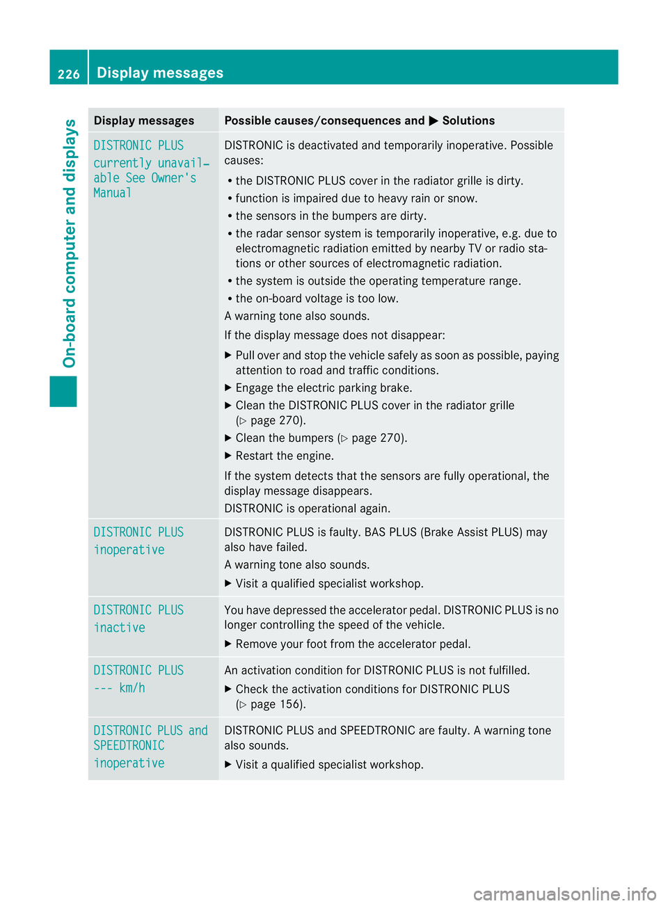
DISTRONIC PLUS
currently unavail‐
able See Owner's
Manual DISTRONIC is deactivated and temporarily inoperative. Possible
causes:
R
the DISTRONIC PLUS cover in the radiator grille is dirty.
R function is impaired due to heavy rain or snow.
R the sensors in the bumpers are dirty.
R the rada rsensor system is temporarily inoperative, e.g. due to
electromagnetic radiation emitted by nearby TV or radio sta-
tions or other sources of electromagnetic radiation.
R the system is outside the operating temperature range.
R the on-board voltage is too low.
Aw arning tone also sounds.
If the display message does no tdisappear:
X Pull over and stop the vehicle safely as soon as possible, paying
attention to road and traffic conditions.
X Engage the electric parking brake.
X Clean the DISTRONIC PLUS cover in the radiator grille
(Y page 270).
X Clean the bumpers (Y page 270).
X Restar tthe engine.
If the system detects that the sensors are fully operational, the
display message disappears.
DISTRONIC is operational again. DISTRONIC PLUS
inoperative DISTRONIC PLUS is faulty. BAS PLUS (Brake Assist PLUS) may
also have failed.
Aw
arning tone also sounds.
X Visi taqualified specialist workshop. DISTRONIC PLUS
inactive You have depressed the accelerator pedal. DISTRONIC PLUS is no
longer controlling the speed of the vehicle.
X
Remove your foot from the accelerator pedal. DISTRONIC PLUS
--- km/h An activation condition for DISTRONIC PLUS is not fulfilled.
X
Check the activation conditions for DISTRONIC PLUS
(Y page 156). DISTRONIC PLUS and
SPEEDTRONIC
inoperative DISTRONIC PLUS and SPEEDTRONIC are faulty. A warning tone
also sounds.
X
Visit a qualified specialist workshop. 226
Display messagesOn-board computer and displays
Page 262 of 329
Two-way radios and fax equipment used with-
out low-reflection exterior aerials can inter-
fere with the vehicle's electronics and thereby
jeopardise the operating safety of the vehicle
and your safety. Therefore, you must only use
this equipment if it is correctly connected to
a separate reflection-free exterior aerial. G
WARNING
Excessive levels of electromagnetic radiation
may cause damage to your health and the
health of others. Using an exterior aerial takes
into account current scientific discussions
relating to the possible health risk posed by
electromagnetic fields.
Mercedes-Benz recommends the use of an
approved exterior aerial. This ensures:
R optimal mobile phone reception quality in
the vehicle
R mutual influences between the vehicle
electronics and mobile phones are mini-
mised
An exterior aerial has the following advan-
tages:
R it conducts the electromagnetic fields gen-
erated by a wireless device to the exterior.
R the field strength in the vehicle interior is
lower than in a vehicle that does not have
an exterior aerial.
More information on suitable mobile phones,
mobile phone brackets and on connecting
Bluetooth ®
capable mobile phones to Audio
20 or COMAND Online can be obtained:
R at your Mercedes-Benz Service Centre
R on the Internet at http://www.mercedes-
benz.com/connect
i There are various mobile phone brackets
that may be fitted to your vehicle; in some
cases, these are country-specific.
i Even if your vehicle is equipped with con-
venience telephony, you can connect a
Bluetooth ®
capable mobile phone to Audio 20 or COMAND Online via the Bluetooth
®
interface.
i The functions and services available when
you use the phone depend on your mobile
phone model and service provider.
Inserting the mobile phone X
Open the telephone compartment
(Y page 246).
X Place the mobile phone bracket into the
pre-installed fitting (see the separate
installation instructions for the mobile
phone fitting).
X Insert the mobile phone into the mobile
phone bracket (see the separate installa-
tion instructions for the mobile phone fit-
ting).
If the mobile phone is inserted in the mobile
phone bracket, you can speak to the person
you are calling using the hands-free system.
i On some mobile phone brackets, you first
have to connect the mobile phone via Blue-
tooth ®
to the mobile phone bracket (see
the separate operating instructions for the
mobile phone bracket).
If this is the case, the mobile phone does
not have to be inserted into the bracket for
you to be able to use the telephone func-
tions. However, the charging function and
aerial function are not available.
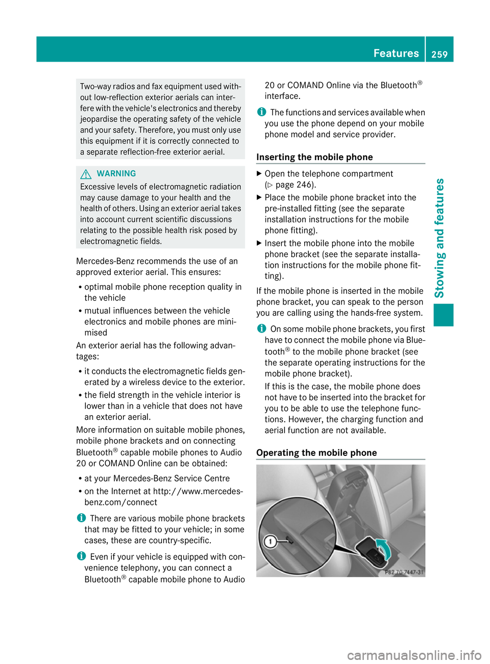
Operating the mobile phone Features
259Stowing and features Z
Page 263 of 329
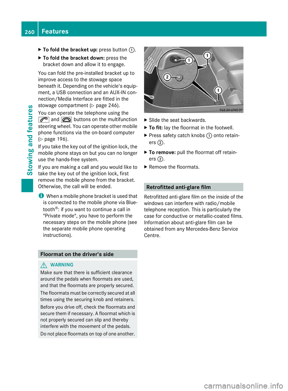
X
To fold the bracket up: press button:.
X To fold the bracket down: press the
bracket down and allow it to engage.
You can fold the pre-installed bracket up to
improve access to the stowage space
beneath it. Depending on the vehicle's equip-
ment, a USB connection and an AUX-IN con-
nection/Media Interface are fitted in the
stowage compartment (Y page 246).
You can operate the telephone using the
6 and~ buttons on the multifunction
steering wheel. You can operate othe rmobile
phone functions via the on-board computer
(Y page 196).
If you take the key out of the ignition lock, the
mobile phone stays on but you can no longer
use the hands-free system.
If you are making a call and you would like to
take the key out of the ignition lock, first
remove the mobile phone from the bracket.
Otherwise, the call will be ended.
i When a mobile phone bracket is used that
is connected to the mobile phone via Blue-
tooth ®
: if you want to continue a call in
"Private mode", you have to perform the
necessary steps on the mobile phone (see
the separate mobile phone operating
instructions). Floormat on the driver's side
G
WARNING
Make sure that there is sufficient clearance
around the pedals when floormats are used,
and that the floormats are properly secured.
The floormats must be correctly secured at all
times using the securing knob and retainers.
Before you drive off, check the floormats and
secure them if necessary. Afloormat which is
not properly secured can slip and thereby
interfere with the movemen tofthe pedals.
Do not place floormats on top of one another. X
Slide the seat backwards.
X To fit: lay the floormat in the footwell.
X Press safety catch knobs :onto retain-
ers ;.
X To remove: pull the floormat off retain-
ers ;.
X Remove the floormats. Retrofitted anti-glare film
Retrofitted anti-glare film on the inside of the
windows can interfere with radio/mobile
telephone reception. This is particularly the
case for conductive or metallic-coated films.
Information about anti-glare film can be
obtained from any Mercedes-Benz Service
Centre. 260
FeaturesStowing and features
Page 286 of 329
Jump-starting
G
WARNING
There is a risk of acid burns when jump-starting a vehicle due to the gases which escape from
the battery. Do not lean over the battery while the engine is being jump-started. G
WARNING
Gases escaping from the battery during jump-starting may cause minor explosions. Avoid cre-
ating sparks. Keep naked flames away from the battery, and do not smoke.
Comply with safety precautions when handling batteries. You will find these under "Battery (vehi-
cle)" in the index. G
WARNING
Non-combusted fuel can collect in the exhaust system and ignite. There is a risk of fire. Avoid
repeated and lengthy starting attempts.
! Avoid repeated and lengthy starting attempts. Otherwise, the catalytic converter could be
damaged by the non-combusted fuel.
Do not use a rapid charging device to start the vehicle. If your vehicle's battery is discharged,
the engine can be jump-started from another vehicle or from a second battery using jump
leads. Observe the following points:
R The battery is not accessible in all vehicles. If the other vehicle's battery is not accessible,
jump-start the vehicle using a second battery or ajump-starting device.
R You may only jump-start the vehicle when the engine and catalyti cconverter are cold.
R Do not start the engine if the battery is frozen. Let the battery thaw first.
R Jump-starting may only be performed from batteries with a nominal voltage of 12 V.
R Only use jump leads that have a sufficient cross-section and insulated terminal clamps.
R If the battery is fully discharged, leave the battery that is being used to jump-start connected
for a few minutes before attempting to start.T his charges the empty battery a little.
R Make sure that the two vehicles do not touch.
Make sure that:
R the jump leads are not damaged.
R bare parts of the terminal clamp do not come into contact with other metal parts while the
jump leads are connected to the battery.
R the jump leads cannot come into contact with parts such as the V-belt pulley or the fan.
These parts move when the engine is started and while it is running.
X Secure the vehicle by applying the electric parking brake.
X Manual transmission: engage neutral.
X Automatic transmission: shift the transmission to position P.
X Turn the key to position 0in the ignition lock and remove it.
X Switch off all electrical consumers (e.g. radio, blower, etc.).
X Open the bonnet (Y page 262). Jump-starting
283Breakdown assistance Z
Page 312 of 329
This is the case if:
R
they cause a change of the vehicle type
from that for which the vehicle's general
operating permit was granted.
R other road users could be endangered.
R the emission or noise levels are adversely
affected.
Always specify the vehicle identification num-
ber (VIN) (Y page 310) and the engine num-
ber (Y page 311) when ordering genuine
Mercedes-Benz parts. Vehicle electronics
Tampering with the engine electron-
ics
G
WARNING
Always have work on the engine electronics
and related components carried out at a quali-
fied specialist workshop. Otherwise, the vehi-
cle's operating safety could be affected.
! Only have work carried out on the engine
electronics and its associated parts, such
as control units, sensors and connector
leads, at a qualified specialist workshop.
Vehicle components may otherwise wear
more quickly and the vehicle's operating
permit may be invalidated. Retrofitting of two-way radios and
mobile phones (RF transmitters) G
WARNING
Incorrect retrofitting of RF transmitters can
cause the vehicle electronics to malfunction.
The vehicle's operating safety and thus your
own safety are impaired. Have aftermarket radio frequency transmit-
ting equipment installed at a qualified spe-
cialist workshop.
G
WARNING
Incorrect retrofitting of RF transmitters can
lead to increased electromagnetic radiation in
the vehicle interior. Using an exterior aerial
takes into account current scientific discus-
sions relating to the possible health hazards
that may result from electromagnetic fields.
Have aftermarket radio frequency transmit-
ting equipment installed at a qualified spe-
cialist workshop.
! The operating permit may be invalidated
if the instructions for installation and use of
RF transmitters are not observed.
In particular, the following conditions must
be complied with:
R only approved wavebands may be used.
R the maximum permissible output in
these wavebands must be complied with.
R the approved aerial positions must be
complied with.
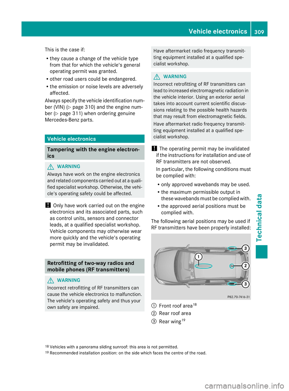
The following aerial positions may be used if
RF transmitters have been properly installed: :
Front roof area 18
; Rear roof area
= Rear wing 19
18 Vehicles with a panorama sliding sunroof: this area is not permitted.
19 Recommended installation position: on the side which faces the centre of the road. Vehicle electronics
309Technical data Z
Page 313 of 329
Use the Technical Specification
ISO/TS 21609
20
when retrofitting RF (radio
frequency) transmitters. Legal provisions for
fittings must be observed.
If your vehicle has fittings for two-way radio
equipment, use the power supply or aerial
connections intended for use with the basic
wiring. Be sure to observe the manufacturer's
additional instructions when installing.
Deviations with respect to wavebands, maxi-
mum transmission outputs or aerial positions
must be approved by Mercedes-Benz.
The maximum transmission output (PEAK) at
the base of the aerial must not exceed the
following values: Waveband Maximum
transmission
output
Short wave (f < 54 MHz) 100 W
4 m waveband 30 W
2 m waveband 50 W
Trunked radio/Tetra 35 W
70 cm waveband 35 W
GSM/DCS/PCS
850/900/1800/1900 10 W
UMTS/LTE 10 W
The following can be used in the vehicle with-
out restrictions:
R
RF transmitters with amaximum transmis-
sion output of up to 100 mW
R mobile phones (GSM/DCS/PCS/UMTS/
LTE)
There is no restriction for aerial positions in
the outer area of the vehicle for the following
wavebands:
R trunked radio/Tetra
R 70 cm waveband R
GSM/DCS/PCS
R UMTS/LTE Vehicle identification plates
Vehicle identification plate with vehi-
cle identification number (VIN) and
paint code number
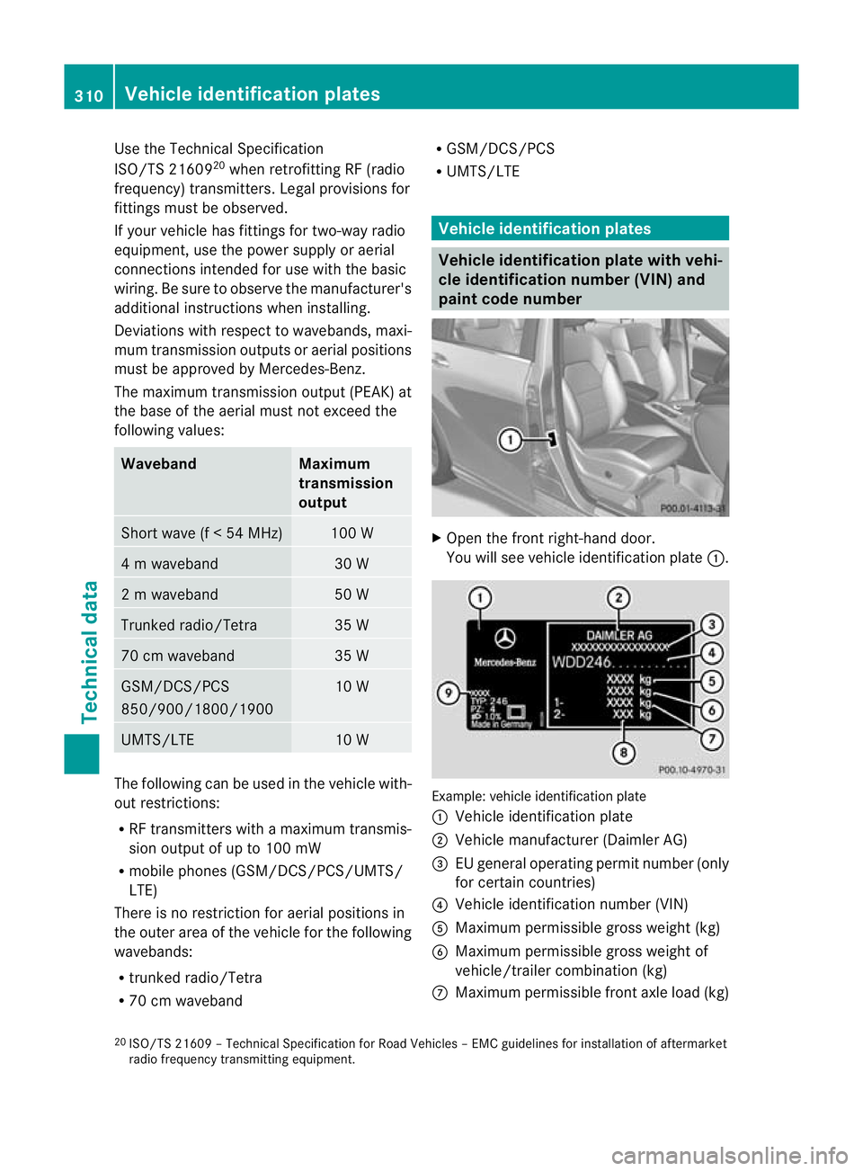
X
Open the fron tright-hand door.
You will see vehicle identification plate :. Example: vehicle identification plate
:
Vehicle identification plate
; Vehicle manufacturer (Daimler AG)
= EU general operating permit number (only
for certain countries)
? Vehicle identification number (VIN)
A Maximum permissible gross weight (kg)
B Maximum permissible gross weight of
vehicle/trailer combination (kg)
C Maximum permissible front axle load (kg)
20 ISO/TS 21609 – Technical Specification for Road Vehicles – EMC guidelines for installation of aftermarket
radio frequency transmitting equipment. 310
Vehicle identification platesTechnical data
Page 323 of 329
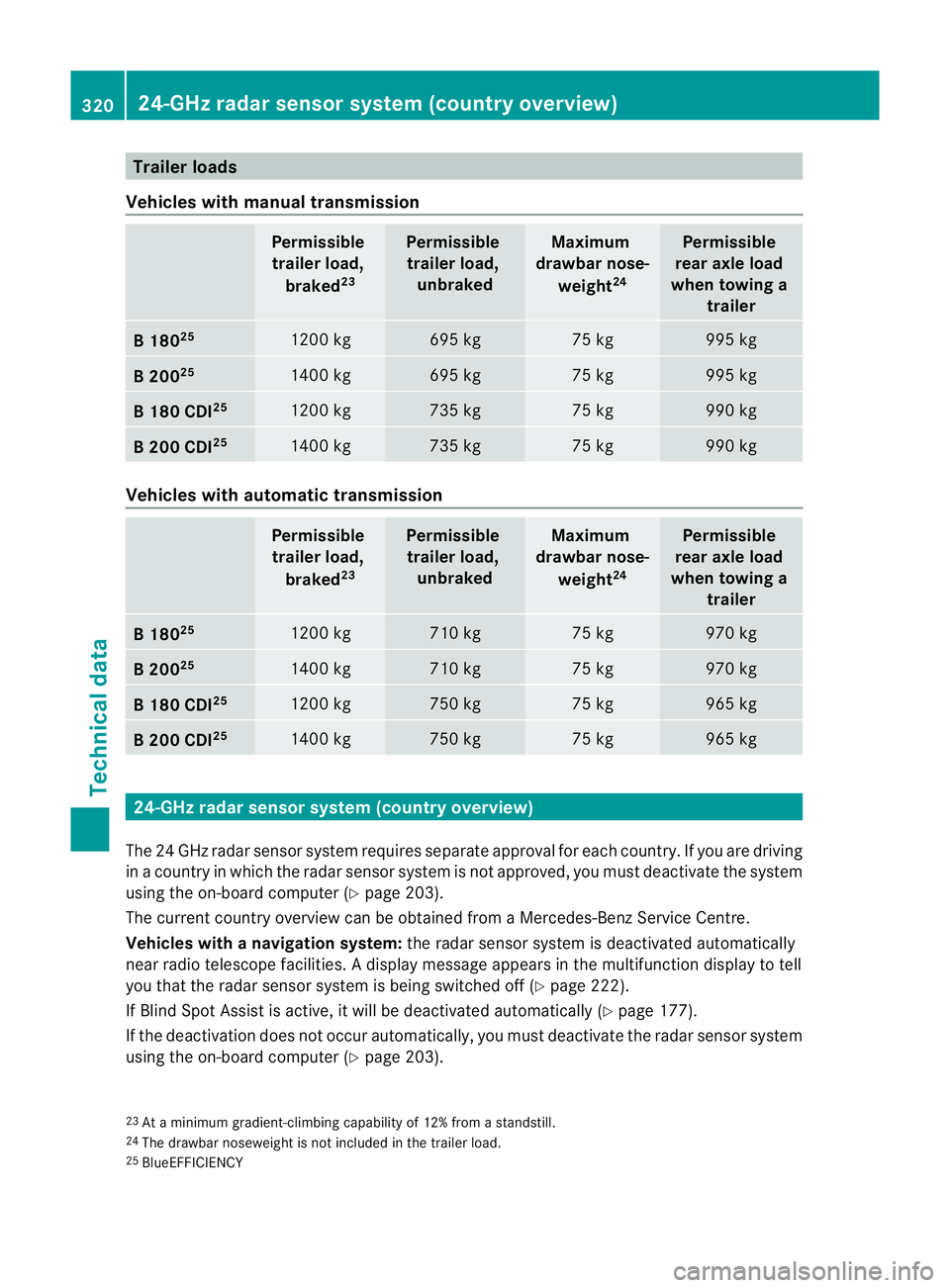
Trailer loads
Vehicles with manual transmission Permissible
trailer load,
braked 23 Permissible
trailer load, unbraked Maximum
drawbar nose-
weight 24 Permissible
rear axle load
when towing a trailer B1
8025 1200 kg 695 kg 75 kg 995 kg
B2
0025 1400 kg 695 kg 75 kg 995 kg
B1
80 CDI 25 1200 kg 735 kg 75 kg 990 kg
B2
00 CDI 25 1400 kg 735 kg 75 kg 990 kg
Vehicles with automatic transmission
Permissible
trailer load,
braked 23 Permissible
trailer load, unbraked Maximum
drawbar nose-
weight 24 Permissible
rear axle load
when towing a trailer B1
8025 1200 kg 710 kg 75 kg 970 kg
B2
0025 1400 kg 710 kg 75 kg 970 kg
B1
80 CDI 25 1200 kg 750 kg 75 kg 965 kg
B2
00 CDI 25 1400 kg 750 kg 75 kg 965 kg
24-GHz radar sensor system (country overview)
The 24 GHz radar sensor system requires separate approval for each country. If you are driving
in a country in which the radar sensor system is not approved, you must deactivate the system
using the on-board computer (Y page 203).
The current country overview can be obtained from a Mercedes-Benz Service Centre.
Vehicles with anavigation system: the radar sensor system is deactivated automatically
near radio telescope facilities. Adisplay message appears in the multifunction display to tell
you that the radar sensor system is being switched off (Y page 222).
If Blind Spot Assist is active, it will be deactivated automatically (Y page 177).
If the deactivation does not occur automatically, you must deactivate the radar sensor system
using the on-board computer (Y page 203).
23 At a minimum gradient-climbing capability of 12% fro mastandstill.
24 The drawbarn oseweight is not included in the trailer load.
25 BlueEFFICIENCY 320
24-GHz radar sensor system (country overview)Technical data
Page 324 of 329
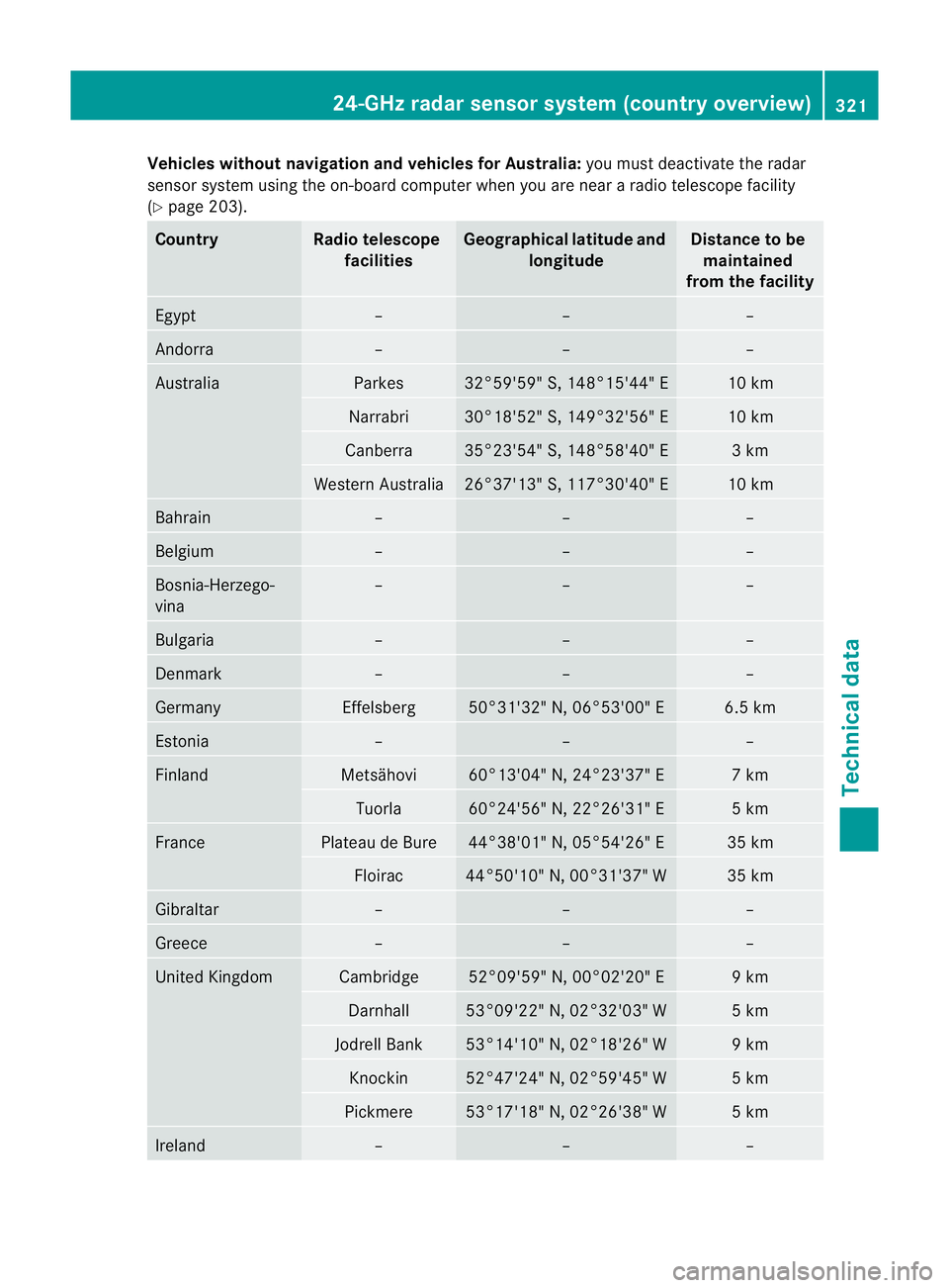
Vehicles withou
tnavigation and vehicles for Australia: you must deactivate the radar
sensor system using the on-board computer whe nyou are near a radio telescope facility
(Y page 203). Country Radio telescope
facilities Geographical latitude and
longitude Distance to be
maintained
from the facility Egypt – – –
Andorra – – –
Australia Parkes 32°59'59" S, 148°15'44" E 10 km
Narrabri 30°18'52" S, 149°32'56" E 10 km
Canberra 35°23'54" S, 148°58'40" E 3 km
Western Australia 26°37'13" S, 117°30'40" E 10 km
Bahrain – – –
Belgium – – –
Bosnia-Herzego-
vina – – –
Bulgaria – – –
Denmark – – –
Germany Effelsberg 50°31'32" N, 06°53'00" E 6.5 km
Estonia – – –
Finland Metsähovi 60°13'04" N, 24°23'37" E 7 km
Tuorla 60°24'56" N, 22°26'31" E 5 km
France Plateau de Bure 44°38'01" N, 05°54'26" E 35 km
Floirac 44°50'10" N, 00°31'37" W 35 km
Gibraltar – – –
Greece – – –
United Kingdom Cambridge 52°09'59" N, 00°02'20" E 9 km
Darnhall 53°09'22" N, 02°32'03" W 5 km
Jodrell Bank 53°14'10" N, 02°18'26" W 9 km
Knockin 52°47'24" N, 02°59'45" W 5 km
Pickmere 53°17'18" N, 02°26'38" W 5 km
Ireland – – –24-GHz radar sensor system (country overview)
321Technical data Z
Page 325 of 329
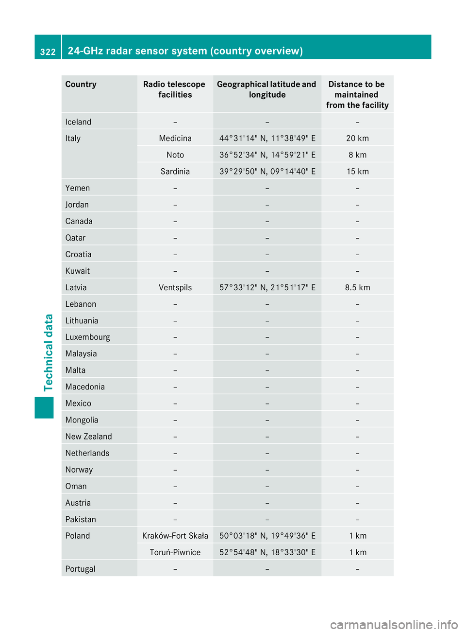
Country Radio telescope
facilities Geographica
llatitude and
longitude Distance to be
maintained
from the facility Iceland – – –
Italy Medicina 44°31'14" N, 11°38'49" E 20 km
Noto 36°52'34" N, 14°59'21" E 8 km
Sardinia 39°29'50" N, 09°14'40" E 15 km
Yemen – – –
Jordan – – –
Canada – – –
Qatar – – –
Croatia – – –
Kuwait – – –
Latvia Ventspils 57°33'12" N, 21°51'17" E 8.5 km
Lebanon – – –
Lithuania – – –
Luxembourg – – –
Malaysia – – –
Malta – – –
Macedonia – – –
Mexico – – –
Mongolia – – –
New Zealand – – –
Netherlands – – –
Norway – – –
Oman – – –
Austria – – –
Pakistan – – –
Poland Kraków-Fort Skała 50°03'18" N, 19°49'36" E 1 km
Toruń-Piwnice 52°54'48" N, 18°33'30" E 1 km
Portugal – – –322
24-GHz radar sensor system (country overview)Technical data