belt MERCEDES-BENZ B-CLASS HATCHBACK 2011 Owner's Manual
[x] Cancel search | Manufacturer: MERCEDES-BENZ, Model Year: 2011, Model line: B-CLASS HATCHBACK, Model: MERCEDES-BENZ B-CLASS HATCHBACK 2011Pages: 329, PDF Size: 7.91 MB
Page 58 of 329
R
is routed as low as possible across the pel-
vic area, in front of the hips
R is tightened across the lap by pulling
upwards on the shoulder section of the seat
belt
R is tigh tand is routed across the centre of
the child's shoulder
R is not twisted and does not pass across the
child's neck or under the child's arm
X Adjust the head restraint if necessary; see
(Y page 89).
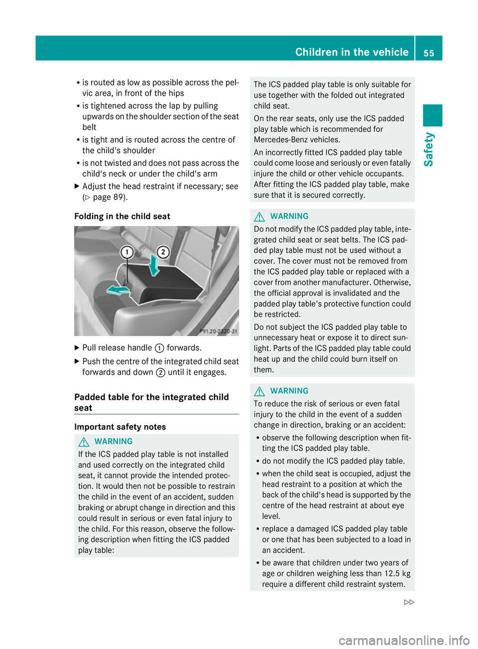
Folding in the chil dseat X
Pull release handle :forwards.
X Push the centre of the integrated child seat
forwards and down ;until it engages.
Padded table for the integrated child
seat Important safety notes
G
WARNING
If the ICS padded play table is not installed
and used correctly on the integrated child
seat, it cannot provide the intended protec-
tion. It would then not be possible to restrain
the child in the even tofanaccident, sudden
braking or abrup tchange in direction and this
could result in serious or even fatal injury to
the child. For this reason, observe the follow-
ing description when fitting the ICS padded
play table: The ICS padded play table is only suitable for
use together with the folded out integrated
child seat.
On the rear seats, only use the ICS padded
play table which is recommended for
Mercedes-Ben
zvehicles.
An incorrectly fitted ICS padded play table
could come loose and seriously or even fatally
injure the child or other vehicle occupants.
After fitting the ICS padded play table, make
sure that it is secured correctly. G
WARNING
Do not modify the ICS padded play table, inte-
grated child seat or seat belts. The ICS pad-
ded play table must not be used without a
cover. The cover must not be removed from
the ICS padded play table or replaced with a
cover from another manufacturer. Otherwise,
the official approval is invalidated and the
padded play table's protective function could
be restricted.
Do not subject the ICS padded play table to
unnecessary heat or expose it to direct sun-
light. Parts of the ICS padded play table could
heat up and the child could burn itself on
them. G
WARNING
To reduce the risk of serious or even fatal
injury to the child in the event of a sudden
change in direction, braking or an accident:
R observe the following description when fit-
ting the ICS padded play table.
R do not modify the ICS padded play table.
R when the child seat is occupied, adjust the
head restraint to a position at which the
back of the child's head is supported by the
centre of the head restraint at about eye
level.
R replace a damaged ICS padded play table
or one that has been subjected to a load in
an accident.
R be aware that children under two years of
age or children weighing less than 12.5kg
require a different child restraint system. Children in the vehicle
55Safety
Z
Page 59 of 329
Information abouto
therchild restraint sys-
tems is available from any Mercedes-Benz
Service Centre.
! Make sure that the ICS padded play table
is not trapped or damaged, for example
when you:
R close the doors
R adjust the seat
R store the ICS padded play table or trans-
port heavy objects
Use the ICS padded play table according to
the table in the "Integrated child seat" section
(Y page 53).
You should not use the integrated child seat
with an ICS padded play table in conjunction
with a baby car seat (weight category 0) for
which a body weight of up to 10 kg is permis-
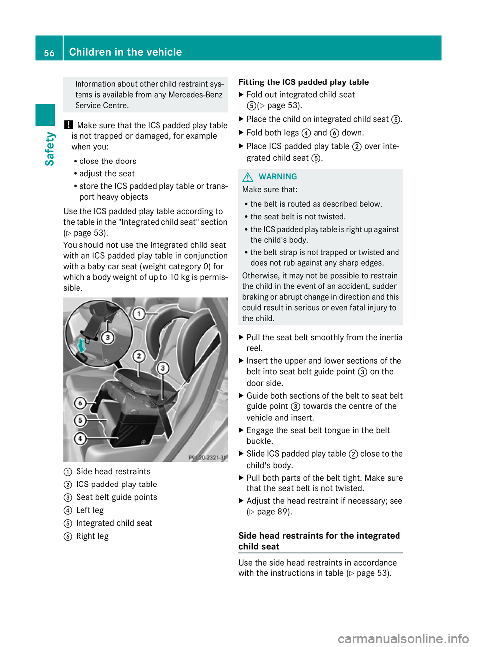
sible. :
Side head restraints
; ICS padded play table
= Seat belt guide points
? Left leg
A Integrated child seat
B Right leg Fitting the ICS padded play table
X
Fold out integrated child seat
A(Y page 53).
X Place the child on integrated child seat A.
X Fold both legs ?and Bdown.
X Place ICS padded play table ;over inte-
grated child seat A. G
WARNING
Make sure that:
R the belt is routed as described below.
R the seat belt is not twisted.
R the ICS padded play table is right up against
the child's body.
R the belt strap is not trapped or twisted and
does not rub against any sharp edges.
Otherwise, it may not be possible to restrain
the child in the event of an accident, sudden
braking or abrupt change in direction and this
could result in serious or even fatal injury to
the child.
X Pull the seat belt smoothly from the inertia
reel.
X Insert the upper and lower sections of the
belt into seat belt guide point =on the
door side.
X Guide both sections of the belt to seat belt
guide point =towards the centre of the
vehicle and insert.
X Engage the seat belt tongue in the belt
buckle.
X Slide ICS padded play table ;close to the
child's body.
X Pull both parts of the belt tight. Make sure
that the seat belt is not twisted.
X Adjust the head restraint if necessary; see
(Y page 89).
Side head restraints for the integrated
child seat Use the side head restraintsina
ccordance
with the instructions in table (Y page 53).56
Children in the vehicleSafety
Page 60 of 329

i
Should a side head restraint be required
for the second integrated child seat, this
can be ordered at any Mercedes-Benz
Service Centre. G
WARNING
If you do not secure the side head restraint at
the anchor points intended, it canno tprovide
the intended level of protection. It would then
not be possible to protect the child in the
event of an accident, sudden braking or
abrupt change in directio nand this could
result in serious or even fatal injury to the
child.
Only attach the side head restraint to the
intended anchor points on the rea rhead
restraint.
For safety reasons, Mercedes-Benz recom-
mends that you only use side head restraints
which have been approved by Mercedes-Benz
for your vehicle.
Fitting side head restraints
X Slide head restraint ;upwards and posi-
tion it upright.
X Slide side head restraints Bfrom the front
to the centre of both head restraint bars
until they engage.
Right lock verification indicator :and left
lock verification indicator =must be fol-
ded in. The red surfaces are no longer visi-
ble.
X Make sure that side head restraint Bis
engaged in both head restraint bars. X
Slide head restraint ;downwards
(Y page 89) until it rests on the upper
edge of side head restraints B.
X Guide the seat belt through seat belt guide
A on the door side on side head restraint
B.
X Secure the child (Y page 54).
i When using the integrated child seat with
the ICS padded play table, the seat belt is
not guided through the seat belt guide on
the side head restraint.
Removing the side head restraints
X Take the seat belt out of seat belt guide
A.
X Move head restraint ;upwards.
X Press left or right release button ?and pull
side head restraint Bforward to remove
it.
Right lock verification indicator :and left
lock verification indicator =fold out
briefly.
X Adjust head restraint ;(Ypage 89).
Storing the padded table and the side
head restraints G
WARNING
Secure the ICS padded play table and the side
head restraints in the vehicle as specified;
otherwise, they may come loose. In the event
of an accident, sudden braking or abrupt
change in direction, they could injure vehicle
occupants or cause damage to the vehicle.
When you are not using the ICS padded play
table and the side head restraints, store these
in a suitable place, such as the boot.
On vehicles with a TIREFIT kit, for example,
you can store the side head restraints in the
stowage compartment under the luggage
compartment floor (Y page 253). Children in the vehicle
57Safety Z
Page 61 of 329
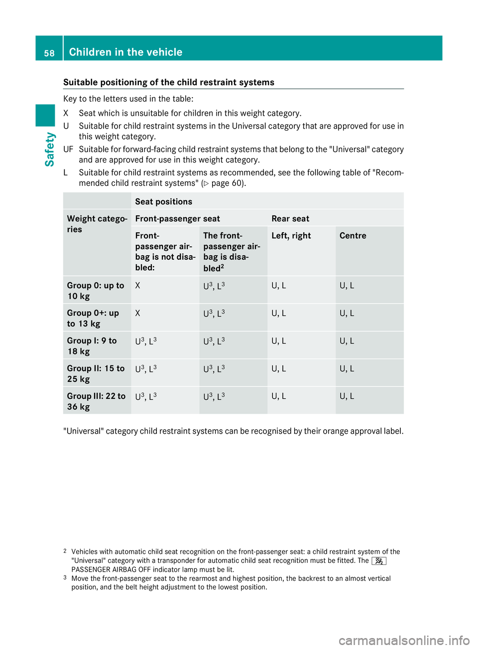
Suitable positioning of the child restraint systems
Key to the letters used in the table:
XS
eat which is unsuitable for children in this weight category.
US uitable for child restraint systems in the Universal category that are approved for use in
this weigh tcategory.
UF Suitable for forward-facing child restraint systems that belong to the "Universal" category and are approved for use in this weigh tcategory.
LS uitable for child restraint systems as recommended, see the following table of "Recom-
mended child restraint systems" (Y page 60). Sea
tpositions Weigh
tcatego-
ries Front-passenger seat Rear seat
Front-
passenge
rair-
bag is not disa-
bled: The front-
passenger air-
bag is disa-
bled
2 Left, right Centre
Group 0: up to
10 kg
X
U
3
, L 3 U, L U, L
Group 0+: up
to 13 kg
X
U
3
, L 3 U, L U, L
Group I: 9 to
18 kg
U
3
, L 3 U
3
, L 3 U, L U, L
Group II: 15 to
25 kg
U
3
, L 3 U
3
, L 3 U, L U, L
Group III: 22 to
36 kg
U
3
, L 3 U
3
, L 3 U, L U, L
"Universal" category child restraint systems can be recognised by their orange approval label.
2 Vehicles with automatic child seat recognition on the front-passenger seat: a child restraint syste mofthe
"Universal" category with a transponder for automatic child seat recognition must be fitted. The 4
PASSENGER AIRBAG OFF indicator lamp must be lit.
3 Move the front-passenger seat to the rearmost and highest position, the backrest to an almost vertical
position, and the belt height adjustment to the lowest position. 58
Children in the vehicleSafety
Page 85 of 329
Problems with the side windows
G
WARNING
Closing the side windows with increased force
or without the anti-entrapment feature could
lead to serious or even fatal injury. Make sure
that nobody can become trapped when clos-
ing the side windows.
Problem: aside window cannot be closed
because it is blocked by objects, e.g.
leaves in the window guide.
X Remove the objects.
X Close the side window.
Problem :aside window cannot be closed
and you cannot see the cause. If a side
window is obstructed during closing and
reopens again slightly:
X Immediately afte rthe window blocks, pull
the corresponding switch again until the
side window has closed.
The side window is closed with increased
force.
If a side window is obstructed again during
closing and reopens again slightly:
X Immediately after the window blocks, pull
the corresponding switch again until the
side window has closed.
The side window is closed without the anti-
entrapment feature. Sliding sunroof
Important safety notes
In the following section, the term "sliding sun-
roof" refers to the panorama sliding sunroof. G
WARNING
Make sure that nobody can become trapped
when opening and closing the sliding sunroof.
If there is a risk of entrapment, release the
switch immediately. During automatic opera-
tion, push the switch briefly in any direction
to stop the sliding sunroof. G
WARNING
Children could injure themselves if they oper-
ate the sliding sunroof.
Never leave children unsupervised in the vehi-
cle. Always take the key with you when leaving
the vehicle, even if you are only leaving it for
a short time. G
WARNING
The glass in the panorama sunroof could
break in an accident. If you are not wearing a
seat belt, there is a risk that you could be
thrown through the opening in the event of the
vehicle overturning. Therefore, always wear a
seat belt to reduce the risk of injuries.
! Only open the panorama sliding sunroof
if it is free of snow and ice. Otherwise, mal-
functions may occur.
Do not allow anything to protrude from the
sliding sunroof. Otherwise, the seals could
be damaged.
i Resonance noises can occur in addition
to the usual airflow noises when the sliding
sunroof is open. They are caused by minor
pressure fluctuations in the vehicle interior.
Change the position of the sliding sunroof
or open a side window slightly to reduce or
eliminate these noises. 82
Sliding sunroofOpening and closing
Page 89 of 329
Useful information
i This Owner's Manual describes all models
and all standard and optional equipment
available to your vehicle at the time of pub-
lication of the Owner's Manual. Country-
specific deviations are possible. Please
note that your vehicle may not be equipped
with all features described. This also
applies to safety-relevan tsystems and
functions.
i Please read the information on qualified
specialist workshops (Y page 22).Correct driver's sea
tposition Observe the safety guidelines on seat adjust-
ment (Y
page 87).
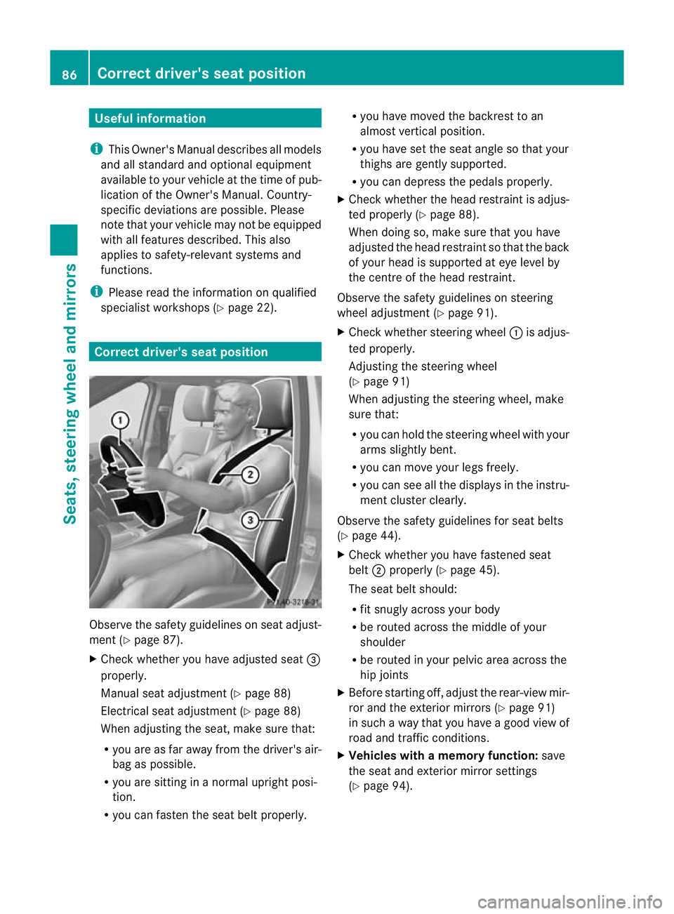
X Chec kwhether you have adjusted seat =
properly.
Manual seat adjustment (Y page 88)
Electrical seat adjustment (Y page 88)
When adjusting the seat, make sure that:
R you are as far away from the driver's air-
bag as possible.
R you are sitting in a normal upright posi-
tion.
R you can fasten the seat belt properly. R
you have moved the backrest to an
almost vertical position.
R you have set the seat angle so that your
thighs are gently supported.
R you can depress the pedals properly.
X Check whether the head restraint is adjus-
ted properly (Y page 88).
When doing so, make sure that you have
adjusted the head restraint so that the back
of your head is supported at eye level by
the centre of the head restraint.
Observe the safety guidelines on steering
wheel adjustment (Y page 91).
X Check whether steering wheel :is adjus-
ted properly.
Adjusting the steering wheel
(Y page 91)
When adjusting the steering wheel, make
sure that:
R you can hold the steering wheel with your
arms slightly bent.
R you can move your legs freely.
R you can see all the displays in the instru-
ment cluster clearly.
Observe the safety guidelines for seat belts
(Y page 44).
X Check whether you have fastened seat
belt ;properly (Y page 45).
The seat belt should:
R fit snugly across your body
R be routed across the middle of your
shoulder
R be routed in your pelvic area across the
hip joints
X Before starting off, adjust the rear-view mir-
ror and the exterior mirrors (Y page 91)
in such a way that you have a good view of
road and traffic conditions.
X Vehicles with a memory function: save
the seat and exterior mirror settings
(Y page 94). 86
Correct driver's seat positionSeats, steering wheel and mirrors
Page 90 of 329
Seats
Important safety notes
G
WARNING
The seats can still be adjusted when there is
no key in the ignition lock. For this reason,
children should never be left unsupervised in
the vehicle. They could adjust the seats and
become trapped. G
WARNING
Only adjust the driver's seat when the vehicle
is stationary. You will otherwise be distracted
from the road and traffic conditions and you
could lose control of the vehicle as a result of
the seat moving. This could cause an acci-
dent. G
WARNING
If you adjust the seat height carelessly, you or
others could be trapped and thereby injured.
Children in particular could unintentionally
press the buttons to electrically adjust the
seats and become trapped.
Take care that:
R while moving the seats, your hands do not
get under the lever assembly of the seat
adjustment system.
R children in the vehicle do not slide their
hands under the levers. G
WARNING
Make sure that nobody can become trapped
when adjusting the seats.
Observe the notes on airbags.
Secure children as recommended; see the
"Children in the vehicle" section. G
WARNING
As eat belt can only offer its intended degree
of protection when the backrest is almost ver-
tical and the occupant is sitting upright. Avoid
seat positions that do not allow the seat belt
to be routed correctly. Adjust the backrest so
that it is as upright as possible. Never travel with the backrest reclined too far backwards.
You could otherwise be seriously or even
fatally injured in the event of an accident or
sudden braking.
G
WARNING
Make sure that the back of your head is sup-
ported at eye level by the central area of the
head restraint. If your head is not supported
correctly by the head restraint, you could suf-
fer a severe neck injury in the event of an
accident. Never drive if the head restraints are
not engaged and set correctly.
! To avoid damage to the seats and the seat
heating, observe the following information:
R do not spill any liquids on the seats. If
liquid is spilled on the seats, dry them as
soon as possible.
R if the seat covers are damp or wet, do not
switch on the seat heating. The seat
heating should also not be used to dry
the seats.
R clean the seat covers as recommended;
see the "Interior care" section.
R do not transport heavy loads on the
seats. Do not place sharp objects on the
seat cushions, e.g. knives, nails or tools.
The seats should only be occupied by
passengers, if possible.
R when the seat heating is in operation, do
not cover the seats with insulating mate-
rials, e.g. blankets, coats, bags, seat cov-
ers, child seats or booster seats.
! Make sure that there are no objects in the
footwell or behind the seats when moving
the seat back. There is a risk that the seats
and/or the objects could be damaged.
i The head restraints in the fron tand rear
seats can be removed.
For more information, contact a qualified
specialist workshop. Seats
87Seats, steering wheel and mirrors Z
Page 132 of 329
The red
!indicator lamp in the instru-
ment cluster goes out.
i For further information on the electric
parking brake, see (Y page 145).
Hill starta ssist G
WARNING
Never leave the vehicle when it is held by hill
start assist. After approximately one second,
hill start assist will no longer brake your vehi-
cle and it could roll away.
Hill start assist helps you when pulling away
forwards or in reverse on an uphill gradient.
It holds the vehicle for a short time after you
have removed your foot from the brake pedal.
This gives you enough time to move your foot
from the brake pedal to the accelerator pedal
and depress it before the vehicle begins to
roll.
X Take your foot off the brake pedal.
The vehicle is then held for about a second.
X Pull away.
Hill start assist will not function if:
R you are pulling away on a level road or a
downhill gradient.
R on vehicles with automatic transmission,
the transmission is in position N.
R the electric parking brake is applied.
R ESP ®
is malfunctioning. ECO start/stop function
General notes G
WARNING
If the ECO symbol appears in the multifunc-
tion display when the engine is switched off,
the engine was switched off automatically.
However, all vehicle systems remain active. If
you open the door, unfasten your seat belt or
remove your foot from the brake pedal, the engine will automatically start
.The vehicle
may begin moving. There is a risk of accident.
To prevent the vehicle from accidentally pull-
ing away, do not release the brake pedal until
you want to drive on.
Do not leave the vehicle until you have
switched off the ignition and secured the vehi-
cle to prevent it from rolling away.
! Always switch the ignition off and take the
key with you when leaving the vehicle.
The ECO start/stop function switches the
engine off automatically if the vehicle stops
moving.
When pulling away again, the engine starts
automatically .The ECO start/stop function
thereby helps you to reduce the fuel con-
sumption and emissions of your vehicle.
The ECO start/stop function is activated each
time the engine is switched on. The system is
operational when the ¤symbol is shown
in the multifunction display.
If the ECO start/stop function is deactivated
(Y page 131), the ¤symbol is not shown.
Automatic engine switch-off General notes
The engine is only switched off if:
R
the vehicle is at a standstill (vehicles with
automatic transmission).
R in the case of vehicles with manual trans-
mission: the vehicle speed is below a cer-
tain threshold.
R the outside temperature is within the range
that is suitable for the system.
R the engine is at normal operating temper-
ature.
R the set temperature for the vehicle interior
has been reached.
R the battery is sufficiently charged.
R the system detects that the windscreen is
not misted up when the air-conditioning
system is switched on.
R the bonnet is closed. Driving
129Driving and parking Z
Page 133 of 329
R
the vehicle is not being steered.
R the driver's door is closed and the seat belt
is fastened.
i The engine can be switched off automat-
ically a maximum of four times (first stop
and three subsequent stops) in succession.
The automatic engine switch-off is then
available agai nafter the ECO symbol
appears in the multifunction display.
i During automatic engine switch-off, the
climate control system only operates at a
reduced capacity. If you require full climate
control capacity, the ECO start/stop func-
tion can be deactivated by pressing the
ECO button (Y page 131).
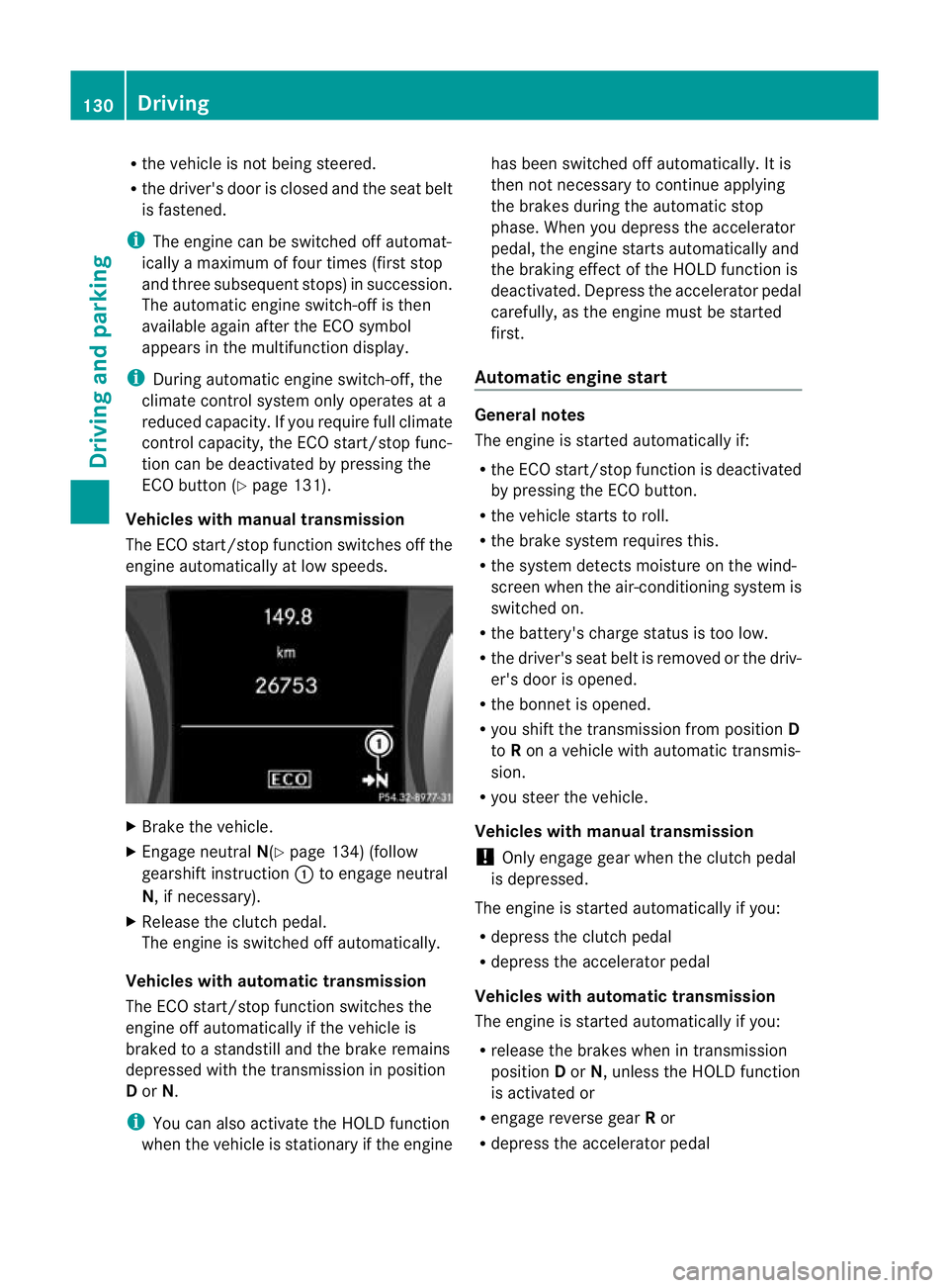
Vehicles with manual transmission
The ECO start/stop function switches off the
engine automatically at low speeds. X
Brake the vehicle.
X Engage neutral N(Ypage 134) (follow
gearshift instruction :to engage neutral
N, if necessary).
X Release the clutch pedal.
The engine is switched off automatically.
Vehicles with automatic transmission
The ECO start/stop function switches the
engine off automatically if the vehicle is
braked to a standstill and the brake remains
depressed with the transmission in position
D or N.
i You can also activate the HOLD function
whe nthe vehicle is stationary if the engine has been switched off automatically
.Itis
the nnot necessary to continue applying
the brakes during the automatic stop
phase. When you depress the accelerator
pedal, the engine starts automatically and
the braking effect of the HOLD function is
deactivated. Depress the accelerator pedal
carefully, as the engine must be started
first.
Automatic engine start General notes
The engine is started automatically if:
R
the ECO start/stop function is deactivated
by pressing the ECO button.
R the vehicle starts to roll.
R the brake system requires this.
R the system detects moisture on the wind-
screen when the air-conditioning system is
switched on.
R the battery's charge status is too low.
R the driver's seat belt is removed or the driv-
er's door is opened.
R the bonnet is opened.
R you shift the transmission from position D
to Ron a vehicle with automatic transmis-
sion.
R you steer the vehicle.
Vehicles with manual transmission
! Only engage gear when the clutch pedal
is depressed.
The engine is started automatically if you:
R depress the clutch pedal
R depress the accelerator pedal
Vehicles with automatic transmission
The engine is started automatically if you:
R release the brakes when in transmission
position Dor N, unless the HOLD function
is activated or
R engage reverse gear Ror
R depress the accelerator pedal 130
DrivingDriving and parking
Page 148 of 329
Vehicles with automatic transmission
X
Apply the electri cparking brake.
X Shift the transmission to position P.
X Turn the key to position 0in the ignition
lock and remove it.
The immobiliser is activated.
i If you switch the engine off with the trans-
mission in position Ror D, the automatic
transmission shifts to Nautomatically.
If you then open the driver's door or the
front-passenger door or remove the key
from the ignition, the automatic transmis-
sion shifts to P.
If you shift the automatic transmission to
N before switching off the engine, the auto-
matic transmission remains in Neven if a
door is opened. Electric parking brake
General notes i
The electric parking brake carries out a
function check at regular intervals when
the engine is switched off .Noises that
occur are normal.
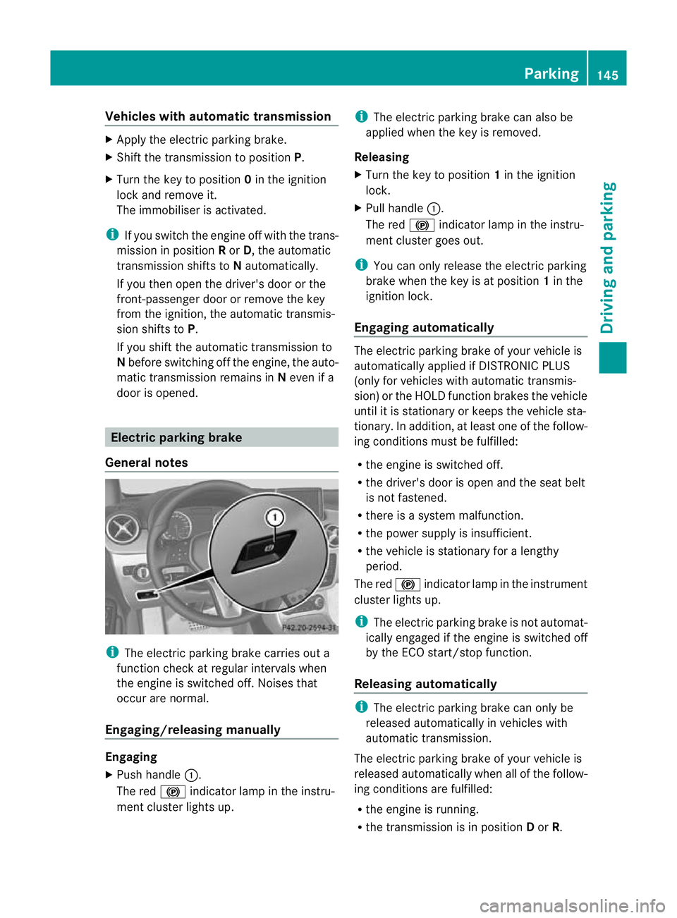
Engaging/releasing manually Engaging
X
Push handle :.
The red !indicator lamp in the instru-
ment cluster lights up. i
The electric parking brake can also be
applied when the key is removed.
Releasing
X Turn the key to position 1in the ignition
lock.
X Pull handle :.
The red !indicator lamp in the instru-
ment cluster goes out.
i You can only release the electric parking
brake when the key is at position 1in the
ignition lock.
Engaging automatically The electric parking brake of your vehicle is
automatically applied if DISTRONIC PLUS
(only for vehicles with automatic transmis-
sion) or the HOLD function brakes the vehicle
until it is stationary or keeps the vehicle sta-
tionary. In addition, at least one of the follow-
ing conditions must be fulfilled:
R
the engine is switched off.
R the driver's door is open and the seat belt
is not fastened.
R there is a system malfunction.
R the power supply is insufficient.
R the vehicle is stationary for a lengthy
period.
The red !indicator lamp in the instrument
cluster lights up.
i The electric parking brake is not automat-
ically engaged if the engine is switched off
by the ECO start/stop function.
Releasing automatically i
The electric parking brake can only be
released automatically in vehicles with
automatic transmission.
The electric parking brake of your vehicle is
released automatically when all of the follow-
ing conditions are fulfilled:
R the engine is running.
R the transmission is in position Dor R. Parking
145Driving and parking Z