tow MERCEDES-BENZ B-CLASS HATCHBACK 2011 Manual Online
[x] Cancel search | Manufacturer: MERCEDES-BENZ, Model Year: 2011, Model line: B-CLASS HATCHBACK, Model: MERCEDES-BENZ B-CLASS HATCHBACK 2011Pages: 329, PDF Size: 7.91 MB
Page 288 of 329
engine is not running. You will need more
force to steer and brake, you may have to
depress the brake pedal with maximum force.
Before towing away, make sure that the steer-
ing can be moved and is not locked.
If you tow or tow-start another vehicle, its
weight must not exceed the maximum per-
missible gross vehicle weight of your vehicle. G
WARNING
The vehicle is braked when the HOLD function
or DISTRONIC PLUS is activated. Therefore,
deactivat eHOLD and DISTRONIC PLUS if the
vehicle is to be towed.
! You may tow the vehicle for a maximum
of 50km. A towing speed of 50 km/h must
not be exceeded.
For towing distances over 50 km, the front
axle or the entire vehicle must be raised
and transported.
! Only secure the tow rope or towing bar to
the towing eyes. The vehicle may otherwise
be damaged.
! Do not use the towing eye for recovery,
as this could damage the vehicle. If in
doubt, recover the vehicle with a crane.
! Pull away smoothly when towing away or
tow-starting a vehicle. If the tractive power
is too high, the vehicles could be damaged.
! Vehicles with automatic transmission
must not be tow-started. The transmission
may otherwise be damaged.
Observe the legal requirements for the rele-
vant countries when towing and tow-starting.
It is better to have the vehicle transported
than to have it towed.
Vehicles with automatic transmission:
when towing a vehicle, the transmission must
be in position N. The battery must be connected and charged.
Otherwise, you:
R
cannot turn the key in the ignition lock to
position 2
R vehicles with automatic transmission:
cannot shift the transmission to position N
i Deactivate the automatic locking feature
(Y page 203). You could otherwise be
locked out when pushing or towing the
vehicle.
Deactivate tow-away protection
(Y page 69) before the vehicle is towed. Fitting/removing the towing eye
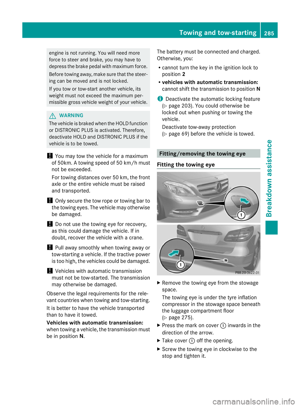
Fitting the towing eye X
Remove the towing eye from the stowage
space.
The towing eye is under the tyre inflation
compressor in the stowage space beneath
the luggage compartment floor
(Y page 275).
X Press the mark on cover :inwards in the
direction of the arrow.
X Take cover :off the opening.
X Screw the towing eye in clockwise to the
stop and tighten it. Towing and tow-starting
285Breakdown assistance Z
Page 289 of 329
Vehicles with a trailer tow hitch: if you intend
to use the vehicle for towing, fold out the ball
coupling (Y
page 183) and connect the tow-
bar to it.
Removing the towing eye X
Loosen the towing eye and unscrew it.
X Attach cover :to the bumper and press
until it engages.
X Place the towing eye and the tyre inflation
compressor in the stowage space in the
luggage compartment under the luggage
compartment floor (Y page 274).Towing the vehicle with the front axle
raised
! The ignition must be switched off if you
are towing the vehicle with the front axle
raised. Intervention by ESP ®
could other-
wise damage the brake system.
X Turn the key to position 2in the ignition
lock.
X When the vehicle is stationary, depress the
brake pedal and keep it depressed.
X Vehicles with manual transmission:
shift to neutral.
or
X Vehicles with automatic transmission:
shift the automatic transmission to posi-
tion P.
X Release the brake pedal.
X Release the electric parking brake.
X Deactivate automatic locking
(Y page 203).
X Switch on the hazard warning lamps
(Y page 99).
X Turn the key in the ignition lock to position
0and leave the key in the ignition lock.
When towing yourv ehicle with the frontaxle
raised, it is important tha tyou observe the
safety instructions (Y page 284). Towing the vehicle with both axles on
the ground
G
WARNING
The power assistance for the steering and the
brake force booster do not work when the
engine is not running. You will then need
much more effort to brake and steer the vehi-
cle. Adapt your style of driving accordingly.
i In order to signal a change of direction
when towing with the hazard warning lamps
switched on, use the combination switch as
usual.Int his case, only the turn signals for
the desired direction flash. When the com-
bination switch is reset, the hazard warning
lamps start flashing again.
Vehicles with automatic transmission: the
automatic transmission automatically shifts
to position Pwhen you open the driver's or
front-passenger door or when you remove the
key from the ignition lock. In order to ensure
that the automatic transmission stays in posi-
tion Nwhen towing the vehicle, you must
observe the following points:
X Make sure that the vehicle is stationary.
X Turn the key to position 2in the ignition
lock.
X Depress and hold the brake pedal.
X Shift the automatic transmission to posi-
tion N.
Vehicles with manual transmission:
X Turn the key to position 2in the ignition
lock.
X Depress and hold the brake pedal.
X Engage neutral.
Vehicles with manualo r automatic trans-
mission:
X Leave the key in position 2in the ignition
lock.
X Release the brake pedal.
X Release the electric parking brake.
X Switch on the hazard warning lamps
(Y page 99). 286
Towing and tow-startingBreakdown assistance
Page 290 of 329
It is important that you observe the safety
instructions when towing away yourv ehicle
(Y page 284). Transporting the vehicle
! Only lash the vehicle down by the wheels
or wheel rims, not by parts of the vehicle
such as axle or steering components. Oth-
erwise, the vehicle could be damaged.
X Vehicles with manual transmission:
shift to neutral.
X Vehicles with automatic transmission:
turn the key to position 2in the ignition
lock.
X Shift the transmission to position N.
As soon as the vehicle is loaded:
X Preven tthe vehicle from rolling away by
applying the electric parking brake.
X Vehicles with manual transmission:
shift to first gear or reverse gear.
X Vehicles with automatic transmission:
shift the transmission to position P.
X Turn the key to position 0in the ignition
lock and remove it.
X Secure the vehicle.
The towing eyes or trailer tow hitch can be
used to pull the vehicle onto a trailer or trans-
porter if you wish to transport it. Tow-starting (emergency engine
starting)
! Vehicles with automatic transmission
must not be tow-started. Otherwise, you
could damage the automatic transmission.
Before tow-starting the following conditions
must be fulfilled:
R the battery is connected.
R the engine has cooled down.
R the catalytic converters have cooled down. X
Switch on the hazard warning lamps
(Y page 99).
X Fit the towing eye (Y page 285).
X Secure the rigid towing bar or the towing
rope.
X Depress and hold the brake pedal.
X Turn the key to position 2in the ignition
lock.
X Depress the clutch pedal and keep it
depressed.
X Engage neutral.
X Release the brake pedal.
X Tow-start the vehicle.
X Engage second gear.
X Release the clutch pedal slowly without
depressing the accelerator pedal.
The engine is started.
X Depress the clutch pedal and shift to neu-
tral.
X Stop at a suitable place.
X Secure the vehicle by applying the electric
parking brake.
X Remove the rigid towing bar or towing rope.
X Remove the towing eye (Y page 286).
X Switch off the hazard warning lamps.
When tow-starting, it is important that you
observe the safety instructions (Y page 284)
and the legal requirements in each respective
country. Electrical fuses
Important safety notes
G
WARNING
Only use fuses that have been approved for
Mercedes-Ben zvehicles and which have the
correct fuse rating for the systems con-
cerned. Do not attempt to repair or bridge
faulty fuses. Using fuses which have not been
approved or attempting to repair or bridge
faulty fuses could cause the fuse to be over-
loaded and result in a fire. Have the cause Electrical fuses
287Breakdown assistance
Z
Page 300 of 329
The tyre pressure warning system does not
warn you of an incorrectly set tyre pressure.
Observe the notes on the recommended tyre
pressure (Y page 295).
The tyre pressure loss warning system does
not replace the need to regularly check your
vehicle's tyre pressures, since an even loss of
pressure on several tyres at the same time
cannot be detected by the tyre pressure loss
warning system.
The tyre pressure monitor is not able to warn
you of a sudden loss of pressure, e.g. if the
tyre is penetrated by a foreign object. In the
event of a sudden loss of pressure, bring the
vehicle to a halt by braking carefully. Avoid
abrupt steering manoeuvres.
The function of the tyre pressure loss warning
system is limited or delaye dif:
R snow chains are fitted to you rvehicle's
tyres.
R road conditions are wintry.
R you are driving on sand or gravel.
R you adopt a very sporty driving style (cor-
nering at high speeds or driving with high
rates of acceleration).
R you are towing a very heavy or large trailer.
R you are driving with a heavy load (in the
vehicle or on the roof).
Restarting the tyre pressure loss warn-
ing system Restart the tyre pressure loss warning system
if you have:
R changed the tyre pressure
R changed the wheels or tyres
R fitted new wheels or tyres
X Before restarting, consult the table of tyre
pressures on the inside of the fuel filler flap
to ensure that the tyre pressure in all four
tyres is set correctly for the respective
operating conditions.
The tyre pressure loss warning system can
only give reliable warnings if you have set
the correct tyre pressure. If an incorrect tyre pressure is set, these incorrect values
will be monitored.
X Observe the notes in the section on tyre
pressures (Y page 295).
X Make sure that the key is in position 2in
the ignition lock.
X Press the =or; button to select the
Service menu.
X Press the 9or: button to select
Tyre pressure .
X Press the abutton.
The Run Flat Indicator active Restart with OK message appears in the
multifunction display.
If you wish to confirm the restart:
X Press the abutton.
The Tyre press. now OK? message
appears in the multifunction display.
X Press the 9or: button to select
Yes .
X Press the abutton.
The Run Flat Indicator restarted message appears in the multifunction dis-
play.
After a teach-in period, the tyre pressure
loss warning system will monitor the set
tyre pressures of all four tyres.
or
If you wish to cancel the restart:
X Press the %button.
or
X If the Tyre press. now OK? message
appears, use the 9or: button to
select Cancel .
X Press the abutton.
The tyre pressure values stored at the last
restart will continue to be monitored. Tyre pressure
297Wheels and tyres Z
Page 305 of 329
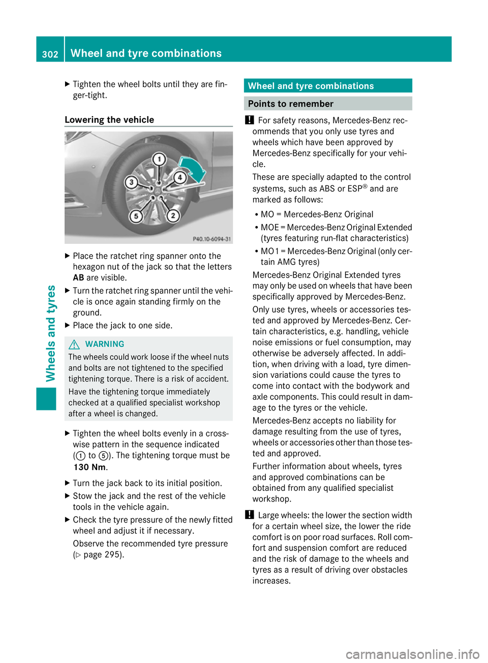
X
Tighten the wheel bolts until they are fin-
ger-tight.
Lowering the vehicle X
Place the ratchet ring spanner onto the
hexagon nut of the jack so that the letters
AB are visible.
X Turn the ratchet ring spanner until the vehi-
cle is once again standing firmly on the
ground.
X Place the jack to one side. G
WARNING
The wheels could work loose if the wheel nuts
and bolts are not tightened to the specified
tightening torque. There is a risk of accident.
Have the tightening torque immediately
checked at a qualified specialist workshop
after a wheel is changed.
X Tighten the wheel bolts evenly in a cross-
wise pattern in the sequence indicated
(: toA). The tightening torque must be
130 Nm.
X Turn the jack back to its initial position.
X Stow the jack and the rest of the vehicle
tools in the vehicle again.
X Check the tyre pressure of the newly fitted
wheel and adjust it if necessary.
Observe the recommended tyre pressure
(Y page 295). Wheel and tyre combinations
Points to remember
! For safety reasons, Mercedes-Benz rec-
ommends that you only use tyres and
wheels which have been approved by
Mercedes-Benz specifically for your vehi-
cle.
These are specially adapted to the control
systems, such as ABS or ESP ®
and are
marked as follows:
R MO =Mercedes-BenzO riginal
R MOE =Mercedes-BenzO riginal Extended
(tyres featuring run-flat characteristics)
R MO1 =Mercedes-BenzO riginal (only cer-
tain AMG tyres)
Mercedes-Benz Original Extended tyres
may only be used on wheels that have been
specifically approved by Mercedes-Benz.
Only use tyres, wheels or accessories tes-
ted and approved by Mercedes-Benz. Cer-
tain characteristics, e.g. handling, vehicle
noise emissions or fuel consumption, may
otherwise be adversely affected. In addi-
tion, when driving with aload, tyre dimen-
sion variations could cause the tyres to
come into contact with the bodywork and
axle components.T his could result in dam-
age to the tyres or the vehicle.
Mercedes-Ben zaccepts no liability for
damage resulting from the use of tyres,
wheels or accessories othe rthan those tes-
ted and approved.
Further information about wheels, tyres
and approved combinations can be
obtained from any qualified specialist
workshop.
! Large wheels: the lower the section width
for a certain wheel size, the lower the ride
comfort is on poor road surfaces. Roll com-
fort and suspension comfort are reduced
and the risk of damage to the wheels and
tyres as a result of driving over obstacles
increases. 302
Wheel and tyre combinationsWheels and tyres
Page 310 of 329
Useful information
............................308
Notes on the technical data .............308
Genuine Mercedes-Benz parts .........308
Vehicle electronics ...........................309
Vehicle identification plates ............310
Service products and capacities .....311
Vehicle data ...................................... 317
Tailgate opening dimensions ...........318
Trailer tow hitch ................................ 318
24-GHz radar sensor system (coun-
tryo verview) ..................................... 320 307Technical data
Page 317 of 329
i
Further information on country-specific
fuel properties can be obtained from oil
companies, e.g. at filling stations.
Flow improver
To improve the low-temperature resistance of
diesel fuel, a flow improve rcan be attached.
The effectiveness of a flow improve ris not
guaranteed for every fuel.
Only use flow improvers tested and approved
by Mercedes-Benz.D uringuse, please
observe the information on operation.
Correct dosage and sufficient mixing are deci-
sive in improving low-temperature resistance
with the flow improver. Overdosage can
potentially even decrease low-temperature
resistance and must therefore be avoided.
Follow the manufacturer's guidelines on dos-
age.
Mix the additive into the diesel in good time,
before the flow characteristics of the diesel
become insufficient. Otherwise, malfunctions
can arise through heating the fuel system,
e.g. through parking in a heated garage.
More information aboutr ecommended flow
improvers can be obtained from any qualified
specialist workshop.
Notes on fuel consumption H
Environmental note
CO 2(carbon dioxide) is the gas which scien-
tists believe to be principally responsible for
global warming (the greenhouse effect). Your
vehicle's CO 2emissions are directly related to
fuel consumption and therefore depend on:
R efficien tuse of the fuel by the engine
R driving style
R other non-technical factors, such as envi-
ronmental influences or road conditions
You can minimise your vehicle's CO 2emis-
sions by driving carefully and having it serv-
iced regularly. The vehicle will use more fuel than usual in
the following situations:
R
at very low outside temperatures
R in urban traffic
R on short journeys
R in mountainous terrain
R when towing a trailer
i Only for certain countries: you can find
the current consumption and emission val-
ues of your vehicle in the COC documents
(EU CERTIFICATE OF CONFORMITY). These
documents are delivered with your vehicle.
The consumption figures were in each case
based on the currently applicable version:
R for vehicles up to and including the EURO
4s tandard, in accordance with EU Direc-
tive 80/1268/EEC
R for vehicles above the EURO 5standard,
in accordance with Regulatio n(EC) No.
715/2007
Deviations fro mthese values may occur
under normal operating conditions. Engine oil
Points to remember The quality of the engine oil is decisive for the
function and service life of an engine. After
extensive tests, Mercedes-Ben
zapproves
engine oils that correspond to the current
technical standard.
Therefore, only Mercedes-Benz approved
engine oils may be used in Mercedes-Benz
engines.
Further information on tested and approved
engine oils can be obtained from any
Mercedes-Benz Service Centre. Mercedes-
Ben zrecommends that you have the oil
change carried out at a qualified specialist
workshop. Mercedes-Benza pproval is indica-
ted on the oil container by the inscription "MB
Approval" and the corresponding designa-
tion, e.g. MB Approval 229.51. 314
Service products and capacitiesTechnical data
Page 321 of 329
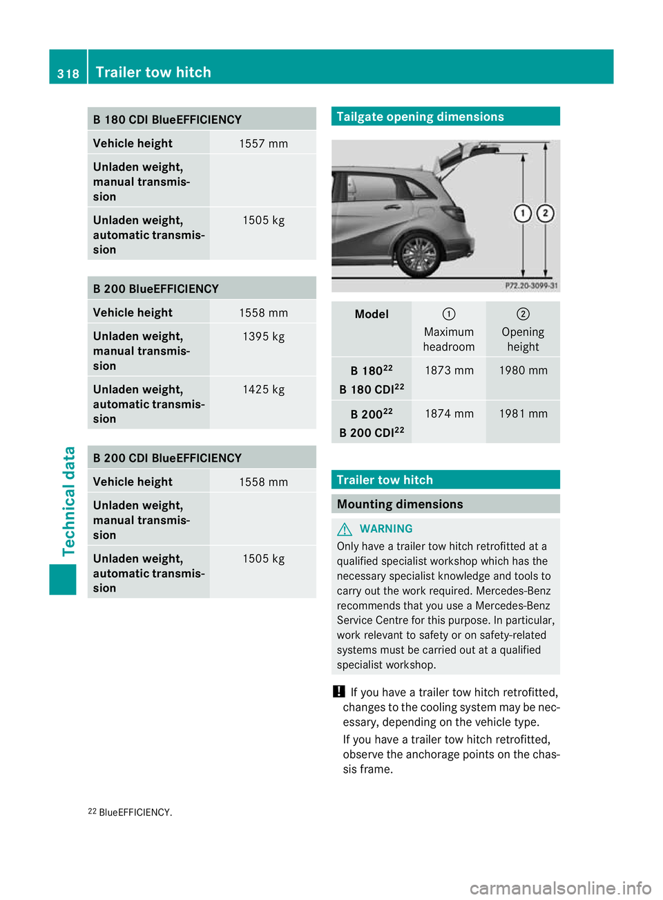
B1
80 CDI BlueEFFICIENCY Vehicle height
1557 mm
Unladen weight,
manual transmis-
sion
Unladen weight,
automatic transmis-
sion
1505 kg
B2
00 BlueEFFICIENCY Vehicle height
1558 mm
Unladen weight,
manual transmis-
sion
1395 kg
Unladen weight,
automatic transmis-
sion
1425 kg
B2
00 CDI BlueEFFICIENCY Vehicle height
1558 mm
Unladen weight,
manual transmis-
sion
Unladen weight,
automatic transmis-
sion
1505 kg Tailgate opening dimensions
Model :
Maximum
headroom ;
Opening height B1
8022
B1 80 CDI 22 1873 mm 1980 mm
B2
0022
B2 00 CDI 22 1874 mm 1981 mm
Trailer tow hitch
Mounting dimensions
G
WARNING
Only have a trailer tow hitch retrofitted at a
qualified specialist workshop which has the
necessary specialist knowledge and tools to
carry out the work required. Mercedes-Benz
recommends that you use aMercedes-Benz
Service Centre for this purpose. In particular,
work relevant to safety or on safety-related
systems must be carried out at a qualified
specialist workshop.
! If you have a trailer tow hitch retrofitted,
changes to the cooling system may be nec-
essary, depending on the vehicle type.
If you have a trailer tow hitch retrofitted,
observe the anchorage point sonthe chas-
sis frame.
22 BlueEFFICIENCY. 318
Trailer tow hitchTechnical data
Page 322 of 329
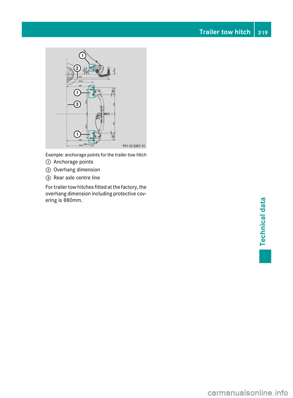
Example: anchorage points for the trailer tow hitch
:
Anchorage points
; Overhang dimension
= Rear axle centre line
For traile rtow hitches fitted at the factory, the
overhang dimension including protective cov-
ering is 880mm. Trailer tow hitch
319Technical data Z
Page 323 of 329
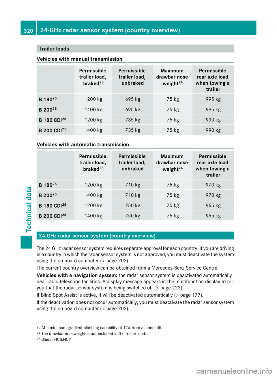
Trailer loads
Vehicles with manual transmission Permissible
trailer load,
braked 23 Permissible
trailer load, unbraked Maximum
drawbar nose-
weight 24 Permissible
rear axle load
when towing a trailer B1
8025 1200 kg 695 kg 75 kg 995 kg
B2
0025 1400 kg 695 kg 75 kg 995 kg
B1
80 CDI 25 1200 kg 735 kg 75 kg 990 kg
B2
00 CDI 25 1400 kg 735 kg 75 kg 990 kg
Vehicles with automatic transmission
Permissible
trailer load,
braked 23 Permissible
trailer load, unbraked Maximum
drawbar nose-
weight 24 Permissible
rear axle load
when towing a trailer B1
8025 1200 kg 710 kg 75 kg 970 kg
B2
0025 1400 kg 710 kg 75 kg 970 kg
B1
80 CDI 25 1200 kg 750 kg 75 kg 965 kg
B2
00 CDI 25 1400 kg 750 kg 75 kg 965 kg
24-GHz radar sensor system (country overview)
The 24 GHz radar sensor system requires separate approval for each country. If you are driving
in a country in which the radar sensor system is not approved, you must deactivate the system
using the on-board computer (Y page 203).
The current country overview can be obtained from a Mercedes-Benz Service Centre.
Vehicles with anavigation system: the radar sensor system is deactivated automatically
near radio telescope facilities. Adisplay message appears in the multifunction display to tell
you that the radar sensor system is being switched off (Y page 222).
If Blind Spot Assist is active, it will be deactivated automatically (Y page 177).
If the deactivation does not occur automatically, you must deactivate the radar sensor system
using the on-board computer (Y page 203).
23 At a minimum gradient-climbing capability of 12% fro mastandstill.
24 The drawbarn oseweight is not included in the trailer load.
25 BlueEFFICIENCY 320
24-GHz radar sensor system (country overview)Technical data