phone MERCEDES-BENZ B-CLASS HATCHBACK 2015 Owners Manual
[x] Cancel search | Manufacturer: MERCEDES-BENZ, Model Year: 2015, Model line: B-CLASS HATCHBACK, Model: MERCEDES-BENZ B-CLASS HATCHBACK 2015Pages: 293, PDF Size: 10.83 MB
Page 14 of 293
Motorway mode ............................. 101
Parking lamps ..................................98
Rear foglamp .................................. .98
Setting exterior lighting ................... 97
Side lamps ....................................... 98
Switching the daytime driving
lights on/off (on-board com-
puter) ............................................. 186
Turn signals ..................................... 99
LIM indicator lamp
Cruise control ................................ 151
Variable SPEEDTRONIC ................. 153
Limiting the speed
see SPEEDTRONIC
Loading guidelines ............................ 224
Locking
see Central locking
Locking (doors)
Automatic ........................................ 79
Emergency locking ........................... 80
From inside (central locking but-
ton) .................................................. 79
Locking centrally
see Central locking
Locking verification signal (on-
board computer) ............................... 187
Luggage compartment cover
Fitting/removing ........................... 230
Important safety notes .................. 229
Notes/function .............................. 229
Luggage compartment enlarge-
ment ................................................... 228
Luggage compartment floor
Adjusting the height ....................... 232
Important safety notes .................. 231
opening/closing ............................ 231
stowage well, under ....................... 231
Lumbar support
Adjusting the 4-way lumbar sup-
port .................................................. 90 M
M+S tyres ........................................... 268
Main-beam headlamps
Adaptive Highbeam Assist ............. 101
Changing bulb s.............................. 105
Display message ............................ 202 Switching on/of
f.............................. 99
Map (Navigation)
Switching the range on the map
on/off ............................................ 138
Matt finish (cleaning instructions) .. 244
Maximum charge current
Setting (charging cable) ................. 140
Memory card (audio) ......................... 180
Memory function ................................. 96
Mercedes-Benz emergency call
system
Switch in the overhead control
panel .............................................. 236
Mercedes-Benz Intelligent Drive
Traffic Sign Assist .......................... 166
Mercedes-Benz Service Centre
see Qualified specialist workshop
Message memory (on-board com-
puter) .................................................. 189
Messages
see Display messages
Mirror turn signal
Cleaning ......................................... 245
Mirrors
see Exterior mirrors
see Rear-view mirror
see Vanity mirror (in sun visor)
Mobile phone
Frequencies ................................... 280
Installation ..................................... 280
Menu (on-board computer) ............ 181
Notes/placing in the bracket ......... 236
Transmission output (maximum) .... 280
Mobile telephone
Pre-installed bracket ...................... 238
Modifying the programming (key) ..... 73
MOExtended tyres ............................. 250
Motorway mode ................................ 101
MP3
Operating ....................................... 180
Multifunction display
Function/note s............................. 175
Permanent display ......................... 186
Multifunction steering wheel
Operating the on-board compute r..1 74
Overview .......................................... 29 Index
11
Page 15 of 293
N
Navigation Menu (on-board computer) ............ 178
Notes on running in a new vehicle .. 125O
Occupant safety Automatic front-passenger front
airbag deactivation .......................... 42
Automatic measures after an acci-
dent ................................................. 48
Children in the vehicle ..................... 49
Important safety note s.................... 34
PASSENGER AIRBAG indicator
lamp ................................................. 35
Pets in the vehicle ........................... 61
PRE-SAFE ®
(anticipatory occu-
pant protection) ............................... 48
Restraint system introduction .......... 34
Restraint system warning lamp ........ 34
Seat belts ........................................ 35
Odometer ........................................... 176
On-board computer
Assistance graphic menu ............... 182
Assistance menu ........................... 182
Audio menu ................................... 180
Convenience submenu .................. 188
Display messages .......................... 189
Displaying a service message ........ 242
E‑CELL menu ................................. 184
Factory settings ............................. 188
Important safety notes .................. 172
Instrument cluster submenu .......... 186
Light submenu ............................... 186
Menu overview .............................. 176
Message memory .......................... 189
Navigation menu ............................ 178
Operating video DVD ..................... 180
Operation ....................................... 174
Service menu ................................. 184
Settings menu ............................... 184
Standard display ............................ 176
Telephone menu ............................ 181
Trip menu ...................................... 176
Vehicle submenu ........................... 187 Opening and closing the side trim
panels
................................................. 106
Operating instructions
Vehicle equipment ........................... 20
Operating safety
Declaration of conformity ................ 22
Important safety note ...................... 20
Operating system
see On-board computer
Outside temperature display ........... 172
Overhead control panel ...................... 33
Override feature
Rear side window s........................... 61 P
Paint code .......................................... 281
Paintwork (cleaning instructions) ... 244
Parking
Important safety notes .................. 145
Parking brake ................................ 146
Position of exterior mirror, front-
passenger side ................................. 95
Reversing camera .......................... 162
see Active Parking Assist
see PARKTRONIC
Parking aid
Active Parking Assist ..................... 158
see Exterior mirrors
see PARKTRONIC
Parking assistance
see PARKTRONIC
Parking brake
Display message ............................ 193
Electric parking brake .................... 146
Warning lamp ................................. 222
Parking lamps
Changing bulb s.............................. 106
Display message ............................ 202
Switching on/of f.............................. 98
Parking lamps (changing bulbs) ...... 106
PARKTRONIC
Deactivating/activating ................. 157
Driving system ............................... 155
Function/note s............................. 155
Important safety notes .................. 155
Problem (fault) ............................... 158
Sensor range ................................. 156 12
Index
Page 18 of 293
Snow chains
...................................... 269
Socket
Luggage compartment ...................2 36
Sockets
Centre console .............................. 235
General notes ................................ 235
Rear compartment ......................... 236
Specialist workshop ............................ 23
Spectacles compartment ................. 225
Speed, controlling
see Cruise control
Speedometer
Activating/deactivating the addi-
tional speedometer ........................ 186
Digital ............................................ 178
In the Instrument cluster ................. 27
Selecting a display unit .................. 186
SPEEDTRONIC
Deactivating variable ..................... 154
Function/notes ............................ .152
Important safety notes .................. 152
LIM indicator lamp ......................... 153
Selecting ........................................ 153
Storing the current spee d.............. 153
Variabl e......................................... 153
SPEEDTRONIC (variable)
Storing the current speed and
calling up the last stored speed ..... 153
Start/Stop button
Removing ....................................... 127
Starting the drive system ............... 127
Starting
the Vehicle ..................................... 127
Starting the vehicle. .......................... 127
STEER CONTROL .................................. 67
Steering
Display message ............................ 212
Steering assistant STEER CON-
TROL
see STEER CONTROL
Steering wheel
Adjusting (manually) ........................ 92
Button overview ............................... 29
Buttons (on-board computer) ......... 174
Cleaning ......................................... 247
Gearshift paddle s........................... 132
Important safety notes .................... 92 Steering wheel gearshift paddles
.... 132
Stowage compartment
Map pockets .................................. 227
Stowage compartments
Armrest (front) ............................... 225
Armrest (under) ............................. 226
Centre console .............................. 225
Centre console (rear) ..................... 226
Cup holde r..................................... 233
Glove compartment ....................... 225
Important safety information ......... 224
Spectacles compartment ............... 225
Under driver's seat/front-
passenger sea t.............................. 226
Stowage net ....................................... 227
Stowage space
Stowage net ................................... 227
Summer tyres .................................... 268
Sun visor ............................................ 234 T
Tail lamps see Lights
Tailgate
Display message ............................ 211
Emergency unlocking ....................... 81
Important safety notes .................... 81
Opening dimensions ...................... 284
Opening/closing (from outside) ....... 81
Technical data
Capacities ...................................... 282
Information .................................... 280
Tyres/wheels ................................. 277
Vehicle data ................................... 284
Telephone
Accepting a call (multifunction
steering wheel) .............................. 181
Display message ............................ 212
Introduction ................................... 181
Menu (on-board computer) ............ 181
Number from the phone book ........ 181
Redialling ....................................... 182
Rejecting/ending a call ................. 181
Telephone compartment ................ 226
Temperature
Outside temperature ...................... 172
Setting (climate control )................ 117 Index
15
Page 25 of 293
High-voltage switch-off device
!
The vehicle's high-voltage electrical system
must only be switched off when the vehicle is stationary by specially trained technicians.
The vehicle's high-voltage electrical system
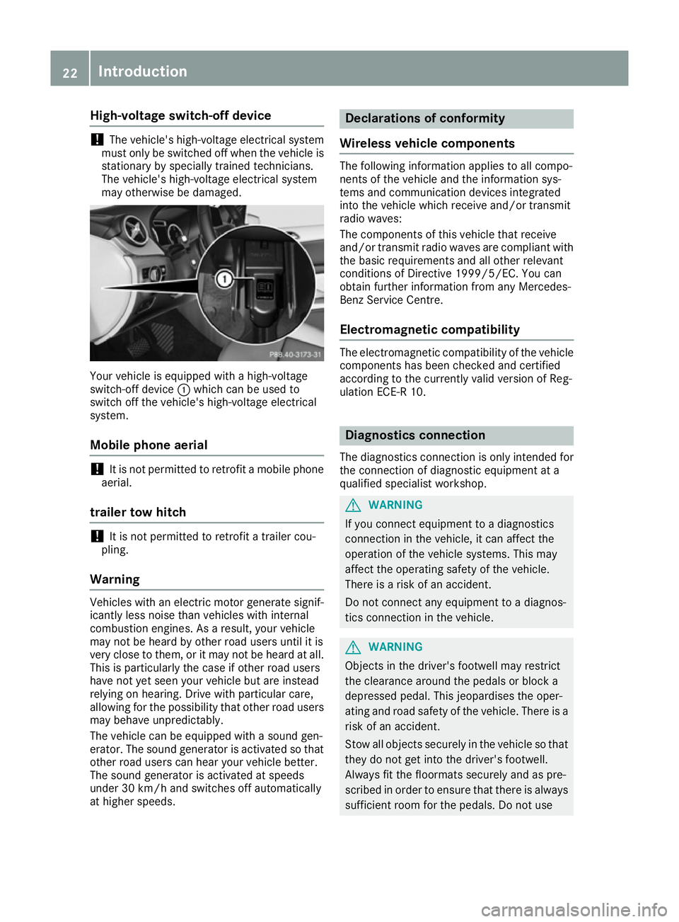
may otherwise be damaged. Your vehicle is equipped with a high-voltage
switch-off device :which can be used to
switch off the vehicle's high-voltage electrical
system.
Mobile phone aerial !
It is not permitted to retrofit a mobile phone
aerial.
trailer tow hitch !
It is not permitted to retrofit a trailer cou-
pling.
Warning Vehicles with an electric motor generate signif-
icantly less noise than vehicles with internal
combustion engines. As a result, your vehicle
may not be heard by other road users until it is
very close to them, or it may not be heard at all.
This is particularly the case if other road users
have not yet seen your vehicle but are instead
relying on hearing. Drive with particular care,
allowing for the possibility that other road users may behave unpredictably.
The vehicle can be equipped with a sound gen-
erator. The sound generator is activated so that
other road users can hear your vehicle better.
The sound generator is activated at speeds
under 30 km/h and switches off automatically
at higher speeds. Declarations of conformity
Wireless vehicle components The following information applies to all compo-
nents of the vehicle and the information sys-
tems and communication devices integrated
into the vehicle which receive and/or transmit
radio waves:
The components of this vehicle that receive
and/or transmit radio waves are compliant with
the basic requirements and all other relevant
conditions of Directive 1999/5/EC. You can
obtain further information from any Mercedes-
Benz Service Centre.
Electromagnetic compatibility The electromagnetic compatibility of the vehicle
components has been checked and certified
according to the currently valid version of Reg-
ulation ECE-R 10. Diagnostics connection
The diagnostics connection is only intended for
the connection of diagnostic equipment at a
qualified specialist workshop. G
WARNING
If you connect equipment to a diagnostics
connection in the vehicle, it can affect the
operation of the vehicle systems. This may
affect the operating safety of the vehicle.
There is a risk of an accident.
Do not connect any equipment to a diagnos-
tics connection in the vehicle. G
WARNING
Objects in the driver's footwell may restrict
the clearance around the pedals or block a
depressed pedal. This jeopardises the oper-
ating and road safety of the vehicle. There is a risk of an accident.
Stow all objects securely in the vehicle so that
they do not get into the driver's footwell.
Always fit the floormats securely and as pre-
scribed in order to ensure that there is always sufficient room for the pedals. Do not use 22
Introduction
Page 32 of 293
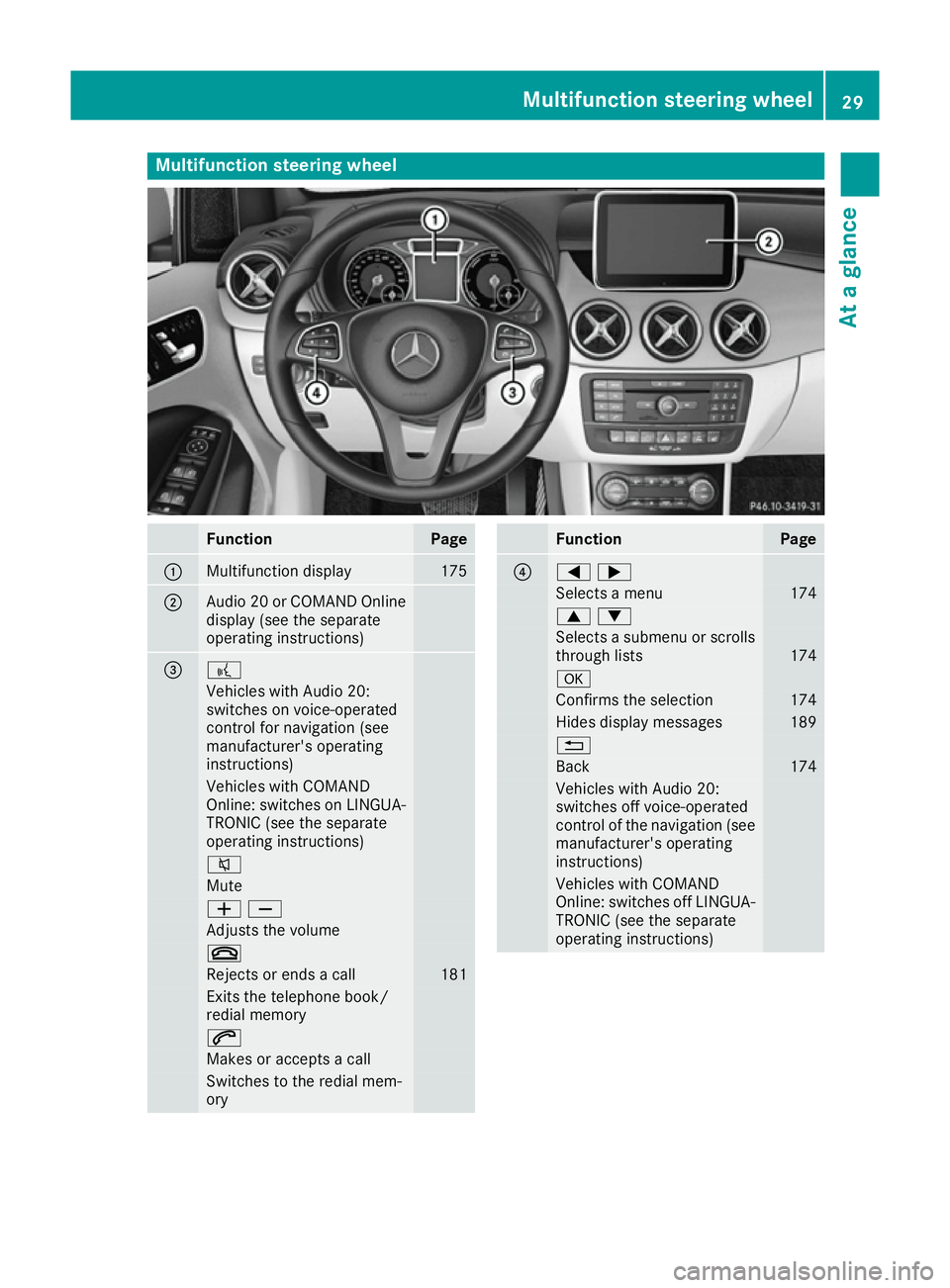
Multifunction steering wheel
Function Page
:
Multifunction display 175
;
Audio 20 or COMAND Online
display (see the separate
operating instructions) = ?
Vehicles with Audio 20:
switches on voice-operated
control for navigation (see
manufacturer's operating
instructions) Vehicles with COMAND
Online: switches on LINGUA- TRONIC (see the separate
operating instructions) 8
Mute
WX
Adjusts the volume
~
Rejects or ends a call 181
Exits the telephone book/
redial memory
6
Makes or accepts a call
Switches to the redial mem-
ory Function Page
?
=;
Selects a menu 174
9:
Selects a submenu or scrolls
through lists 174
a
Confirms the selection 174
Hides display messages 189
%
Back 174
Vehicles with Audio 20:
switches off voice-operated
control of the navigation (see
manufacturer's operating
instructions) Vehicles with COMAND
Online: switches off LINGUA-
TRONIC (see the separate
operating instructions) Multifunction steering wheel
29At a glance
Page 71 of 293
ATA (Anti-Theft Alarm system)
X
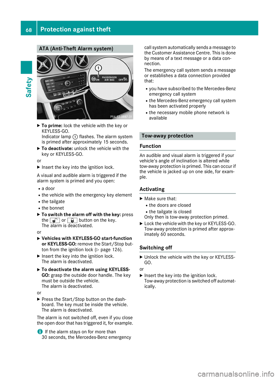
To prime: lock the vehicle with the key or
KEYLESS-GO.
Indicator lamp :flashes. The alarm system
is primed after approximately 15 seconds.
X To deactivate: unlock the vehicle with the
key or KEYLESS-GO.
or X Insert the key into the ignition lock.
A visual and audible alarm is triggered if the
alarm system is primed and you open: R a door
R the vehicle with the emergency key element
R the tailgate
R the bonnet
X To switch the alarm off with the key: press
the % or& button on the key.
The alarm is deactivated.
or X Vehicles with KEYLESS-GO start-function
or KEYLESS-GO: remove the Start/Stop but-
ton from the ignition lock (Y page 126).
X Insert the key into the ignition lock.
The alarm is deactivated.
X To deactivate the alarm using KEYLESS-
GO:
grasp the outside door handle. The key
must be outside the vehicle.
The alarm is deactivated.
or X Press the Start/Stop button on the dash-
board. The key must be inside the vehicle.
The alarm is deactivated.
The alarm is not switched off, even if you close
the open door that has triggered it, for example.
i If the alarm stays on for more than
30 seconds, the Mercedes ‑Benz emergencycall system automatically sends a message to
the Customer Assistance Centre. This is done by means of a text message or a data con-
nection.
The emergency call system sends a message
or establishes a data connection provided
that:
R you have subscribed to the Mercedes ‑Benz
emergency call system
R the Mercedes‑Benz emergency call system
has been activated properly
R the necessary mobile phone network is
available Tow-away protection
Function An audible and visual alarm is triggered if your
vehicle's angle of inclination is altered while
tow-away protection is primed. This can occur if
the vehicle is jacked up on one side, for exam-
ple.
Activating X
Make sure that:
R the doors are closed
R the tailgate is closed
Only then is tow-away protection primed.
X Lock the vehicle with the key or KEYLESS-GO.
Tow-away protection is primed after approx-
imately 60 seconds.
Switching off X
Unlock the vehicle with the key or KEYLESS-
GO.
or X Insert the key into the ignition lock.
Tow-away protection is switched off automat-
ically. 68
Protection against theftSafety
Page 74 of 293
Useful information
i This Owner's Manual describes all models,
series and optional equipment for your vehi-
cle that were available at the time of going to
press. National variations are possible. Note
that your vehicle may not be equipped with all
of the functions described. This is also the
case for systems and functions relevant to
safety.
i Read the information on qualified specialist
workshops: (Y page 23). Key
Important safety notes
G
WARNING
If children are left unsupervised in the vehicle, they could:
R open doors, thereby endangering other per-
sons or road users
R get out and be struck by oncoming traffic
R operate vehicle equipment and become
trapped, for example
In addition, the children could also set the
vehicle in motion by, for example:
R releasing the parking brake
R shifting the transmission out of park posi-
tion P
R starting the vehicle's drive system
There is a risk of an accident and injury.
When leaving the vehicle, always take the key with you and lock the vehicle. Never leave
children and animals unattended in the vehi-
cle. Keep the keys out of the reach of children. G
WARNING
If you attach heavy or large objects to the key, the key could be unintentionally turned in the
ignition lock. This could cause the engine to
be switched off. There is a risk of an accident.
Do not attach any heavy or large objects to the
key. Remove any bulky keyrings before insert-
ing the key into the ignition lock. !
Keep the key away from strong magnetic
fields. Otherwise, the remote control function could be affected.
Strong magnetic fields can occur in the vicin-
ity of powerful electrical installations.
Do not keep the key: R with electronic devices, e.g. a mobile phone
or another key
R with metallic objects, e.g. coins or metal film
R inside metallic objects, e.g. a metal case
Vehicles with KEYLESS-GO start function: do
not keep the key in the luggage compartment.
Otherwise, the key may not be detected, e.g.
when starting the drive system using the Start/
Stop button.
United Kingdom only: G
WARNING
When the double locks are activated, the
doors can no longer be opened from the
inside. People in the vehicle can no longer get out, e.g. in hazardous situations. There is a
risk of injury.
Therefore, do not leave any people unsuper-
vised in the vehicle, particularly children, eld-
erly people or people in need of special assis-
tance. Do not activate the double lock when
people are in the vehicle.
If the vehicle has been locked from the outside, the double lock function is activated as stand-
ard. It is then not possible to open the doors
from inside the vehicle. You can deactivate the
double lock function by deactivating the interior
motion sensor (Y page 69). The doors can then
be opened from the inside after the vehicle has
been locked from the outside. You can open the rear doors from inside the vehicle if they are not
secured by the child-proof locks (Y page 60).
The anti-theft alarm system is triggered if the
door is opened from the inside. Switch off the
alarm (Y page 68). G
WARNING
If persons (particularly children) are exposed
to heat or cold for a prolonged period, there is a risk of serious or even fatal injuries. Never
leave persons (particularly children) unatten-
ded in the vehicle. Key
71Opening and closing Z
Page 129 of 293
sufficient. If necessary, counteract the reduced
regenerative braking effect by applying the
brake yourself.
Before commencing your journey, ensure that
the charging cable required for charging the
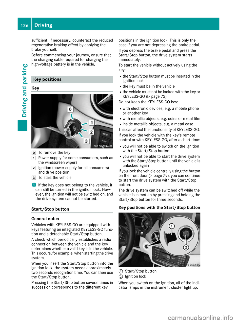
high-voltage battery is in the vehicle. Key positions
Key g
To remove the key
1 Power supply for some consumers, such as
the windscreen wipers
2 Ignition (power supply for all consumers)
and drive position
3 To start the vehicle
i If the key does not belong to the vehicle, it
can still be turned in the ignition lock. How-
ever, the ignition will not be switched on. and
the drive system cannot be started.
Start/Stop button General notes
Vehicles with KEYLESS-GO are equipped with
keys featuring an integrated KEYLESS-GO func- tion and a detachable Start/Stop button.
A check which periodically establishes a radio
connection between the vehicle and the key
determines whether a valid key is in the vehicle. This occurs, for example, when starting the drivesystem.
When you insert the Start/Stop button into the
ignition lock, the system needs approximately
two seconds recognition time. You can then use the Start/Stop button.
Pressing the Start/Stop button several times in
succession corresponds to the different key positions in the ignition lock. This is only the
case if you are not depressing the brake pedal.
If you depress the brake pedal and press the
Start/Stop button, the drive system starts
immediately.
To start the vehicle without actively using the
key:
R the Start/Stop button must be inserted in the
ignition lock
R the key must be in the vehicle
R the vehicle must not be locked with the key or
KEYLESS-GO (Y page 72)
Do not keep the KEYLESS-GO key:
R with electronic devices, e.g. a mobile phone
or another key
R with metallic objects, e.g. coins or metal film
R inside metallic objects, e.g. a metal case
This can affect the functionality of KEYLESS-GO.
If you lock the vehicle with the key's remote
control or with KEYLESS-GO, after a short time:
R you will not be able to switch on the ignition
with the Start/Stop button
R you will not be able to start the drive system
with the Start/Stop button until the vehicle is
unlocked again
If you lock the vehicle centrally using the button
on the front door (Y page 79), you can continue
to start the drive system with the Start/Stop
button.
The drive system can be switched off while the
vehicle is in motion by pressing and holding the
Start/Stop button for three seconds.
Key positions with the Start/Stop button :
Start/Stop button
; Ignition lock
When you switch on the ignition, all of the indi-
cator lamps in the instrument cluster light up. 126
DrivingDriving and parking
Page 142 of 293
Displaying the range and destination acces-
sibility via navigation mode:
X To switch to navigation mode: press the
ß button.
The map displays the current vehicle position.
or
X From one of the other main functions: slide
5 the controller (e. g. in radio mode).
The main function bar is displayed.
X To select Navi
Navi from the main function bar:
turn and press the controller.
The map displays the current vehicle position.
X To call up e-Navigator: press theßbut-
ton.
X To select Range on map Range on map in the navigation
menu: turn and press the controller.
The range and destination accessibility are
displayed on the navigation map.
To display the range and destination acces-
sibility via Mercedes-Benz Apps:
X Switch on COMAND Online/Audio 20 (see
the separate operating instructions).
X Set access data and connect to the Internet
(see separate operating instructions)
X To call up the telephone menu: press the
% button.
X To switch to the main function bar: slide 5
the controller.
X To select TEL/
TEL/®: press the controller.
X To select Internet
Internet: turn and press the con-
troller.
The menu with the Internet functions is dis-
played.
X To select Mercedes-Benz Apps
Mercedes-Benz Apps: turn and
press the controller.
The available Mercedes-Benz Apps Mercedes-Benz Apps are dis-
played.
X To call up the e-Navigator App: turn and
press the controller.
The navigation map is displayed showing the
range and destination accessibility
Showing the view levels on the map:
X To display the menu: slide6and press
the controller when the map appears.
The menu of the view levels opens. You may
choose from the following view levels: R
available charging stations
R current route
R current vehicle position with vehicle direc-
tion
Exiting the map display:
X Press the %button on the controller.
or
X To select %: slide 6and press the con-
troller. Charging the high-voltage battery via
the mains socket
Charging cable Important safety notes
! Only use the charging cable to charge the
high-voltage battery. Do not use the charging
cable for other purposes. It may otherwise be damaged.
The vehicle is supplied with a three-phase 32 A
charging cable. A single-phase 13 A charging
cable (Switzerland: 16 A) can be optionally
ordered.
When charging the vehicle using the mains
socket, use the single-phase 13 A (Switzerland:
16 A) charging cable.
Observe the "Important safety notes"
(Y page 134).
If you use the supplied 13 A charging cable
(Switzerland: 16 A) as opposed to the 32 A
charging cable to charge the high-voltage bat-
tery:
R the charge time increases considerably
R electrical consumption increases considera-
bly
For this reason, always charge the high-voltage
battery from a wallbox (Y page 142) or at a
charging station (Y page 142). Only then can
certified electrical energy consumption levels
be reached.
i The charging process can vary depending on
the charging station. Therefore, always
observe the local information. High-voltage battery
139Driving and parking Z
Page 145 of 293
i
Depending on the temperature, the engine
cooling system and battery cooling system
may audibly switch on when the charging
cable is connected or during the charging
process.
Removing the charging cable !
Before driving away, you must ensure that,
for your own safety and to avoid damage, the charging cable has been removed from the
vehicle socket. Otherwise, you cannot shift
the transmission out of position P.
When the charge level display reaches 100%,
the battery is fully charged (Y page 174).
The indicator lamps in the vehicle socket and on the charging cable may stay on for up to
30 seconds after the charging cable has been
disconnected.
When the battery is charged:
X Unlock the vehicle.
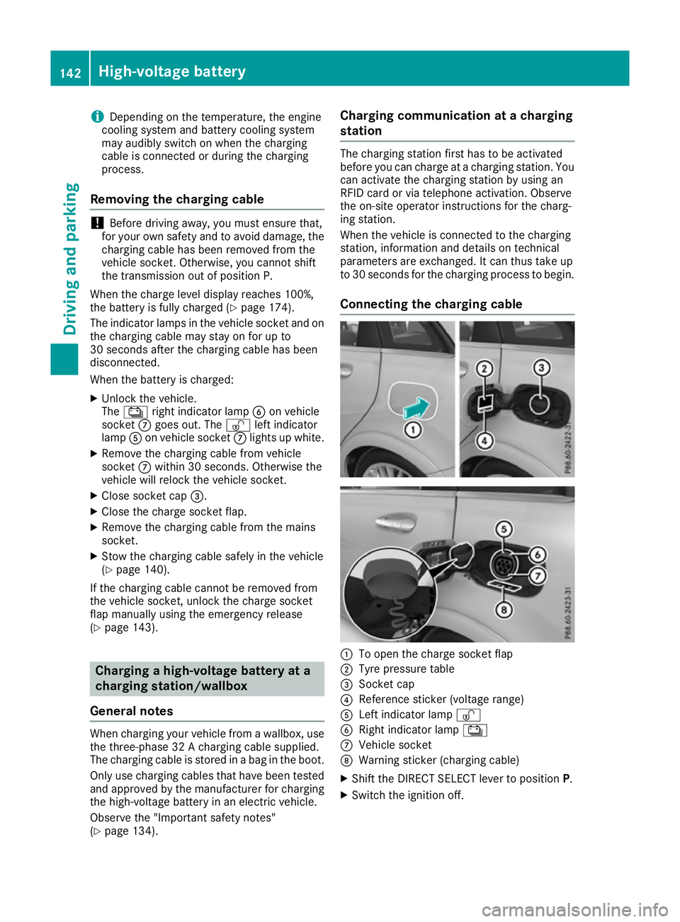
The Ý right indicator lamp Bon vehicle
socket Cgoes out. The Ìleft indicator
lamp Aon vehicle socket Clights up white.
X Remove the charging cable from vehicle
socket Cwithin 30 second s. Otherwise the
vehicle will relock the vehicle socket.
X Close socket cap =.
X Close the charge socket flap.
X Remove the charging cable from the mains
socket.
X Stow the charging cable safely in the vehicle
(Y page 140).
If the charging cable cannot be removed from
the vehicle socket, unlock the charge socket
flap manually using the emergency release
(Y page 143). Charging a high-voltage battery at a
charging station/wallbox
General notes When charging your vehicle from a wallbox, use
the three-phase 32 A charging cable supplied.
The charging cable is stored in a bag in the boot.
Only use charging cables that have been tested
and approved by the manufacturer for charging
the high-voltage battery in an electric vehicle.
Observe the "Important safety notes"
(Y page 134). Charging communication at a charging
station The charging station first has to be activated
before you can charge at a charging station. You
can activate the charging station by using an
RFID card or via telephone activation. Observe
the on-site operator instructions for the charg-
ing station.
When the vehicle is connected to the charging
station, information and details on technical
parameters are exchanged. It can thus take up
to 30 seconds for the charging process to begin.
Connecting the charging cable :
To open the charge socket flap
; Tyre pressure table
= Socket cap
? Reference sticker (voltage range)
A Left indicator lamp Ì
B Right indicator lamp Ý
C Vehicle socket
D Warning sticker (charging cable)
X Shift the DIRECT SELECT lever to position P.
X Switch the ignition off. 142
High-voltage batteryDriving and parking