ignition MERCEDES-BENZ C-CLASS 1999 Owners Manual
[x] Cancel search | Manufacturer: MERCEDES-BENZ, Model Year: 1999, Model line: C-CLASS, Model: MERCEDES-BENZ C-CLASS 1999Pages: 122, PDF Size: 1.66 MB
Page 3 of 122

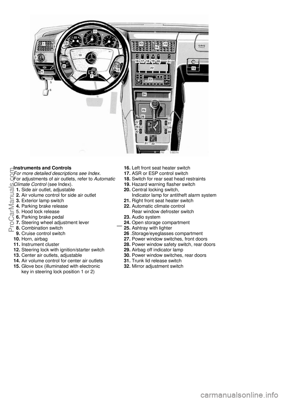
Instruments and Controls
For more detailed descriptions see Index.
For adjustments of air outlets, refer to Automatic
Climate Control (see Index).
1. Side air outlet, adjustable
2. Air volume control for side air outlet
3. Exterior lamp switch
4. Parking brake release
5. Hood lock release
6. Parking brake pedal
7. Steering wheel adjustment lever
8. Combination switch
9. Cruise control switch
10. Horn, airbag
11. Instrument cluster
12. Steering lock with ignition/starter switch
13. Center air outlets, adjustable
14. Air volume control for center air outlets
15. Glove box (illuminated with electronic
key in steering lock position 1 or 2)
16. Left front seat heater switch
17. ASR or ESP control switch
18. Switch for rear seat head restraints
19. Hazard warning flasher switch
20. Central locking switch,
Indicator lamp for antitheft alarm system
21. Right front seat heater switch
22. Automatic climate control
Rear win dow defroster switch
23. Audio system
24. Open storage compartment
25. Ashtray with lighter
26 .Storage/eyeglasses compartment
27. Power window switches, front doors
28. Power window safety switch, rear doors
29. Airbag off indicator lamp
30. Power window switches, rear doors
31. Trunk lid release switch
32. Mirror adjustment switch
ProCarManuals.com
Page 38 of 122

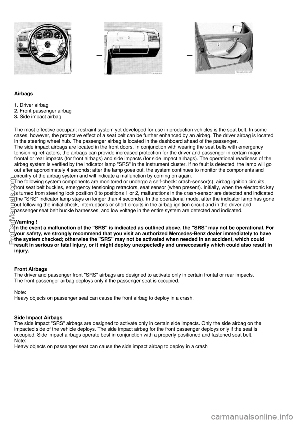
Airbags
1. Driver airbag
2. Front passenger airbag
3. Side impact airbag
The most effective occupant restraint system yet developed fo
r use in production vehicles is the seat belt. In some
cases, however, the protective effect of a seat belt can be further enhanced by an airbag. The driver airbag is located
in the steering wheel hub. The passenger airbag is located in the dashboard ahead of the passenger.
The side impact airbags are located in the front doors. In conjunction with wearing the seat belts with emergency
tensioning retractors, the airbags can provide increased protection for the driver and passenger in certain major
frontal or rear impacts (for front airbags) and side impacts (for side impact airbags). The operational readiness of the
airbag system is verified by the indicator lamp "SRS" in the instrument cluster. If no fault is detected, the lamp will go
out after approximately 4 seconds; after the lamp goes out, the system continues to monitor the components and
circuitry of the airbag system and will indicate a malfunction by coming on again.
The following system components are monitored or undergo a self-check: crash-sensor(s), airbag ignition circuits,
front seat belt buckles, emergency tensioning retractors, seat sensor (when present). Initially, when the electronic key
is turned from steering lock position 0 to positions 1 or 2, malfunctions in the crash-sensor are detected and indicated
(the "SRS" indicator lamp stays on longer than 4 seconds). In the operational mode, after the indicator lamp has gone
out following the initial check, interruptions or short circ uits in the airbag ignition circuit and in the driver and
passenger seat belt buckle harnesses, and low voltage in the entire system are detected and indicated.
Warning !
In the event a malfunction of the "SRS" is indicated as outlined above, the "SRS" may not be operational. For
your safety, we strongly recommend that you visit an authorized Mercedes-Benz dealer immediately to have
the system checked; otherwise the "SRS" may not be activated when needed in an accident, which could
result in serious or fatal injury, or it might deploy unexpectedly and unneccesarily which could also result in
injury.
Front Airbags
The driver and passenger front "SRS" airbags are designed to activate only in certain frontal or rear impacts.
The front passenger airbag deploys only if the passenger seat is occupied.
Note:
Heavy objects on passenger seat can cause the front airbag to deploy in a crash.
Side Impact Airbags
The side impact "SRS" airbags are designed to activate onl y in certain side impacts. Only the side airbag on the
impacted side of the vehicle deploys. The side impact ai rbag for the front passenger deploys only if the seat is
occupied. Side impact airbags operate best in conjunct ion with a properly positioned and fastened seat belt.
Note:
Heavy objects on passenger seat can cause the side impact airbag to deploy in a crash
ProCarManuals.com
Page 79 of 122

Hood
To open:
To unlock the hood, pull release lever (1) under the driver's
side of the instrument panel. At the same time handle
(2) will extend out of the radiator grill (it may be necessary to lift the hood up slightly).
Caution !
To avoid damage to the windshield wiper or hood, open the hood only with wiper in the parked position. Pull handle
(2) completely out of radiator grill and open hood (do not pull up on handle).
To close:
Lower hood and let it drop into lock from a height of approx. 1 ft. (30 cm), assisting with hands pl aced flat on edges
of hood (3). To avoid hood damage, if hood is not fully cl osed, repeat closing procedure. Do not push down on hood
to attempt to fully close it.
Warning!
To help prevent personal injury, stay clear of moving parts when the hood is open and the engine is running.
Be sure the hood is properly closed before driving. When closing hood, use extreme caution not to catch
hands or fingers. The engine is equipped with a transi storized ignition system. Because of the high voltage it
is dangerous to touch any components (ignition coils , spark plug sockets, diagnostic socket) of the ignition
system
• with the engine running,
• while starting the engine,
• if ignition is "on" and the engine is turned manually.
If you see flames, steam or smoke coming from the engi ne compartment, or if the coolant temperature
gauge indicates that the engine is overheated, do not open the hood. Move away from vehicle and do not
open the hood until the engine has cooled. If necessary, call a fire department.
ProCarManuals.com
Page 90 of 122

Exterior Lamps
Headlamp Adjustment
Correct headlamp adjustment is extremely important. Check and readjust headlamps at regular intervals and
when a bulb has been replaced.
Headlamp Assembly
1. Cover for low beam headlamp bulb, fog lamp, and level for vertical adjustment
2. Latch for cover (1)
3. Cover for high beam headlamp bulb
4. Clamp for cover (3)
5. Headlamp vertical adjustment screw
6. Headlamp horizontal adjustment screw
7. Scale for horizontal adjustment
8. Electrical connector for low beam headlamp bulb Xenon lamp (optional) ignition module for low beam
9. Electrical connector for fog lamp bulb
10. Electrical connector for high beam headlamp bulb
Replacing Bulb:
To prevent a possible electrical short circuit, switch off lamp prior to replacing a bulb. When replacing bulbs,
install only 12 volt bulbs with the specified watt rati ng. When replacing halogen bulbs do not touch glass
portion of bulb with bare hands. Us e plain paper or a clean cloth.
Warning !
Halogen lamps contain pressurized gas. A bulb can explode if you:
• touch or move it when hot,
• drop the bulb,
• scratch the bulb.
Wear eye and hand protection.
Bulb for Low Beam H7 (55 W)
Bulb for Fog Lamp H1 (55 W)
Open hood.
Depress latch (2) and remove cover (1). Pull of electrical connector (8) or (9). Unhook clamping ring and
removes bulb. Insert new bulb (seating properly in cutouts of bulb socket), and mount clamping ring.
Reinstall and push electrical connector on securely. Re install bottom end of cover (1) and push against top
end of cover until properly seated. Check lamp for proper operation.
Xenon (optional)
Bulb for Low Beam
Warning !
Because of high voltage in Xenon lamps, it is dangerous to replace the bulb or repair the lamp and its
components. We recommend that you have such work done by a qualified technician.
ProCarManuals.com