lamp MERCEDES-BENZ C-Class 2000 W202 Service Manual
[x] Cancel search | Manufacturer: MERCEDES-BENZ, Model Year: 2000, Model line: C-Class, Model: MERCEDES-BENZ C-Class 2000 W202Pages: 130, PDF Size: 2.43 MB
Page 81 of 130
Electronic Stability Program (ESP) (optional)
The ESP enhances directional control and reduces driving wheel spin of the vehicle under any driving condition.
Over/understeering of the vehicle is counteracted by applying brakes to the appropriate wheel to create a
counterpointing vehicle movement. The ESP warning lamp, located in the speedometer dial, starts to flash.
Important !
If the ESP warning lamp flashes, adapt your speed and driving to the prevailing road conditions.
Caution !
If the vehicle is towed with the front axle raised (see Towing the vehicle in Index), the engine must be shut off
(electronic key in steering lock position 0 or 1). Otherwise, the ESP will immediately be engaged and will apply
the rear wheel brakes.
Notes:
The indicator lamp for the ESP is combined with that of the BAS. The yellow BAS/ESP malfunction indicator lamp
in the instrument cluster and the yellow ESP warning lamp in the speedometer dial come on with the electronic key
in steering lock position 2. They should go out with the engine running. If the BAS/ESP multifunction indicator lamp
comes on permanently with the engine running, a malfunction has been detected in either system.
Pressing the accelerator pedal will require greater effort. Only partial engine output will be available. If the BAS
malfunctions, the brake system functions in the usual manner, but without BAS. Have the BAS or ESP checked at
your authorized Mercedes-Benz dealer as soon as possible. With the ABS malfunctioning, the ESP is also switched
off. Driving the vehicle with varied size tires will cause the wheels to rotate at different speeds, therefore the electronic
stability program may activate (yellow ESP warning lamp in speedometer dialcomes on).
For this reason, all wheels, including the spare wheel, must have the same tire size. When testing the parking brake
on a brake test dynamometer, the engine must be shut off. Otherwise, the electronic stability program will
immediately
be engaged and will apply the rear wheel brakes. In winter operation, the maximum effectiveness of the ESP is only
achieved with Mercedes-Benz recommended M+S rated radial-ply tires and/or snow chains.
Synchronizing ESP
If the power supply was interrupted(battery disconnected or empty), the BAS/ESP multifunction indicator lamp
may be illuminated with the engine running. Turn steering wheel completely to the left and then to the right. The
BAS/ESP malfunction indicator lamp should go out.
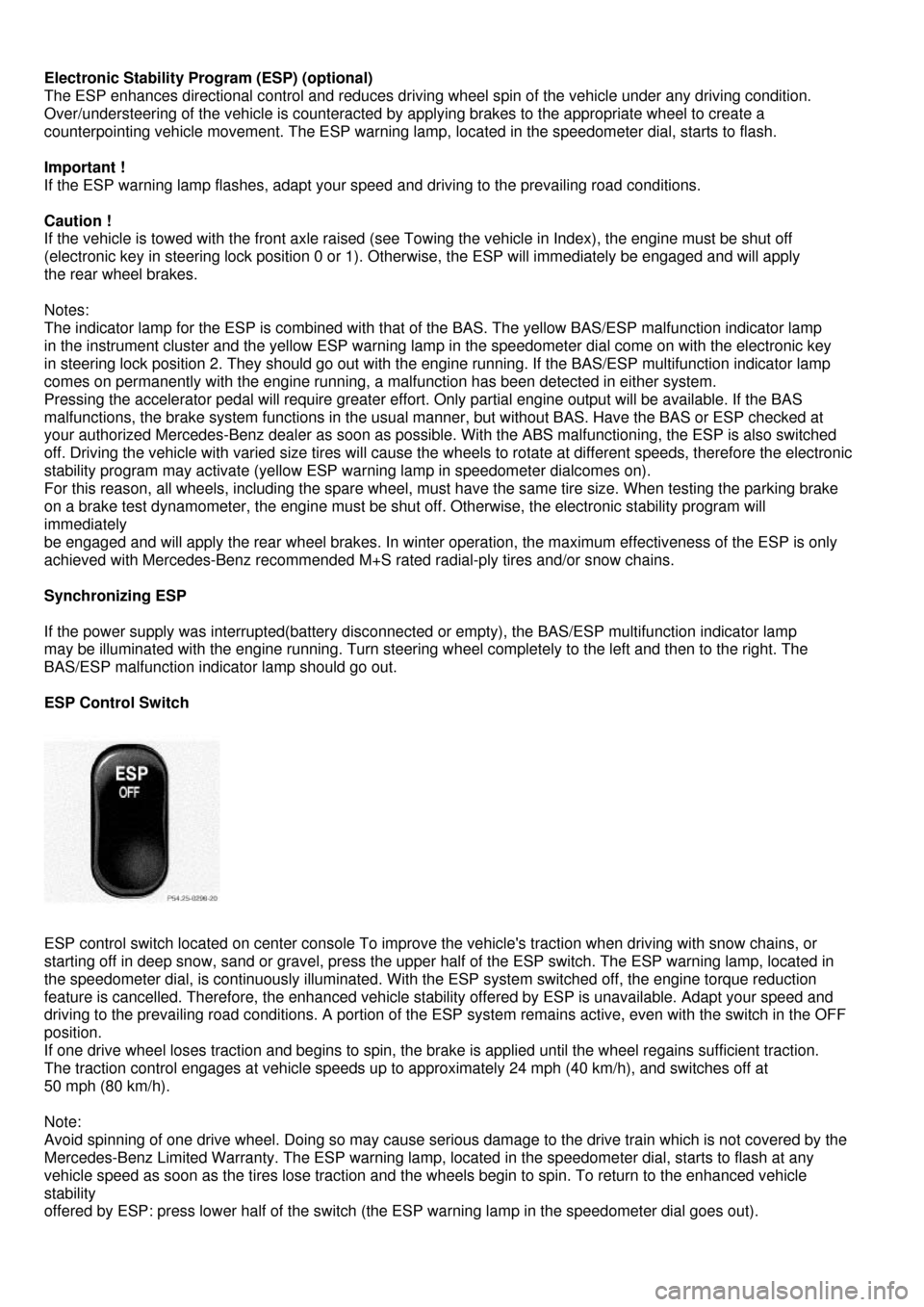
ESP Control Switch
ESP control switch located on center console To improve the vehicle's traction when driving with snow chains, or
starting off in deep snow, sand or gravel, press the upper half of the ESP switch. The ESP warning lamp, located in
the speedometer dial, is continuously illuminated. With the ESP system switched off, the engine torque reduction
feature is cancelled. Therefore, the enhanced vehicle stability offered by ESP is unavailable. Adapt your speed and
driving to the prevailing road conditions. A portion of the ESP system remains active, even with the switch in the OFF
position.
If one drive wheel loses traction and begins to spin, the brake is applied until the wheel regains sufficient traction.
The traction control engages at vehicle speeds up to approximately 24 mph (40 km/h), and switches off at
50 mph (80 km/h).
Note:
Avoid spinning of one drive wheel. Doing so may cause serious damage to the drive train which is not covered by the
Mercedes-Benz Limited Warranty. The ESP warning lamp, located in the speedometer dial, starts to flash at any
vehicle speed as soon as the tires lose traction and the wheels begin to spin. To return to the enhanced vehicle
stability
offered by ESP: press lower half of the switch (the ESP warning lamp in the speedometer dial goes out).
Page 82 of 130

Important !
If the ESP warning lamp flashes:
• during take-off, apply as little throttle as possible,
• while driving, ease up on the accelerator.
Page 83 of 130

Emission Control
Certain systems of the engine serve to keep the toxic components of the exhaust gases within permissible limits
required by law. These systems, of course, will function properly only when maintained strictly according to factory
specifications. Any adjustments on the engine should, ther efore, be carried out only by qualified Mercedes-Benz
authorized dealer technicians. Engine adjustments should not be altered in any way. Moreover, the specified service
jobs must be carried out regularly according to Mercedes -Benz servicing requirements. For details refer to the
Service Booklet.
Warning !
Inhalation of exhaust gas is hazardous to your health. All exhaust gas contains carbon monoxide, and
inhaling it can cause unconsciousness and lead to death.
Do not run the engine in confined areas (such as a garage) which are not properly ventilated.
If you think that exhaust gas fumes are entering the vehicle while driving, have the cause determined and
corrected immediately. If you must drive under these conditions, drive only with at least one window fully
open.
On-Board Diagnostic System
The Sequential Multiport Fuel Injection (SFI) control module monitors emission control components that either provide
input signals to or receive output sign als from the control module. Malfunctions resulting from interruptions or failure
of any of these components are indica ted by the "CHECK ENGINE" malfunction indicator lamp in the instrument
cluster and are simultaneously stored in the SFI control module. If the "CHECK ENGINE" malfunction indicator lamp
comes on, have the system checked at your authorized Mercedes-Benz dealer as soon as possible. With some
exceptions the control module switches off the "CHECK ENGINE" indicator lamp if the condition, causing the lamp to
come on, no longer exists during three consecutive cycles. An on-board diagnostic connector is located in the
passenger compartment near to the parking brake pedal, allowi ng the accurate identification of system malfunctions
through the readout of diagnostic trouble codes.
Page 87 of 130
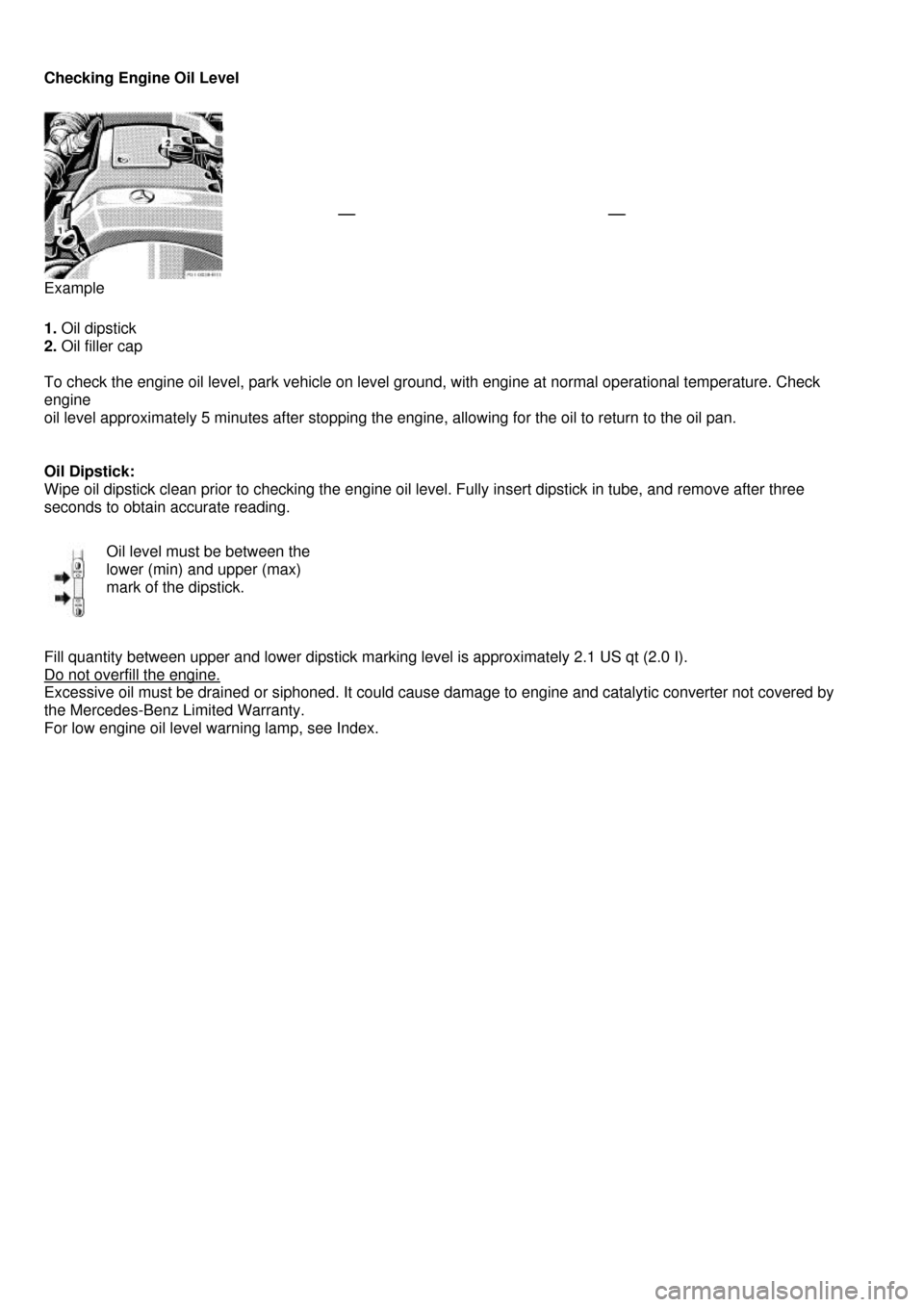
Checking Engine Oil Level
Example
1. Oil dipstick
2. Oil filler cap
To check the engine oil level, park vehicle on level ground, with engine at normal operational temperature. Check
engine
oil level approximately 5 minutes after stopping the engine, allowing for the oil to return to the oil pan.
Oil Dipstick:
Wipe oil dipstick clean prior to checking the engine oil level. Fully insert dipstick in tube, and remove after three
seconds to obtain accurate reading.
Oil level must be between the
lower (min) and upper (max)
mark of the dipstick.
Fill quantity between upper and lower dipstick marking level is approximately 2.1 US qt (2.0 I).
Do not overfill the engine.
Excessive oil must be drained or siphoned. It could cause damage to engine and catalytic converter not covered by
the Mercedes-Benz Limited Warranty.
For low engine oil level warning lamp, see Index.
Page 88 of 130
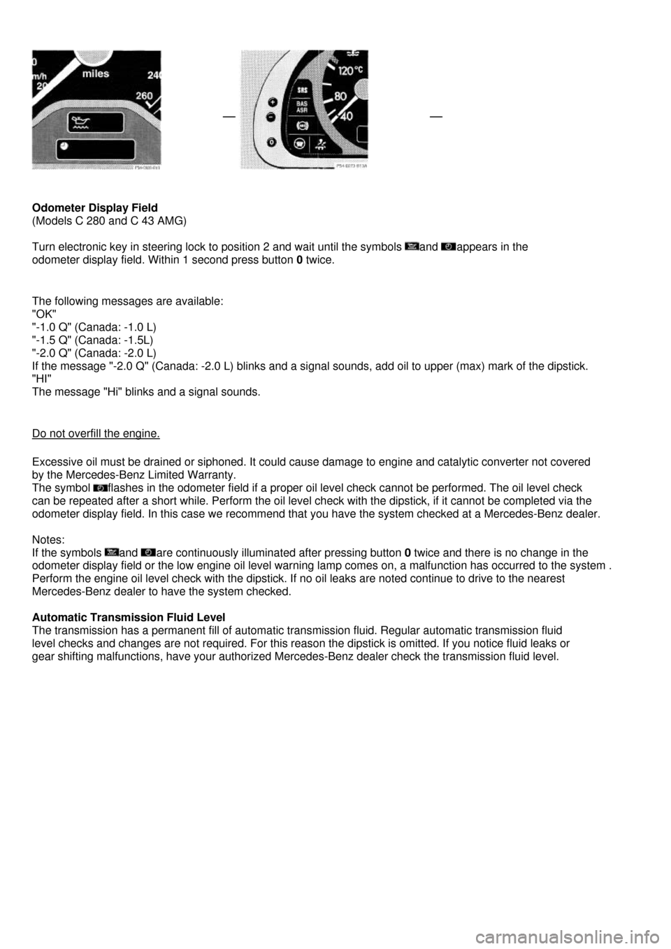
Odometer Display Field
(Models C 280 and C 43 AMG)
Turn electronic key in steering lock to position 2 and wait until the symbols and appears in the
odometer display field. Within 1 second press button 0 twice.
The following messages are available:
"OK"
"-1.0 Q" (Canada: -1.0 L)
"-1.5 Q" (Canada: -1.5L)
"-2.0 Q" (Canada: -2.0 L)
If the message "-2.0 Q" (Canada: -2.0 L) blinks and a signal sounds, add oil to upper (max) mark of the dipstick.
"HI"
The message "Hi" blinks and a signal sounds.
Do not overfill the engine.
Excessive oil must be drained or siphoned. It could cause damage to engine and catalytic converter not covered
by the Mercedes-Benz Limited Warranty.
The symbol flashes in the odometer field if a proper oil level check cannot be performed. The oil level check
can be repeated after a short while. Perform the oil level check with the dipstick, if it cannot be completed via the
odometer display field. In this case we recommend that you have the system checked at a Mercedes-Benz dealer.
Notes:
If the symbols and are continuously illuminated after pressing button 0 twice and there is no change in the
odometer display field or the low engine oil level warning lamp comes on, a malfunction has occurred to the system .
Perform the engine oil level check with the dipstick. If no oil leaks are noted continue to drive to the nearest
Mercedes-Benz dealer to have the system checked.
Automatic Transmission Fluid Level
The transmission has a permanent fill of automatic transmission fluid. Regular automatic transmission fluid
level checks and changes are not required. For this reason the dipstick is omitted. If you notice fluid leaks or
gear shifting malfunctions, have your authorized Mercedes-Benz dealer check the transmission fluid level.
Page 89 of 130

Trunk Lamp
If the trunk is to remain open for a long period of time, the trunk lamp can be switched off by pulling out the plunger
in the switch (arrow). This prevents the vehicle battery from being discharged. When the trunk lid is closed, the switch
will reset and turn on the lamp next time the lid is opened.
Stowing Things in the Vehicle
Warning !
To help avoid personal injury during a collision or sudden maneuver, exercise care when stowing things.
Put luggage or cargo in the trunk if possible. Do not pile luggage or cargo higher than the seat backs.
Do not place anything on the shelf below the rear window.
Page 96 of 130
Exterior Lamps
Headlamp Adjustment
Correct headlamp adjustment is extremely important. Check and readjust headlamps at regular intervals and
when a bulb has been replaced.
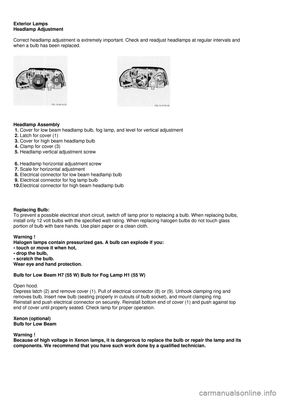
Headlamp Assembly
1. Cover for low beam headlamp bulb, fog lamp, and level for vertical adjustment
2. Latch for cover (1)
3. Cover for high beam headlamp bulb
4. Clamp for cover (3)
5. Headlamp vertical adjustment screw
6. Headlamp horizontal adjustment screw
7. Scale for horizontal adjustment
8. Electrical connector for low beam headlamp bulb
9. Electrical connector for fog lamp bulb
10.Electrical connector for high beam headlamp bulb
Replacing Bulb:
To prevent a possible electrical short circuit, switch off lamp prior to replacing a bulb. When replacing bulbs,
install only 12 volt bulbs with the specified watt rating. When replacing halogen bulbs do not touch glass
portion of bulb with bare hands. Use plain paper or a clean cloth.
Warning !
Halogen lamps contain pressurized gas. A bulb can explode if you:
• touch or move it when hot,
• drop the bulb,
• scratch the bulb.
Wear eye and hand protection.
Bulb for Low Beam H7 (55 W) Bulb for Fog Lamp H1 (55 W)
Open hood.
Depress latch (2) and remove cover (1). Pull of electrical connector (8) or (9). Unhook clamping ring and
removes bulb. Insert new bulb (seating properly in cutouts of bulb socket), and mount clamping ring.
Reinstall and push electrical connector on securely. Reinstall bottom end of cover (1) and push against top
end of cover until properly seated. Check lamp for proper operation.
Xenon (optional)
Bulb for Low Beam
Warning !
Because of high voltage in Xenon lamps, it is dangerous to replace the bulb or repair the lamp and its
components. We recommend that you have such work done by a qualified technician.
Page 97 of 130
Bulb for High Beam H1 (55 W)
Open hood.
Move retaining clamps (4) aside and remove cover (3). Pull off electrical connector (10). Unhook clamping ring
and pull out bulb together with clamping ring. Remove bulb. Insert new bulb (seating properly in cutouts of bulb
socket), mount clamping ring. Reinstall and push electrical connector on securely. Reinstall cover and fasten
with retaining clamp (4).
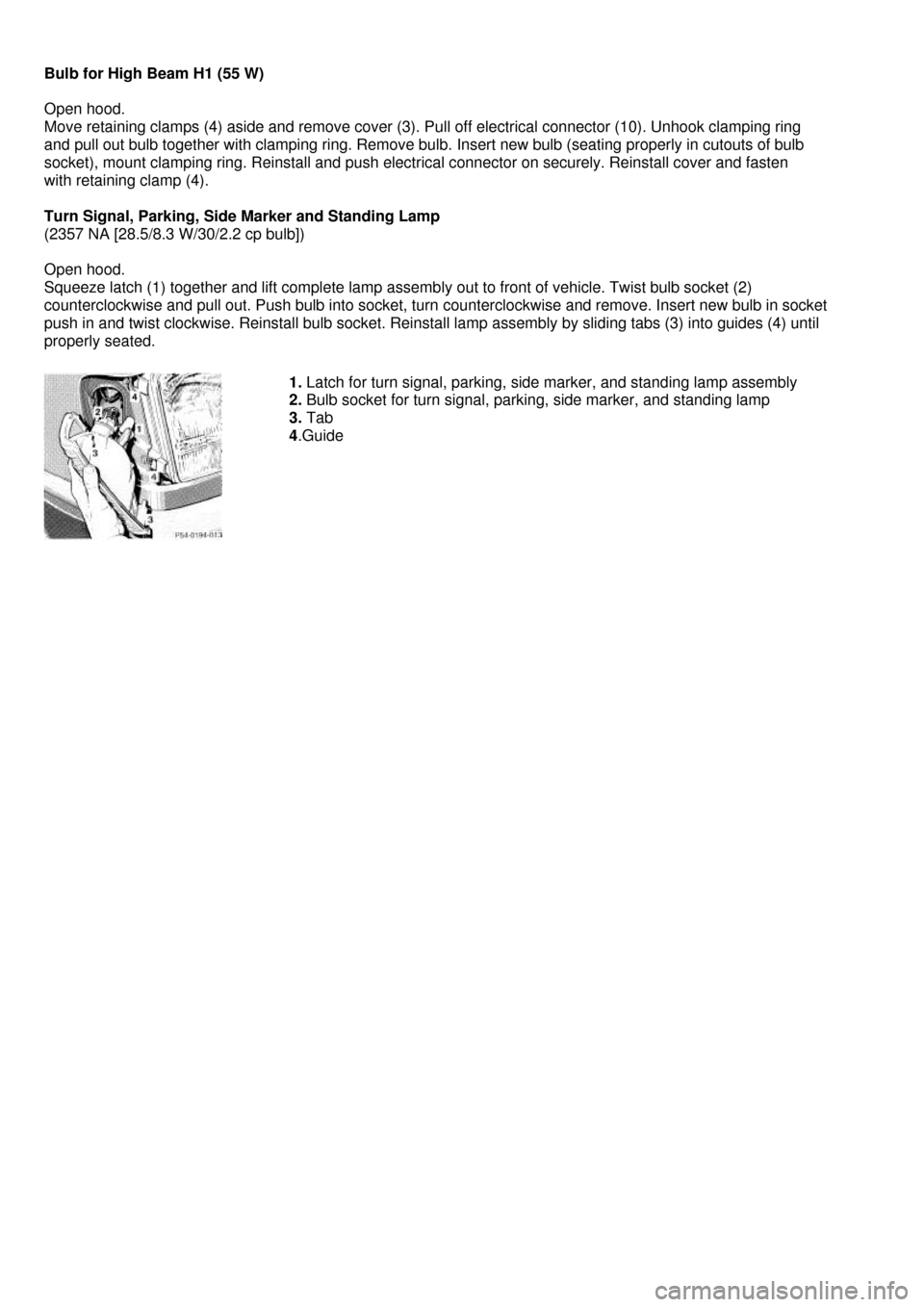
Turn Signal, Parking, Side Marker and Standing Lamp
(2357 NA [28.5/8.3 W/30/2.2 cp bulb])
Open hood.
Squeeze latch (1) together and lift complete lamp assembly out to front of vehicle. Twist bulb socket (2)
counterclockwise and pull out. Push bulb into socket, turn counterclockwise and remove. Insert new bulb in socket
push in and twist clockwise. Reinstall bulb socket. Reinstall lamp assembly by sliding tabs (3) into guides (4) until
properly seated.
1. Latch for turn signal, parking, side marker, and standing lamp assembly
2. Bulb socket for turn signal, parking, side marker, and standing lamp
3. Tab
4.Guide
Page 98 of 130
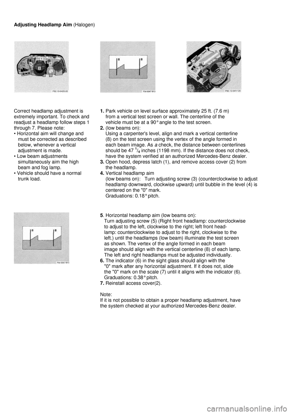
Adjusting Headlamp Aim (Halogen)
Correct headlamp adjustment is
extremely important. To check and
readjust a headlamp follow steps 1
through 7. Please note:
• Horizontal aim will change and
must be corrected as described
below, whenever a vertical
adjustment is made.
• Low beam adjustments
simultaneously aim the high
beam and fog lamp.
• Vehicle should have a normal
trunk load.
1. Park vehicle on level surface approximately 25 ft. (7.6 m)
from a vertical test screen or wall. The centerline of the
vehicle must be at a 90° angle to the test screen.
2. (low beams on):
Using a carpenter's level, align and mark a vertical centerline
(8) on the test screen using the vertex of the angle formed in
each beam image. As a check, the distance between centerlines
should be 47 1/4 inches (1198 mm). If the distance does not check,
have the system verified at an authorized Mercedes-Benz dealer.
3. Open hood, depress latch (1), and remove access cover (2) from
the headlamp.
4. Vertical headlamp aim
(low beams on): Turn adjusting screw (3) (counterclockwise to adjust
headlamp downward, clockwise upward) until bubble in the level (4) is
centered on the "0" mark.
Graduations: 0.18° pitch.
5. Horizontal headlamp aim (low beams on):
Turn adjusting screw (5) (Right front headlamp: counterclockwise
to adjust to the left, clockwise to the right; left front head-
lamp: counterclockwise to adjust to the right, clockwise to the
left.) until the headlamps (low beam) illuminate the test screen
as shown. The vertex of the angle formed in each beam
image should align with the vertical centerline (8) of each lamp.
The left and right headlamps must be adjusted individually.
6. The indicator (6) in the sight glass should align with the
"0" mark after any horizontal adjustment. If it does not, slide
the "0" mark on the scale (7) until it aligns with the indicator (6).
Graduations: 0.38° pitch.
7. Reinstall access cover(2).
Note:
If it is not possible to obtain a proper headlamp adjustment, have
the system checked at your authorized Mercedes-Benz dealer.
Page 99 of 130
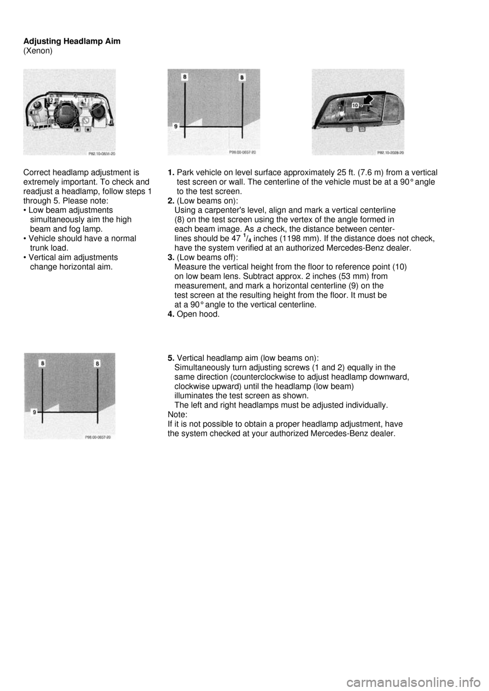
Adjusting Headlamp Aim
(Xenon)
Correct headlamp adjustment is
extremely important. To check and
readjust a headlamp, follow steps 1
through 5. Please note:
• Low beam adjustments
simultaneously aim the high
beam and fog lamp.
• Vehicle should have a normal
trunk load.
• Vertical aim adjustments
change horizontal aim.
1. Park vehicle on level surface approximately 25 ft. (7.6 m) from a vertical
test screen or wall. The centerline of the vehicle must be at a 90° angle
to the test screen.
2. (Low beams on):
Using a carpenter's level, align and mark a vertical centerline
(8) on the test screen using the vertex of the angle formed in
each beam image. As a check, the distance between center-
lines should be 47 1/4 inches (1198 mm). If the distance does not check,
have the system verified at an authorized Mercedes-Benz dealer.
3. (Low beams off):
Measure the vertical height from the floor to reference point (10)
on low beam lens. Subtract approx. 2 inches (53 mm) from
measurement, and mark a horizontal centerline (9) on the
test screen at the resulting height from the floor. It must be
at a 90° angle to the vertical centerline.
4. Open hood.
5. Vertical headlamp aim (low beams on):
Simultaneously turn adjusting screws (1 and 2) equally in the
same direction (counterclockwise to adjust headlamp downward,
clockwise upward) until the headlamp (low beam)
illuminates the test screen as shown.
The left and right headlamps must be adjusted individually.
Note:
If it is not possible to obtain a proper headlamp adjustment, have
the system checked at your authorized Mercedes-Benz dealer.