warning light MERCEDES-BENZ C-CLASS 2002 Owners Manual
[x] Cancel search | Manufacturer: MERCEDES-BENZ, Model Year: 2002, Model line: C-CLASS, Model: MERCEDES-BENZ C-CLASS 2002Pages: 399, PDF Size: 16.95 MB
Page 5 of 399

2
Contents
Multifunction steering wheel, multifunction display ............... 102
Trip and main odometer and sub menu.................................... 106
Audio systems ................................ 108 Radio ............................................ 108
CD player ..................................... 109
Cassette player ........................... 110
Telephone ......................................... 111
Navigation system ........................... 116
Trip computer ................................. 117
Malfunction/warning message memory ....................... 119
Individual settings......................... 121
Setting the audio volume.............. 136
Coolant temperature gauge .......... 137
Flexible service system (FSS) ...... 138
Engine oil level indicator .............. 141
Engine oil consumption ................ 142
Exterior lamp switch ..................... 143
Headlamp mode ............................. 144 Night security illumination ......... 146
Locator lighting.......................... 147
Headlamp cleaning system .......... 147
Combination switch ...................... 148
Hazard warning flasher switch .... 151
Climate control .............................. 152
Automatic climate control............ 160
Front center console storage compartment ventilation .......... 171
Rear passenger compartment adjustable air outlets ............... 172
Operation Audio and telephone ................................... 173
Operating safety ............................ 173
Operating and display elements .. 174
Button and soft key operation ...... 176
Component malfunctions ............. 195
Power windows .............................. 197
Sunshade for panorama sliding/pop-up roof .................. 199
Panorama sliding/pop-up roof .... 200
Interior lighting ............................. 203
Sun visors ....................................... 205
Vanity mirrors................................ 205 Interior............................................. 206
Storage compartments
and armrests ..............................206
Glove box ..................................... 207
Cup holder ...................................... 210
Ashtrays .......................................... 211
Lighter ............................................. 213
Parcel net in front passenger footwell ....................................... 214
Split folding rear seat bench ........ 215
Luggage cover – removal and installation ......................... 217
Loading instructions (vehicle with enlarged cargo area) ........ 218
Cellular telephone ......................... 219
Telephone, general ........................ 220
Garage door opener ....................... 221
DrivingControl and operation of radio transmitters ..................... 226
The first 1 000 miles (1 500 km) ................................. 227
ProCarManuals.com
Page 30 of 399
27
Contents - Operation
Te ch n i c a l
data
Instruments
and controls Operation
DrivingInstrument
cluster display Practical hints Car care Index
Individual settings......................... 121
Setting the audio volume.............. 136
Coolant temperature gauge .......... 137
Flexible service system (FSS) ...... 138
Engine oil level indicator .............. 141
Engine oil consumption ................ 142
Exterior lamp switch ..................... 143
Headlamp mode ............................. 144
Night security illumi
nation.......... 146
Locator lighting .......................... 147
Headlamp cleaning system .......... 147
Combination switch....................... 148
Hazard warning flasher switch ... 151
Climate control ............................... 152
Automatic climate control ............ 160 Front center console storage
compartment ventilation .......... 171
Rear passenger compartment adjustable air outlets ............... 172
Operation Audio and telephone ................................... 173
Operating safety ............................ 173
Operating and display elements .. 174
Button and soft key operation ...... 176
Component malfunctions ............. 195
Power windows .............................. 197
Sunshade for panorama sliding/pop-up roof .................. 199
Panorama sliding/pop-up roof .... 200
Interior lighting ............................. 203
Sun visors ....................................... 205
Vanity mirrors................................ 205
Interior ............................................ 206 Storage compartments
and armrests ..............................206
Glove box ..................................... 207
Cup holder ...................................... 210
Ashtrays .......................................... 211
Lighter ............................................. 213
Parcel net in front passenger footwell ....................................... 214
Split folding rear seat bench ........ 215
Luggage cover – removal and installation ......................... 217
Loading instructions (vehicle with enlarged cargo area) ........ 218
Cellular telephone ......................... 219
Telephone, general ........................ 220
Garage door opener ....................... 221
ProCarManuals.com
Page 261 of 399
258
Driving instructions
Te ch n i c a l
data
Instruments
and controls Operation
DrivingInstrument
cluster display Practical hints Car care Index
Power assistance
Brakes Excessive use of road salt and other snow melting
chemicals spread on roads during the winter months
may cause a build up of moisture or residue to form on
the braking components. This build up or residue could
cause light corrosion of the braking components if the
vehicle is parked with the brakes cold. Apply steady and
even braking pressure when stopping the vehicle to
warm up and dry the brake components.
Important!
Please pay attention to the function of the brake assist
system (BAS), see page 271.
The condition of the parking brake system is checked
each time the vehicle is in the shop for the required
maintenance service.
If the parking brake is released and the brake warning
lamp in the instrument cluster stays on, the brake fluid
level in the reservoir is too low.
Brake pad wear or a leak in the system may be the
reason for low brake fluid in the reservoir.
Have the brake system inspected at an authorized
Mercedes-Benz Center immediately.
Wa r n i n g !
When the engine is not running, the brake and
steering systems are without power assistance.
Under these circumstances, a much greater effort is
necessary to stop or steer the vehicle.Wa r n i n g !
After driving in heavy rain for some time without
applying the brakes or through water deep enough
to wet brake components or salty road conditions,
the first braking action may be somewhat reduced
and increased pedal pressure may be necessary to
obtain expected braking effect. Be sure to maintain
a safe distance from vehicles in front.Resting your foot on the brake pedal will cause
excessive and premature wear of the brake pads.It can also result in the brakes overheating thereby
significantly reducing their effectiveness. It may
not be possible to stop the vehicle in sufficient time
to avoid an accident.
ProCarManuals.com
Page 284 of 399
281
Contents - Instrument cluster display
Te ch n i c a l
data
Instruments
and controls Operation Driving
Instrument
cluster display Practical hints Car care Index
Instrument cluster displayMalfunction and indicator
lamps in the instrument
cluster ......................................... 282
On-board diagnostic system ......... 283 Check engine malfunction
indicator lamp............................. 283
Brake warning lamp .................. 284
Supplemental restraint
system (SRS) indicator lamp .... 285
Fuel reserve warning................. 286
ABS malfunction indicator
lamp.............................................. 287
Electronic stability program
(ESP) — warning lamp ............... 288
Seat belt nonusage warning lamp ............................................288 Malfunction and indicator
lamp in the center console...... 289
AIRBAG OFF indicator lamp .... 289
Malfunction and warning messages in the
multifunction display .............. 290
DISPLAY DEFECTIVE................ 291
BATTERY / ALTERNATOR ....... 292
ANTILOCK BRAKE SYSTEM .... 293
BRAKE ASSIST........................... 293
BRAKE PAD WEAR.................... 294
BRAKE FLUID ............................ 294
PARKING BRAKE ....................... 295
SEAT BELT SYSTEM .................. 295
ELEC. STABIL. PROG.
(Electronic stability program).. 296
COOLANT (coolant level).......... 297 COOLANT
(coolant temperature) ................ 298
ENGINE OIL LEVEL ................... 299
LIGHTING SYSTEM .................... 300
LIGHT SENSOR........................... 302
DOOR............................................ 302
TRUNK OPEN ............................. 303
HOOD ........................................... 303
TELEPHONE – FUNCTION ....... 304
TELE AID ..................................... 304
WASHER FLUID.......................... 305
RESTRAINT SYSTEM ................. 306
KEY............................................... 306
FUEL RESERVE .......................... 307
UNDERVOLTAGE ........................ 307
STEERING WHEEL ADJUST. ..... 308
ProCarManuals.com
Page 291 of 399

288
Malfunction and indicator lamps
Te ch n i c a l
data
Instruments
and controls Operation Driving
Instrument
cluster display Practical hints Car care Index
Electronic stability program (ESP) — warning lamp The yellow ESP warning lamp in the
speedometer dial comes on with the
electronic key in starter switch position 2.
It should go out with engine running.
If the ESP malfunction indicator lamp remains
illuminated with the engine running, a malfunction has
been detected in the system. Pressing the accelerator
pedal will require greater effort. Only partial engine
output will be available.
See electronic stability program (ESP) on page 274 if the
warning lamp lights up or flashes when the vehicle is
moving. Seat belt nonusage warning lamp
With the electronic key in starter switch
position 2, the seat belt nonusage warning
lamp comes on, and a warning sounds for a
short time if the drivers seat belt is not fastened.
After starting the engine, the seat belt nonusage
warning lamp blinks for a brief period to remind the
driver and passengers to fasten seat belts.
ProCarManuals.com
Page 303 of 399
300
Malfunction and warning messages
Te ch n i c a l
data
Instruments
and controls Operation Driving
Instrument
cluster display Practical hints Car care Index
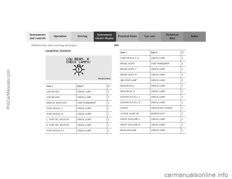
LIGHTING SYSTEM
Line 1 Line 2C*
LOW BEAM,L CHECK LAMP!2
LOW BEAM,R CHECK LAMP!2
DISPLAY DEFECTIVE VISIT WORKSHOP!
1
2
TURN SIGNAL, L CHECK LAMP! 2
TURN SIGNAL, R CHECK LAMP! 2
L. TURN SIG. RFLECTR CHECK LAMP! 2
R. TURN SIG. RFLECTR CHECK LAMP! 2
TURN SIGNAL F, L CHECK LAMP! 2
TURN SIGNAL F, R CHECK LAMP!2
BRAKE LIGHT
2
VISIT WORKSHOP! 2
BRAKE LIGHT, L
3
CHECK LAMP! 2
BRAKE LIGHT, R
3
CHECK LAMP! 2
3RD STOP LAMP
3
CHECK LAMP! 2
HIGH BEAM, L CHECK LAMP!2
HIGH BEAM, R CHECK LAMP!2
LICENSE PLATE L, L CHECK LAMP! 2
LICENSE PLATE L, R CHECK LAMP! 2
LIGHTS SWITCH OFF LIGHTS! 1
AUTOM. LIGHT ON REMOVE KEY!1
FRONT FOGLAMP, L CHECK LAMP! 2
FRONT FOGLAMP, R CHECK LAMP! 2
REAR FOGLAMP CHECK LAMP! 2
Line 1
Line 2C*
ProCarManuals.com
Page 304 of 399
301
Malfunction and warning messages
Te ch n i c a l
data
Instruments
and controls Operation Driving
Instrument
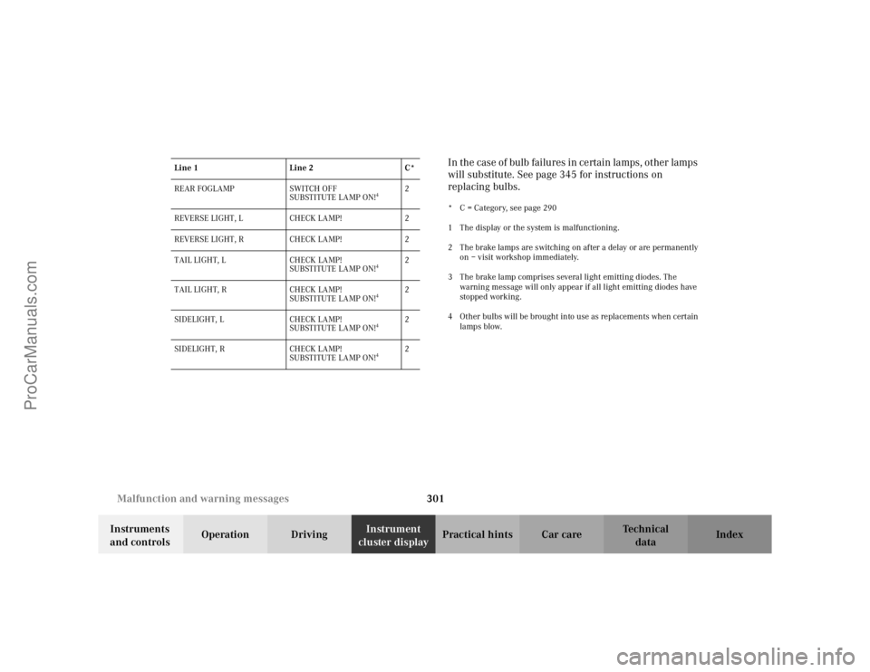
cluster display Practical hints Car care IndexIn the case of bulb failures in certain lamps, other lamps
will substitute. See page 345 for instructions on
replacing bulbs.
* C = Category, see page 290
1 The display or the system is malfunctioning.
2 The brake lamps are switching on after a delay or are permanently
on – visit workshop immediately.
3 The brake lamp comprises several light emitting diodes. The warning message will only appear if all light emitting diodes have
stopped working.
4 Other bulbs will be brought into use as replacements when certain lamps blow.
REAR FOGLAMP SWITCH OFF
SUBSTITUTE LAMP ON!
4
2
REVERSE LIGHT, L CHECK LAMP! 2
REVERSE LIGHT, R CHECK LAMP! 2
TAIL LIGHT, L CHECK LAMP! SUBSTITUTE LAMP ON!
4
2
TAIL LIGHT, R CHECK LAMP! SUBSTITUTE LAMP ON!
4
2
SIDELIGHT, L CHECK LAMP! SUBSTITUTE LAMP ON!
4
2
SIDELIGHT, R CHECK LAMP! SUBSTITUTE LAMP ON!
4
2
Line 1
Line 2C*
ProCarManuals.com
Page 305 of 399

302
Malfunction and warning messages
Te ch n i c a l
data
Instruments
and controls Operation Driving
Instrument
cluster display Practical hints Car care Index
LAMP SENSOR
* C = Category, see page 290The headlamps will be switched on automatically if the
light sensor malfunctions.
The individual setting menu “LIGHTING”, “LIGHT
CIRCUIT HEADLAMP MODE” can be set to “MANUAL”.
See page 128. It will then be possible to switch the
headlamps on and off using the exterior lamp switch.
See page 143 for notes on the exterior lamp switch. DOOR
* C = Category, see page 290.
Line 1 Line 2 C*
LAMP SENSOR VISIT WORKSHOP! 2Line 1
Line 2C*
DOOR OPEN! 1
P54.30-5440-21
ProCarManuals.com
Page 309 of 399
306
Malfunction and warning messages
Te ch n i c a l
data
Instruments
and controls Operation Driving
Instrument
cluster display Practical hints Car care Index
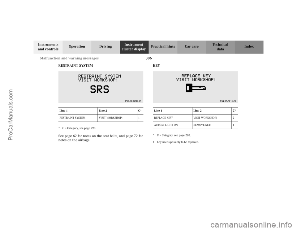
RESTRAINT SYSTEM
* C = Category, see page 290.See page 62 for notes on the seat belts, and page 72 for
notes on the airbags. KEY
* C = Category, see page 290.
1 Key needs possibly to be replaced.
Line 1 Line 2 C*
RESTRAINT SYSTEM VISIT WORKSHOP! 1Line 1
Line 2C*
REPLACE KEY
1
VISIT WORKSHOP! 2
AUTOM. LIGHT ON REMOVE KEY! 1
ProCarManuals.com
Page 342 of 399
339
Jump starting
Te ch n i c a l
data
Instruments
and controls Operation Driving
Instrument
cluster display Practical hints
Car care Index
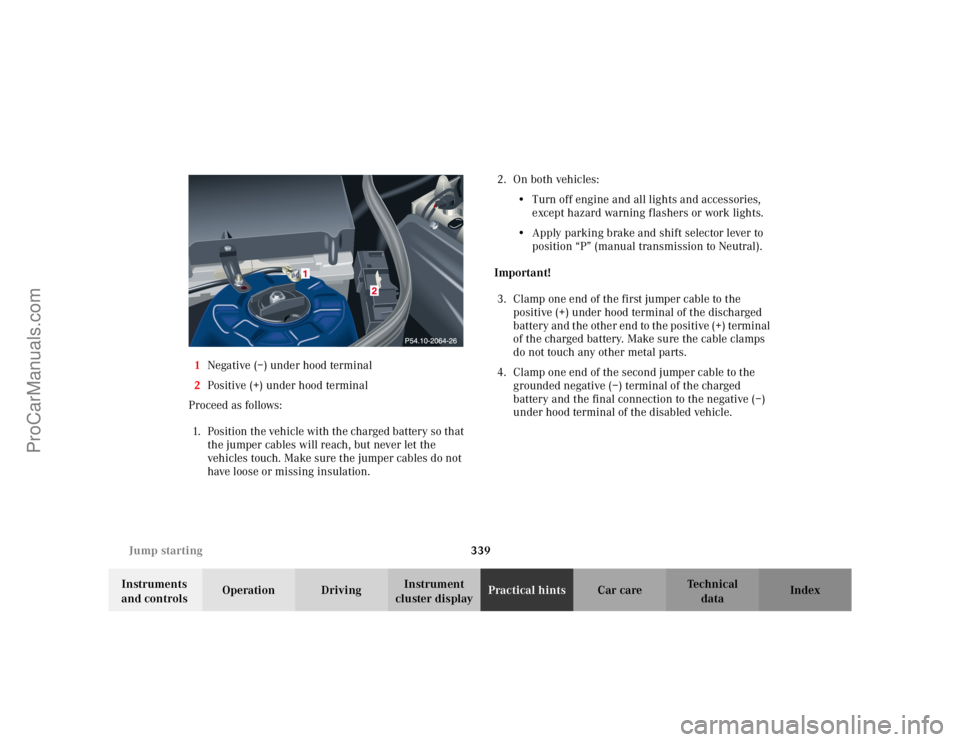
1
Negative (–) under hood terminal
2 Positive (+) under hood terminal
Proceed as follows:
1. Position the vehicle with the charged battery so that the jumper cables will reach, but never let the
vehicles touch. Make sure the jumper cables do not
have loose or missing insulation. 2. On both vehicles:
•Turn off engine and all lights and accessories,
except hazard warning flashers or work lights.
• Apply parking brake and shift selector lever to
position “P” (manual transmission to Neutral).
Important! 3. Clamp one end of the first jumper cable to the positive (+) under hood terminal of the discharged
battery and the other end to the positive (+) terminal
of the charged battery. Make sure the cable clamps
do not touch any other metal parts.
4. Clamp one end of the second jumper cable to the grounded negative (–) terminal of the charged
battery and the final connection to the negative (–)
under hood terminal of the disabled vehicle.
ProCarManuals.com