manual radio set MERCEDES-BENZ C-CLASS CABRIOLET 2016 Owners Manual
[x] Cancel search | Manufacturer: MERCEDES-BENZ, Model Year: 2016, Model line: C-CLASS CABRIOLET, Model: MERCEDES-BENZ C-CLASS CABRIOLET 2016Pages: 377, PDF Size: 6.9 MB
Page 20 of 377
On-board computer
AMG menu .....................................2 37
Assistance graphic menu .............. .231
Assistance menu ........................... 232
Display messages .......................... 240
Displaying a service message ....... .313
DISTRONIC PLUS ........................... 176
Factory settings ............................ .237
G-Meter ......................................... 238
Head-up displa y............................. 223
Important safety notes .................. 220
Instrument cluster menu ............... 236
Light menu ..................................... 235
Media menu ................................... 228
Menu overview .............................. 224
Message memory .......................... 241
Navigation menu ............................ 226
Operating the TV ............................ 230
Operating video DVD ..................... 229
Operation ....................................... 221
RACETIMER ................................... 239
Radio menu ................................... 228
Service menu ................................. 232
Settings menu ............................... 232
Standard display ............................ 224
Telephone menu ............................ 230
Trip menu ...................................... 224
Vehicle menu ................................. 237
Open/close
climate control (air-recirculation
mode) ............................................ 130
Operating instructions
Vehicle equipment ........................... 28
Operating safety
Declaration of conformity ................ 29
Important safety note ...................... 28
Operating system
see On-board computer
Operation
Digital Owner's Manua l.................... 26
Outside temperature display ........... 221
Overhead control panel ...................... 40
Owner's Manual
Overview .......................................... 28 P
Paint code .......................................... 359 Paintwork (cleaning instructions)
... 316
Panic alarm .......................................... 42
Parking
Important safety notes .................. 159
Parking brake ................................ 161
Parking position for the exterior
mirror on the front-passenger
side ................................................ 111
Reversing camera .......................... 193
Switching off the engine ................ 160
see PARKTRONIC
Parking aid
see 360° camera
see Active Parking Assist
see Exterior mirrors
see PARKTRONIC
see Reversing camera
Parking brake
Applying automatically (vehicles
with automatic transmission) ......... 161
Applying automatically (vehicles
with manual transmission) ............. 162
Applying or releasing manually ...... 161
Display message ............................ 244
Electric parking brake .................... 161
Emergency braking ........................ 162
General information ....................... 161
Releasing automaticall y................. 162
Warning lamp ................................. 278
Parking lamps
Display message ............................ 253
Switching on/of f........................... 115
PARKTRONIC
Deactivating/activating ................. 187
Driving system ............................... 185
Function/note s............................. 185
Important safety notes .................. 185
Problem (fault) ............................... 188
Sensor rang e................................. 185
Trailer towing ................................. 185
Warning display ............................. 186
PASSENGER AIR BAG
Display message ............................ 251
Indicator lamps ................................ 43
Problems (malfunctions) ................ 251
Petrol
Flexible fuel vehicles ...................... 363
Pets in the vehicle ............................... 66 Index
17
Page 21 of 377
Phone book
See also Digital Owner's Manual ... 284
Plastic trim (cleaning instruc-
tions) .................................................. 321
Power windows
see Side windows
PRE-SAFE ®
(anticipatory occupant
protection)
Operation ......................................... 57
PRE-SAFE ®
(preventive occupant
safety system)
Display message ............................2 48
PRE-SAFE ®
Brake
Activating/deactivating ................. 233
Display message ............................ 248
Function/notes ................................ 76
Important safety notes .................... 76
Warning lamp ................................. 281
PRE-SAFE ®
PLUS (anticipatory
occupant protection PLUS)
Operation ......................................... 58
Protection against theft
ATA (Anti-Theft Alarm system) ......... 78
Immobiliser ...................................... 78
Interior motion sensor ..................... 79
Tow-away protectio n ........................79
Protection of the environment
General notes .................................. 27
Pulling away
Automatic transmission ................. 135
General notes ................................ 135
Hill start assist ............................... 136
Manual transmission ..................... .135
Trailer ............................................ 136 Q
QR code Mercedes-Benz Guide App ................. 1
Rescue card ..................................... 31
Qualified specialist workshop ........... 30
Quick access for audio and tele-
phone
Changing the station/music
track .............................................. 287 R
RACE START (Mercedes-AMG vehi-
cles) .................................................... 181
RACETIMER (on-board computer) .... 239
Radiator cover ................................... 309
Radio
Selecting a station ......................... 228
Radio mode
See also Digital Owner's Manual ... 284
Radio-based vehicle components
Declaration of conformity ................ 29
Reading lamp ..................................... 119
Rear bench seat
Folding the backrest forwards/
back ............................................... 298
Rear compartment
Setting the air vents ..................... .131
Rear foglamp
Display message ............................ 253
Switching on/off ........................... 115
Rear seat (folding the backrest for-
wards/back) ...................................... 299
Rear window heating
Problem (fault) ............................... 129
Switching on/off ........................... 129
Rear-compartment seat belt sta-
tus indicator ........................................ 47
Rear-view mirror
Anti-dazzle mode (automatic) ....... .111
Dipping (manual )........................... 109
Recuperation display ........................ 225
Reflective safety vest ....................... 323
Refuelling
AdBlue ®
......................................... 156
Fuel gaug e....................................... 35
Important safety notes .................. 153
Notes for Mercedes‑ AMG vehi-
cles ................................................ 362
Refuelling process ......................... 154
see Fuel
Removing
the folding draught stop ................... 98
Replacing bulbs
Dipped-beam headlamp s............... 120
Fitting/removing the cover (front
wheel arch) .................................... 121
Important safety notes .................. 119 18
Index
Page 26 of 377
Blind Spot Assist ............................ 206
Cleaning the trailer tow hitch ......... 320
Coupling up a traile
r...................... 215
Decoupling a trailer ....................... 216
Driving tips .................................... 214
Folding in the ball coupling ............ 215
Folding out the ball coupling .......... 214
Important safety notes .................. 213
Lights display message .................. 253
Parktronic ...................................... 185
Power supply ................................. 216
Problem (fault) ............................... 217
Trailer load s................................... 369
Transfer case ..................................... 153
Transmission
see Automatic transmission
see Manual transmission
Transmission position display ......... 146
Transporting the vehicle .................. 338
Trim pieces (cleaning instruc-
tions) .................................................. 321
Trip computer (on-board com-
puter) .................................................. 225
Trip meter
Calling up ....................................... 224
Resetting (on-board computer) ...... 226
Turn signals
Replacing bulbs (front) ................... 120
Switching on/of f........................... 116
TV
Operating (on-board computer) ..... 230
Two-way radio
Frequencies ................................... 358
Installation ..................................... 358
Transmission output (maximum) .... 358
Type identification plate
see Vehicle identification plate
Tyre changing tool kit ....................... 325
Tyre pressure
Calling up (on-board computer) ..... 348
Display message ............................ 265
Not reached (TIREFIT) .................... 329
Reached (TIREFIT) .......................... 329
Recommended ............................... 345
Tyre pressure loss warning
General notes ................................ 347
Important safety notes .................. 347 Restarting ...................................... 347
Tyre pressure monitor
Checking the tyre pressure elec-
tronically ........................................ 349
Function/note s............................. 348
General notes ................................ 348
Important safety notes .................. 348
Radio type approval for the tyre
pressure monitor ........................... 350
Restarting ...................................... 349
Warning lamp ................................. 282
Warning message .......................... 349
Tyres
Changing a whee l.......................... 350
Checking ........................................ 343
Direction of rotation ...................... 351
Display message ............................ 265
Important safety notes .................. 342
Information on driving .................... 342
MOExtended tyre s......................... 344
Replacing ....................................... 350
Service life ..................................... 343
Snow chains .................................. 345
Storing ........................................... 351
Summer tyres in winter ................. 344
Tyre size (data ).............................. 355
Tyre tread ...................................... 343
Wheel and tyre combinations ........ 355
see Flat tyre U
Unlocking Emergency unlocking ....................... 89
From inside the vehicle (central
unlocking button) ............................. 88
USB devices
Connecting to the Media Inter-
face ............................................... 295
Using the TIREFIT
tyre pressure kit ............................ 328 V
Vanity mirror (in sun visor) .............. 302
Variable SPEEDTRONIC
see SPEEDTRONIC
Vehicle
Correct use ...................................... 31 Index
23
Page 40 of 377
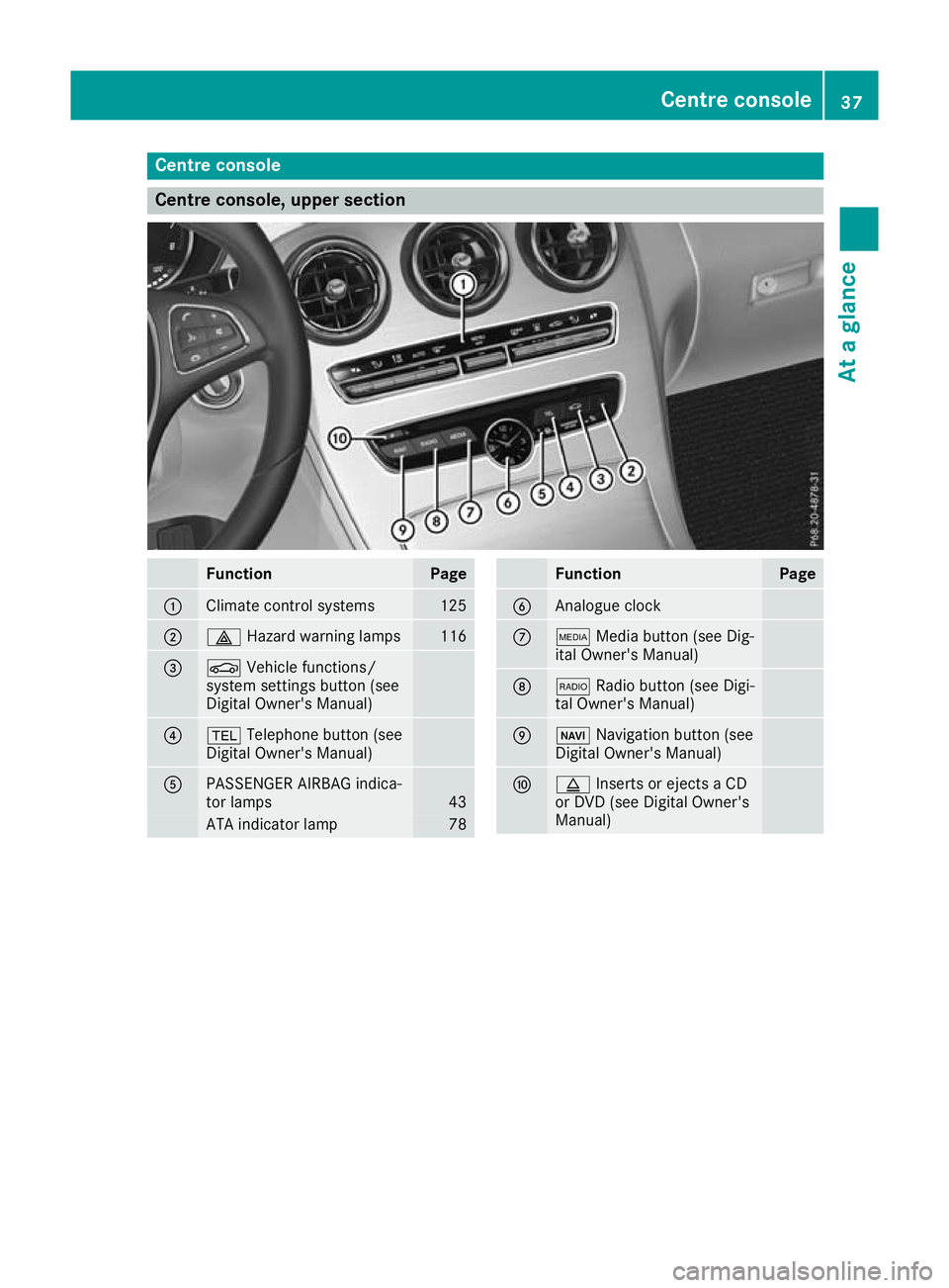
Centre console
Centre console, upper section
Function Page
:
Climate control systems 125
;
£
Hazard warning lamps 116
=
Ø
Vehicle functions/
system settings button (see
Digital Owner's Manual) ?
%
Telephone button (see
Digital Owner's Manual) A
PASSENGER AIRBAG indica-
tor lamps 43
ATA indicator lamp 78 Function Page
B
Analogue clock
C
Õ
Media button (see Dig-
ital Owner's Manual) D
$
Radio button (see Digi-
tal Owner's Manual) E
Ø
Navigation button (see
Digital Owner's Manual) F
þ
Inserts or ejects a CD
or DVD (see Digital Owner's
Manual) Centre console
37At a glance
Page 84 of 377
Key
Important safety notes
United Kingdom only: G
WARNING
When the double locks are activated, the
doors can no longer be opened from the
inside. People in the vehicle can no longer get out, e.g. in hazardous situations. There is a
risk of injury.
Therefore, do not leave any people unsuper-
vised in the vehicle, particularly children, eld-
erly people or people in need of special assis-
tance. Do not activate the double lock when
people are in the vehicle.
If the vehicle has been locked from the outside, the double lock function is activated as stand-
ard. It is then not possible to open the doors
from inside the vehicle. You can deactivate the
double lock function by deactivating the interior
motion sensor (see Digital Owner's Manual).
The doors can then be opened from the inside
after the vehicle has been locked from the out-
side. The anti-theft alarm system is triggered if
the door is opened from the inside. Switch off
the alarm (Y page 78).
All countries: G
WARNING
If children are left unsupervised in the vehicle, they could:
R open doors, thereby endangering other per-
sons or road users
R get out and be struck by oncoming traffic
R operate vehicle equipment and become
trapped, for example
In addition, the children could also set the
vehicle in motion, for example, if they:
R release the parking brake
R shift the automatic transmission out of park
position P or shift manual transmission into
neutral
R start the engine
There is a risk of an accident and injury. When leaving the vehicle, always take the key
with you and lock the vehicle. Never leave
children and animals unattended in the vehi-
cle. Keep the keys out of the reach of children. G
WARNING
If you attach heavy or large objects to the key, the key could be unintentionally turned in the
ignition lock. This could cause the engine to
be switched off. There is a risk of an accident.
Do not attach any heavy or large objects to the
key. Remove any bulky keyrings before insert-
ing the key into the ignition lock.
! Keep the key away from strong magnetic
fields. Otherwise, the remote control function could be affected.
Strong magnetic fields can occur in the vicin-
ity of powerful electrical installations.
Do not keep the key: R with electronic devices, e.g. a mobile phone
or another key
R with metallic objects, e.g. coins or metal foil
R inside metallic objects, e.g. a metal case
This can impair the key's function.
Vehicles with KEYLESS-GO start function: do
not keep the key in the boot. Otherwise, the key
may not be detected, e.g. when starting the
engine using the Start/Stop button.
A check that periodically establishes a radio
connection between the vehicle and the key
determines whether a valid key is in or in the
direct vicinity of the vehicle. This occurs, for
example:
R during engine start
R during driving
R when the external door handles are touched
R during convenience closing Key
81Opening and closing Z
Page 85 of 377

Key functions
:
& Locks the vehicle
; F Opens the boot lid
= % Unlocks the vehicle
X To unlock centrally: press the%button.
If you do not open the vehicle within approx-
imately 40 seconds of unlocking:
R the vehicle locks again
R protection against theft is reactivated
X To lock centrally: press the&button.
The key centrally locks and unlocks the follow-
ing components:
R the doors
R the boot lid
R the glove compartment
R the fuel filler flap
During unlocking, the turn signals flash once.
During locking, they flash three times.
You can also set an audible signal to confirm
that the vehicle has been locked. The audible
signal can be activated and deactivated via the
multimedia system (see Digital Owner's Man-
ual).
Only when all the components have been locked is the visual or audible locking confirmation
issued.
When the locator lighting is activated via the
multimedia system, it lights up when it is dark
after the vehicle is unlocked with the key (see
Digital Owner's Manual).
X To open the boot lid automatically from
outside the vehicle: press and hold theF
button until the boot lid opens. KEYLESS-GO
General notes Note that the engine can be started by any of the
vehicle occupants if there is a key in the vehicle
(Y page 135).
Locking and unlocking centrally You can start, lock or unlock the vehicle using
KEYLESS-GO. To do this, you need to carry the
key with you. You can combine the KEYLESS-GO functions with the functions of a conventional
key. Unlock the vehicle using KEYLESS-GO, for
instance, and lock it using the &button on
the key.
The driver's door and the door at which the han- dle is used must both be closed. The key must beoutside the vehicle. When you lock or unlock the
vehicle with KEYLESS-GO, the distance between the key and the door handle must not be greater
than 1 m.
A check that periodically establishes a radio
connection between the vehicle and the key
determines whether a valid key is in or in the
direct vicinity of the vehicle. This occurs, for
example:
R during engine start
R during driving
R when the external door handles are touched
R during convenience closing X
To unlock the vehicle: touch the inner sur-
face of the door handle.
X To lock the vehicle: touch sensor surface :
or ;. 82
KeyOpening and closing
Page 224 of 377
The segments between the speed of the vehi-
cle in front and the stored speed light up. Rev counter
! Do not drive in the overrevving range. Doing
so will damage the engine.
The red band in the rev counter indicates the
engine's overrevving range.
The fuel supply is interrupted to protect the
engine when the red band is reached. Outside temperature display
You should pay special attention to road condi-
tions when temperatures are around freezing
point.
Bear in mind that the outside temperature dis-
play indicates the measured air temperature
and not the road surface temperature.
The outside temperature display is in the multi-
function display (Y page 222).
Changes in the outside temperature are dis-
played after a short delay. Coolant temperature gauge
G
WARNING
If you open the bonnet while the engine is
overheating or while there is a fire in the
engine compartment, you could come into
contact with hot gases or other leaking ser-
vice products. There is a danger of injury.
Allow an overheating engine to cool down
before opening the bonnet. If there is a fire in the engine compartment, leave the bonnet
closed and notify the fire brigade.
The coolant temperature display is shown in the lower section of the rev counter (Y page 35).
At high outside temperatures and when driving
in mountainous terrain, the coolant temperature
may rise to the end of the scale.
Under normal operating conditions and with the specified coolant level, the display may rise to
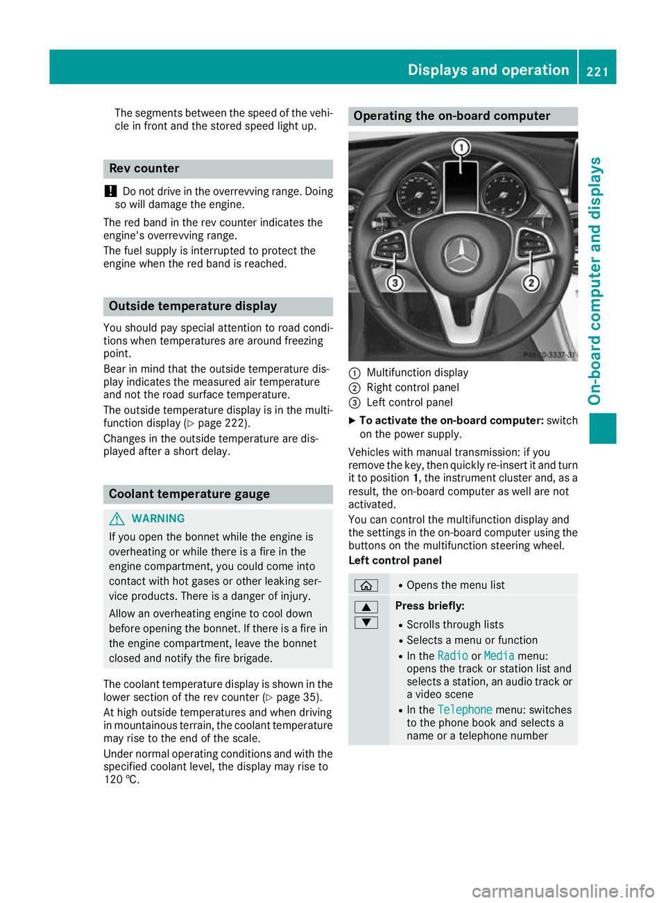
120 †. Operating the on-board computer
:
Multifunction display
; Right control panel
= Left control panel
X To activate the on-board computer: switch
on the power supply.
Vehicles with manual transmission: if you
remove the key, then quickly re-insert it and turn
it to position 1, the instrument cluster and, as a
result, the on-board computer as well are not
activated.
You can control the multifunction display and
the settings in the on-board computer using the buttons on the multifunction steering wheel.
Left control panel ò R
Opens the menu list 9
: Press briefly:
R Scrolls through lists
R Selects a menu or function
R In the Radio Radio orMedia
Media menu:
opens the track or station list and
selects a station, an audio track or a video scene
R In the Telephone Telephone menu: switches
to the phone book and selects a
name or a telephone number Displays and operation
221On-board computer and displays Z
Page 227 of 377

AMG displays on the head-up display
:
Upshift indicator
; RACETIMER lap
= RACETIMER lap time
? Current speed
A Currently selected gear, gearshift options
with manual gearshifting
B Current engine speed
Setting options You can make the following settings on the
head-up display submenu:
R Adjust the position of the head-up display on
the windscreen (Y page 235)
R Adjust the brightness of the displays on the
head-up display (Y page 235)
R Select which information you want to appear
on the head-up display (Y page 234)
Using the Display content
Display content function, you
can, depending on your vehicle's equipment,
choose between four standard displays. The
selected content then appears on the head-
up display.
In Mercedes-AMG vehicles, you can choose
between further AMG displays in addition to
the standard displays, depending on your
vehicle's equipment.
If you select a display with traffic signs, traffic
signs detected by Traffic Sign Assist appear
on the head-up display. Menus and submenus
Menu overview
Press òon the steering wheel to open the
menu list.
Operating the on-board computer (Y page 221).Depending on the vehicle equipment, you can
select the following menus:
R Trip
Trip menu (Y page 224)
R Navi Navi menu (navigation instructions)
(Y page 226)
R Radio
Radio menu (Y page 228)
R Media
Media menu (Y page 228)
R Telephone
Telephone menu (Ypage 230)
R Assistance graphic
Assistance graphic menu (Ypage 231)
R Service
Service menu (Ypage 232)
R Settings
Settings menu (Ypage 232)
R AMG
AMG menu in Mercedes-AMG vehicles
(Y page 237) Trip menu
Standard display X
Press and hold the %button on the steer-
ing wheel until the Trip
Tripmenu with trip
meter :and total distance recorder ;
appears. 224
Menus and submenusOn-board computer and displays
Page 352 of 377

way radios) that may be being operated in or
near the vehicle.
Checking the tyre pressure electroni-
cally X
Make sure that the key is in position 2in the
ignition lock (Y page 133).
X Press òon the steering wheel to call up
the menu list.
X Press 9or: on the steering wheel to
select the Service
Service menu.
X Confirm by pressing aon the steering
wheel.
X Select Tyre pressure Tyre pressure with9 or:.
X Press ato confirm.
The multifunction display shows the current
tyre pressure of each wheel.
If the vehicle was parked for longer than
20 minutes, the following message appears:
Tyre pressures will be displayed Tyre pressures will be displayed
after a few minutes of driving
after a few minutes of driving.
After a teach-in period, the tyre pressure moni-
tor automatically detects new wheels or new
sensors. As long as a clear allocation of the tyre pressure values to the individual wheels is not
possible, the Tyre Tyrepressure
pressure monitor
monitoractive
active
message is shown instead of the tyre pressure
display. The tyre pressures are already being
monitored.
After an emergency spare wheel has been fitted, the system may still display the tyre pressure of
the removed wheel for a few minutes. If this
occurs, note that the value displayed for the
position where the spare wheel is fitted is not
the same as the current tyre pressure of the
emergency spare wheel.
Warning messages of the tyre pressure monitor If the tyre pressure monitor detects a pressure
loss in one or more tyres, a warning message is
shown on the multifunction display. The yellow
tyre pressure warning lamp then lights up:
R If the Please correct tyre pressure
Please correct tyre pressure
message appears on the multifunction dis-
play, the tyre pressure in at least one tyre is
too low. The tyre pressure must be corrected when the opportunity arises.
R If the Check tyre(s)
Check tyre(s) message appears on
the multifunction display, the tyre pressure in at least one tyre has dropped significantly.
The tyres must be checked.
R If the Warning tyre defect
Warning tyre defect message
appears on the multifunction display, the tyre pressure in at least one tyre has dropped sud-
denly. The tyres must be checked.
Observe the instructions and safety notes in the
display messages in the "Tyres" section
(Y page 265).
If the position of the wheels on the vehicle is
changed, the tyre pressures may be displayed in
the wrong positions for a short time. After a few minutes of driving, this is rectified and the tyre
pressures are displayed in the correct positions.
Restarting the tyre pressure monitor When you restart the tyre pressure monitor, all
existing warning messages are deleted and the
warning lamps go out. The monitor uses the cur-
rently set tyre pressures as the reference values
for monitoring. In most cases, the tyre pressure monitor will automatically detect the new refer- ence values after you have changed the tyre
pressure. However, you can also set reference
values manually as described here. The tyre
pressure monitor then monitors the new tyre
pressure values.
X Use the table on the inside of the fuel filler flap
to ensure that the tyre pressure is set cor-
rectly in all four tyres for the current operating
conditions.
Also observe the notes in the section on tyre
pressures (Y page 345).
X Make sure that the key is in position 2in the
ignition lock (Y page 133).
X Press òon the steering wheel to call up
the menu list.
X Press 9or: on the steering wheel to
select the Service
Service menu.
X Confirm by pressing aon the steering
wheel.
X Select Tyre pressure Tyre pressure with9 or:.
X Press ato confirm.
The multifunction display shows the current
tyre pressure of each wheel or the Tyre Tyre
pressures
pressures will
willbe
bedisplayed
displayed after
aftera
a
few minutes of driving
few minutes of driving message.
X Press the :button.
The Use
Use current
current pressures
pressures as
asnew
new ref‐
ref‐
erence values
erence values message is shown on the
multifunction display. Tyre pressure
349Wheels and tyres Z