Check MERCEDES-BENZ C CLASS COUPE 2002 User Guide
[x] Cancel search | Manufacturer: MERCEDES-BENZ, Model Year: 2002, Model line: C CLASS COUPE, Model: MERCEDES-BENZ C CLASS COUPE 2002Pages: 399, PDF Size: 16.59 MB
Page 83 of 399
80
Restraint systems
Te ch n i c a l
data
Instruments
and controls Operation
DrivingInstrument
cluster display Practical hints Car care Index
Safety guidelines for the seat belt, emergency
tensioning retractor and airbag
Wa r n i n g !
If you believe that, even with the use of these
guidelines, it would be safer for your rear seat
occupants to have both rear door mounted side
airbags deactivated, then deactivation can be
accomplished upon your written election to do so at
your authorized Mercedes-Benz Center at an
additional cost. Please contact your local
authorized Mercedes-Benz Center or call our
Customer Assistance Center at 1-800-FOR-
MERCedes (1-800-367-6372) for details.
Wa r n i n g ! • Damaged seat belts or belts that were highly stressed in an accident must be replaced and
their anchoring points must also be checked.
Use only belts installed or supplied by an
authorized Mercedes-Benz Center.• Airbags and “ETR’s” are designed to function on a one-time-only basis. An airbag or
emergency tensioning retractor (ETR) that was
activated must be replaced.• No modifications of any kind may be made to any components or wiring of the “SRS”. This
includes changing or removing any component
or part of the “SRS”, the installation of
additional trim material, badges etc. over the
steering wheel hub, front passenger airbag
cover, door trim panels, or door frame trims,
and installation of additional electrical /
electronic equipment on or near “SRS”
components and wiring. Keep area between
airbags and occupants free from objects (e.g.
packages, purses, umbrellas, etc).
Page 87 of 399
84
Restraint systems
Te ch n i c a l
data
Instruments
and controls Operation
DrivingInstrument
cluster display Practical hints Car care Index
Installation of infant and child restraint systems
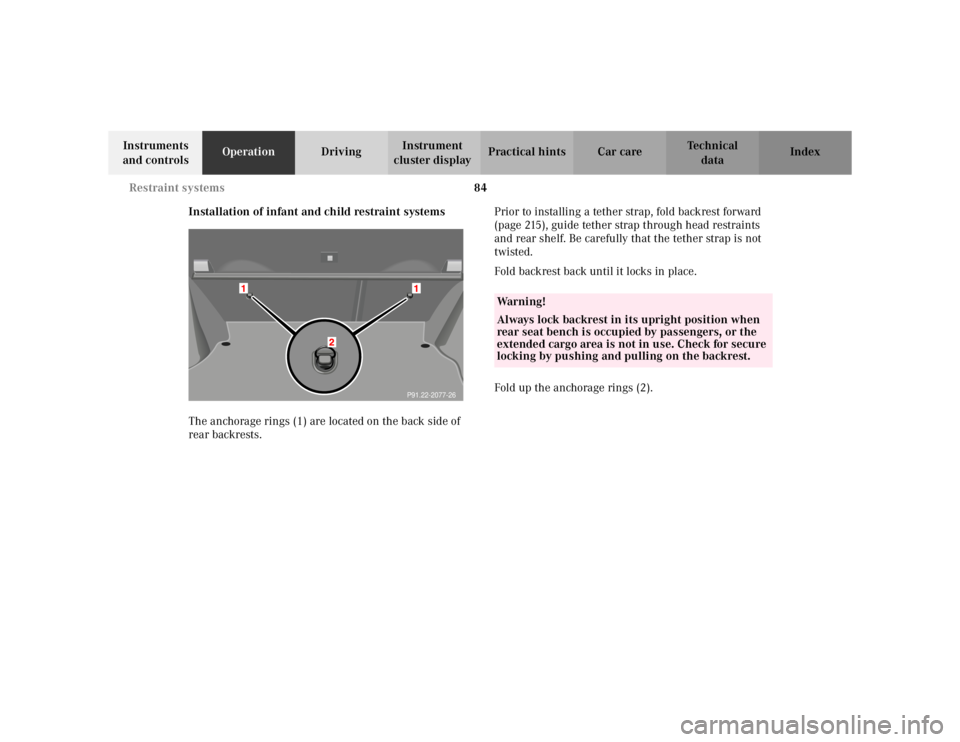
The anchorage rings (1) are located on the back side of
rear backrests. Prior to installing a tether strap, fold backrest forward
(page 215), guide tether strap through head restraints
and rear shelf. Be carefully that the tether strap is not
twisted.
Fold backrest back until it locks in place.
Fold up the anchorage rings (2).
P91.22-2077-26
Wa r n i n g !
Always lock backrest in its upright position when
rear seat bench is occupied by passengers, or the
extended cargo area is not in use. Check for secure
locking by pushing and pulling on the backrest.
Page 93 of 399
90
Rear view mirrors
Te ch n i c a l
data
Instruments
and controls Operation
DrivingInstrument
cluster display Practical hints Car care Index
Exterior rear view mirrors
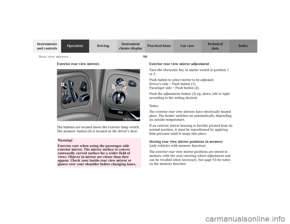
The buttons are located above the exterior lamp switch.
The memory button (4) is located on the driver’s door. Exterior rear view mirror adjustment
Turn the electronic key in starter switch to position 1
or 2.
Push button to select mirror to be adjusted:
Driver’s side – Push button (1).
Passenger side – Push button (2).
Push the adjustment button (3) up, down, left or right
according to the setting desired.
Notes:
The exterior rear view mirrors have electrically heated
glass. The heater switches on automatically, depending
on outside temperature.
If an exterior mirror housing is forcibly pivoted from its
normal position, it must be repositioned by applying
firm pressure until it snaps into place.
Storing rear view mirror positions in memory
(only vehicles with memory function)
The exterior rear view mirror positions are stored in
memory with the seat / steering wheel adjustment and
can be recalled when necessary. See page 93 for notes
on the memory function.
Wa r n i n g !
Exercise care when using the passenger side
exterior mirror. The mirror surface is convex
(outwardly curved surface for a wider field of
view). Objects in mirror are closer than they
appear. Check your inside rear view mirror or
glance over your shoulder before changing lanes.
P88.70-2113-26
Page 98 of 399
95
Memory function
Te ch n i c a l
data
Instruments
and controls Operation
DrivingInstrument
cluster display Practical hints Car care Index
Important!
Prior to operating the vehicle, the driver should check
and adjust if necessary the seat height, seat position
fore and aft, and backrest angle to insure adequate
control, reach and comfort. The head restraint should
also be adjusted for proper height. See also airbag
section for proper seat positioning.
In addition, also adjust the steering wheel to ensure
adequate control, reach, operation and comfort. Both the
inside and outside rear view mirrors should be adjusted
for adequate rearward vision.
Fasten seat belts. Infants and small children should be
seated in a properly secured restraint system that
complies with U.S. Federal Motor Vehicle Safety
Standard 213 and Canadian Motor Vehicle Safety
Standard 213.
All seat, head restraint, steering wheel, and rear view
mirror adjustments as well as fastening of seat belts
should be done before the vehicle is put into motion.
Wa r n i n g !
Children 12 years old and under must never ride in
the front seat, except in a Mercedes-Benz
authorized BabySmart
TM compatible child seat,
which operates with the BabySmart
TM system
installed in the vehicle to deactivate the passenger
side front airbag when it is properly installed.
Otherwise they will be struck by the airbag when it
inflates in a crash. If this happens, serious or fatal
injury can result.
According to accident statistics, children are safer
when properly restrained in the rear seating
positions than in the front seating positions.
Infants and small children must ride in back seats
and be seated in an appropriate infant or child
restraint system, which is properly secured with
the vehicle’s seat belt, fully in accordance with the
child seat manufacturer’s instructions.A child’s risk of serious or fatal injuries is
significantly increased if the child restraints are
not properly secured in the vehicle and the child is
not properly secured in the child restraint.
Page 101 of 399
98
Instrument cluster
Te ch n i c a l
data
Instruments
and controls Operation
DrivingInstrument
cluster display Practical hints Car care Index
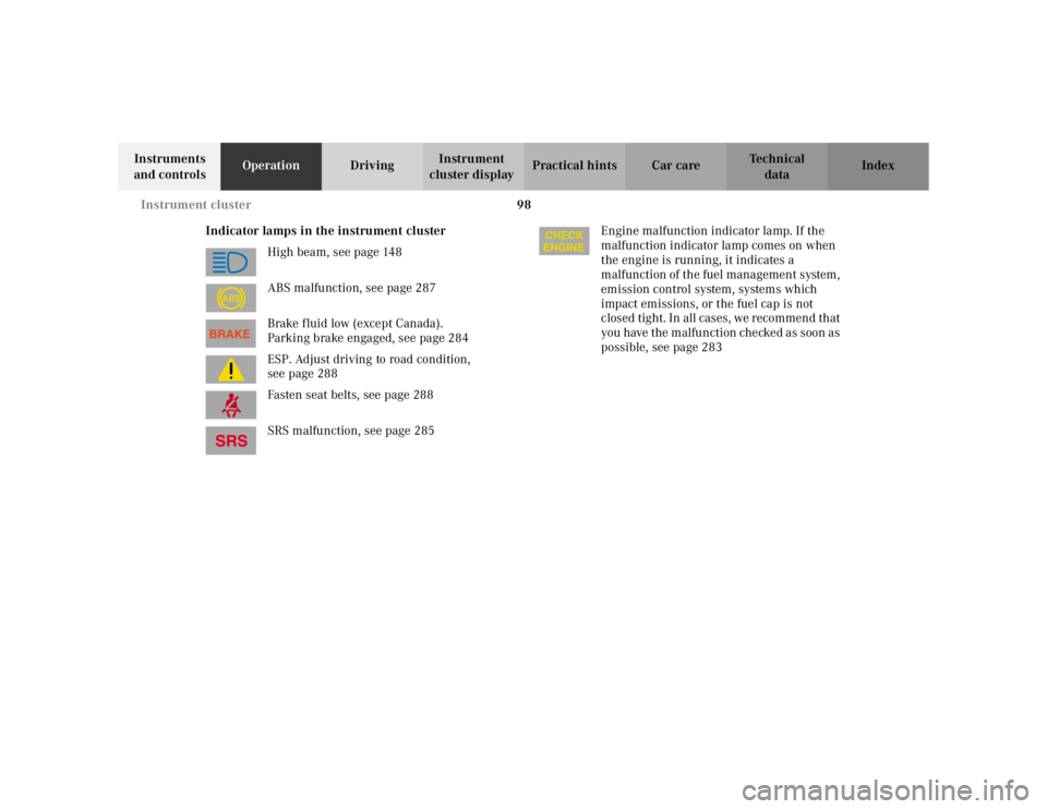
Indicator lamps in the instrument cluster High beam, see page 148
ABS malfunction, see page 287
Brake fluid low (except Canada).
Parking brake engaged, see page 284
ESP. Adjust driving to road condition,
see page 288
Fasten seat belts, see page 288
SRS malfunction, see page 285 Engine malfunction indicator lamp. If the
malfunction indicator lamp comes on when
the engine is running, it indicates a
malfunction of the fuel management system,
emission control system, systems which
impact emissions, or the fuel cap is not
closed tight. In all cases, we recommend that
you have the malfunction checked as soon as
possible, see page 283
ABS
Page 123 of 399

120
Multifunction steering wheel, multifunction display
Te ch n i c a l
data
Instruments
and controls Operation
DrivingInstrument
cluster display Practical hints Car care Index
The message memory will be cleared when the
electronic key is turned in the starter switch to
position 1 or 2. Should any subsequent faults occur,
they will be displayed in the message memory.
Pressing the è or ÿ button displays the next or
previous system. Important!
Malfunction and warning messages are only indicated
for certain systems and displayed to a low level of detail.
The malfunction and warning messages are simply a
reminder with respect to the operation of certain
systems and do not replace the driver’s responsibility to
maintain the vehicle’s operating safety by having all
required maintenance and safety checks performed on
the vehicle and by bringing the vehicle to an authorized
Mercedes-Benz Center to address the malfunction and
warning messages. See page 290, for malfunction and
warning messages.
Page 144 of 399
141
Engine oil level indicator
Te ch n i c a l
data
Instruments
and controls Operation
DrivingInstrument
cluster display Practical hints Car care Index
Engine oil level indicator
To check the engine oil level, park vehicle on level
ground, with engine at normal operational temperature.
Check oil level approximately 5 minutes after turning
off the engine, allowing for the oil to return to the oil
pan.
The message “OBSERVE WAITING PERIOD” will be
displayed if the required waiting period has not been
observed after turning off the engine:
• with engine at operational temperature
approximately 5 minutes. •
with engine not at operational temperature up to
approximately 30 minutes.
The engine oil level check can be repeated after a short
time.
Turn the electronic key in starter switch to position 2.
To call up the trip odometer and main odometer, press
button è or ÿ on the multifunction steering
wheel until the display appears. See page 106.
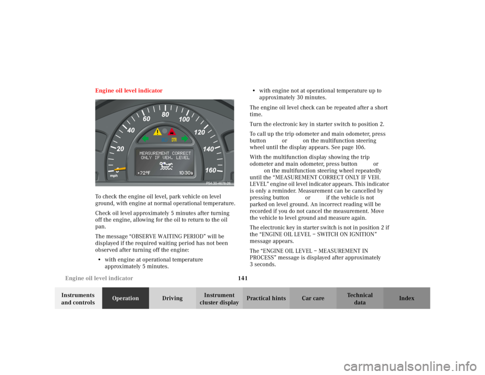
With the multifunction display showing the trip
odometer and main odometer, press button j or
k on the multifunction steering wheel repeatedly
until the “MEASUREMENT CORRECT ONLY IF VEH.
LEVEL” engine oil level indicator appears. This indicator
is only a reminder. Measurement can be cancelled by
pressing button j or k if the vehicle is not
parked on level ground. An incorrect reading will be
recorded if you do not cancel the measurement. Move
the vehicle to level ground and measure again.
The electronic key in starter switch is not in position 2 if
the “ENGINE OIL LEVEL – SWITCH ON IGNITION”
message appears.
The “ENGINE OIL LEVEL – MEASUREMENT IN
PROCESS” message is displayed after approximately
3seconds.
P54.30-4676-26
Page 145 of 399

142
Engine oil level indicator
Te ch n i c a l
data
Instruments
and controls Operation
DrivingInstrument
cluster display Practical hints Car care Index
One of the following messages will subsequently appear
on the indicator:
“ENGINE OIL LEVEL – O.K.”
No oil needs to be added.
“ENGINE OIL LEVEL – ADD 1.0 QUART”
(Canada: 1.0 L)
“ENGINE OIL LEVEL – ADD 1.5 QUART”
(Canada: 1.5 L)
“ENGINE OIL LEVEL – ADD 2.0 QUART”
(Canada: 2.0 L)
See “Adding engine oil level”, on page 318 for
instructions on adding engine oil.
“ENGINE OIL LEVEL – REDUCE OIL LEVEL”
Do not overfill the engine.
Excessive oil must be siphoned or drained off. It could
cause damage to the engine and catalytic converter not
covered by the Mercedes-Benz Limited Warranty. The “MEASURING NOT POSSIBLE” message will be
displayed if a proper oil level check cannot be
performed. The engine oil level check can be repeated
after a short while.
Notes:
See malfunction and warning messages on page 290
and page 299 if an engine oil level indicator appears on
the multifunction display when the engine is running.
The engine oil level cannot be checked while the engine
is running. The “ENGINE OIL LEVEL – NOT WHEN
ENGINE ON” message will appear.
Engine oil consumption
Engine oil consumption checks should only be made
after the break-in period. During the break-in period,
higher oil consumption may be noticed and is normal.
Frequent driving at high engine speeds results in
increased consumption.
Page 153 of 399
150
Combination switch
Te ch n i c a l
data
Instruments
and controls Operation
DrivingInstrument
cluster display Practical hints Car care Index
Blocked windshield wipers
If the windshield wipers become blocked (for example,
due to snow), switch off the wipers.
For safety reasons before removing ice or snow, remove
electronic key from starter switch. Remove blockage.
Activate combination switch again (electronic key in
starter switch position 1).
Emergency operation of windshield wipers
In case of windshield wiper malfunction in switch
positions I or III, turn combination switch to wiper
setting II. Have the system checked at your authorized
Mercedes-Benz Center as soon as possible. Windshield wipers smear
If the windshield wipers smear the windshield, even
during rain, activate the washer system as often as
necessary. The fluid in the washer reservoir should be
mixed in the correct ratio.
See page 320 for instructions on filling up the
windshield washer reservoir.
See page 356 for instructions on replacing wiper blade
inserts.
Windshield and headlamp washer fluid mixing ratio
For temperatures above freezing:
MB Windshield Washer Concentrate “S” and water.
1 part “S” to 100 parts water
(40 ml “S” to 1 gallon water).
For temperature below freezing:
MB Windshield Washer Concentrate “S” and
commercially available premixed windshield washer
solvent / antifreeze
1 part “S” to 100 parts solvent
(40 ml “S” to 1 gallon solvent).
Page 158 of 399

155
Climate control
Te ch n i c a l
data
Instruments
and controls Operation
DrivingInstrument
cluster display Practical hints Car care Index
Climate control
The system is always at operational readiness, except
when manually switched off.
The climate control only operates with the engine
running.
The temperature selector should be left at the desired
temperature setting. The temperature selected is
reached as quickly as possible.
The system will not heat or cool any quicker by setting a
higher or lower temperature.
The desired interior temperature can be selected
separately for the left and right side of the passenger
compartment. Adjust the temperature settings in small
increments.
The climate control removes considerable moisture from
the air during operation in the cooling mode. It is
normal for water to drip on the ground through ducts in
the underbody.
The air conditioning will not engage (no cooling) if the
economy mode S
is selected, see page 159. Notes:
Do not obstruct the air flow by placing objects on the air
flow-through exhaust slots below the rear window.
Also keep the air intake grill in front of the windshield
free of snow and debris.
The storage compartment between the front seats can be
ventilated. See page 171 for notes on ventilating the
storage space under the armrest in the center console.
The air conditioner switches itself off for its own
protection if refrigerant is lost. No cooling will then take
place. Economy mode
S cannot be switched off. Have
the air conditioner checked by a Mercedes-Benz Center
should this happen.
If the vehicle interior has been heated by direct sunlight
and is very hot, ventilate the interior (open door or
windows for a short period) before driving off.
Dust filter
Nearly all dust particles and pollen are filtered out
before outside air enters the passenger compartment
through the air distribution system.