Auto MERCEDES-BENZ C CLASS COUPE 2002 Owner's Manual
[x] Cancel search | Manufacturer: MERCEDES-BENZ, Model Year: 2002, Model line: C CLASS COUPE, Model: MERCEDES-BENZ C CLASS COUPE 2002Pages: 399, PDF Size: 16.59 MB
Page 62 of 399

59
Seats
Te ch n i c a l
data
Instruments
and controls Operation
DrivingInstrument
cluster display Practical hints Car care Index
Note:
When in operation, the seat heater consumes a large
amount of electrical power. It is not advisable to use the
seat heater longer than necessary.
The seat heaters may automatically switch off if too
many power consumers are switched on at the same
time, or if the battery charge is low. When this occurs,
the indicator lamp in the switch will blink (both
indicator lamps blink during
rapid seat heating mode).
The seat heaters will switch on again automatically as
soon as sufficient voltage is available.
If the blinking of the indicator lamps is distracting to
you, the seat heaters can be switched off.
Page 66 of 399

63
Restraint systems
Te ch n i c a l
data
Instruments
and controls Operation
DrivingInstrument
cluster display Practical hints Car care IndexSeat belt nonusage warning system
With the electronic key in starter switch position 2, a
warning sounds for a short time if the driver’s seat belt
is not fastened.
Automatic comfort-fit seat belt:
An automatic comfort-fit feature for driver and front
passenger seat belt is activated when the electronic key
in the starter switch is turned to position 1 or 2.
The retraction force of the inertia reel is reduced,
increasing the level of seat belt comfort.
Note:
For cleaning and care of the seat belts see page 365.
Wa r n i n g !
Never ride in a moving vehicle with the backrest
reclined. Sitting in an excessively reclined position
can be dangerous. You could slide under the seat
belt in a collision. If you slide under it, the belt
would apply force at the abdomen or neck. That
could cause serious or even fatal injuries. The
backrest and seat belt provide the best restraint
when the wearer is in an upright position and the
belt is properly positioned on the body.
Page 72 of 399

69
Restraint systems
Te ch n i c a l
data
Instruments
and controls Operation
DrivingInstrument
cluster display Practical hints Car care Index
BabySmart
TM airbag deactivation system
Special BabySmart
TM compatible child seats, designed
for use with the Mercedes-Benz system and available at
any authorized Mercedes-Benz Center are required for
use with the BabySmart
TM airbag deactivation system.
With the special child seat properly installed, the
passenger front airbag will not deploy.
The ü indicator lamp located in the center console
will be illuminated, except with electronic key removed
or in starter switch position 0. The system does not
deactivate the door mounted side impact airbag.
Self-test BabySmart
TM without special child seat
installed
After turning electronic key in starter switch to
position 1 or 2, the ü indicator lamp located in the
center console comes on for approximately 6 seconds
and then extinguishes.
If the indicator lamp should not come on or is
continuously lit, the system is not functioning. You must
see an authorized Mercedes-Benz Center before seating
any child on the front passenger seat. See page 289 for
notes on the ü indicator lamp.
BabySmart
TM is a trademark of Siemens Automotive Corp.
Wa r n i n g !
The BabySmart
TM airbag deactivation system will
ONLY work with a special child seat designed to
operate with it. It will not work with child seats
which are not BabySmart
TM compatible.
Never place anything between seat cushion and
child seat (e.g. pillow), since it reduces the
effectiveness of the deactivation system. The
bottom of the child seat must make full contact
with the passenger seat cushion. An incorrectly
mounted child seat could cause injuries to the
child in case of an accident instead of protecting
the child.Follow the manufacturer’s instructions for
installation of special child seats.The passenger front airbag will not deploy only if
the ü indicator lamp remains illuminated.Please be sure to check the indicator every time
you use the special system child seat. Should the
light go out while the restraint is installed, please
check installation. If the light remains out, do not
use the BabySmart
TM restraint to transport children
on the front passenger seat until the system has
been repaired.
Page 82 of 399

79
Restraint systems
Te ch n i c a l
data
Instruments
and controls Operation
DrivingInstrument
cluster display Practical hints Car care Index
Wa r n i n g !
Accident research shows that the safest place for
children in an automobile is in the rear seat.
Should you choose to place a child 12 years old or
under in the front passenger seat of your vehicle,
you must properly use a BabySmart
TM child
restraint which will turn off the passenger side
front airbag. BabySmart
TM will not, however, turn
off the vehicle’s side impact airbag.
It should be noted that with respect to both front
and rear side impact airbags there is a possibility
for a side airbag related injury if occupants,
especially children, are not properly seated or
restrained when next to a side airbag which needs
to deploy rapidly in a side impact in order to do its
job.
Wa r n i n g !
To help avoid the possibility of injury, please follow
these guidelines: (1) occupants, especially
children, should never place their bodies or lean
their heads in the area of the door or rear quarter
trim panels where the side airbag inflates. This
could result in serious injuries or death should the
side airbag be activated; (2) always sit upright,
properly use the seat belts and use an
appropriately sized infant or child restraint system
for all children 12 years old or under; and (3)
always wear seat belts properly.
Page 92 of 399

89
Rear view mirrors
Te ch n i c a l
data
Instruments
and controls Operation
DrivingInstrument
cluster display Practical hints Car care Index
Rear view mirrors
Inside rear view mirror
Manually adjust the mirror.
Inside rear view mirror, automatic antiglare
With the electronic key in starter switch position 2, the
mirror reflection brightness responds to changes in
light sensitivity.
With the gear selector lever in position “R”, or with the
interior light switched on, the mirror brightness does
not respond to changes in light sensitivity.
Note:
The automatic antiglare function does not react, if
incoming light is not aimed directly at sensors in the
mirror.
Wa r n i n g !
In the case of an accident liquid electrolyte may
escape the mirror housing when the mirror glass
breaks.Electrolyte has an irritating effect. Do not allow the
liquid come into contact with eyes, skin, clothing,
or respiratory system. In cases it does, immediately
flush affected area with water, and seek medical
help if necessary.
Page 93 of 399

90
Rear view mirrors
Te ch n i c a l
data
Instruments
and controls Operation
DrivingInstrument
cluster display Practical hints Car care Index
Exterior rear view mirrors
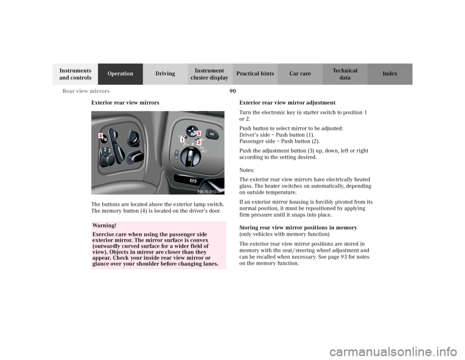
The buttons are located above the exterior lamp switch.
The memory button (4) is located on the driver’s door. Exterior rear view mirror adjustment
Turn the electronic key in starter switch to position 1
or 2.
Push button to select mirror to be adjusted:
Driver’s side – Push button (1).
Passenger side – Push button (2).
Push the adjustment button (3) up, down, left or right
according to the setting desired.
Notes:
The exterior rear view mirrors have electrically heated
glass. The heater switches on automatically, depending
on outside temperature.
If an exterior mirror housing is forcibly pivoted from its
normal position, it must be repositioned by applying
firm pressure until it snaps into place.
Storing rear view mirror positions in memory
(only vehicles with memory function)
The exterior rear view mirror positions are stored in
memory with the seat / steering wheel adjustment and
can be recalled when necessary. See page 93 for notes
on the memory function.
Wa r n i n g !
Exercise care when using the passenger side
exterior mirror. The mirror surface is convex
(outwardly curved surface for a wider field of
view). Objects in mirror are closer than they
appear. Check your inside rear view mirror or
glance over your shoulder before changing lanes.
P88.70-2113-26
Page 95 of 399

92
Rear view mirrors
Te ch n i c a l
data
Instruments
and controls Operation
DrivingInstrument
cluster display Practical hints Car care Index
Driver’s side exterior rear view mirror,
antiglare mode
With the electronic key in starter switch position 2, the
mirror reflection brightness responds to changes in
light sensitivity.
With the gear selector lever in position “R”, or with the
interior light switched on, the mirror brightness does
not respond to changes in light sensitivity.
Note:
The automatic antiglare function does not react, if
incoming light is not aimed directly at sensors in the
inside rear view mirror. Important!
Electrolyte drops coming into contact with the vehicle
paint finish can only be completely removed while in
their liquid state, by applying plenty of water.
Wa r n i n g !
In the case of an accident liquid electrolyte may
escape the mirror housing when the mirror glass
breaks.Electrolyte has an irritating effect. Do not allow the
liquid come into contact with eyes, skin, clothing,
or respiratory system. In cases it does, immediately
flush affected area with water, and seek medical
help if necessary.
Page 102 of 399

99
Instrument cluster
Te ch n i c a l
data
Instruments
and controls Operation
DrivingInstrument
cluster display Practical hints Car care Index
Activating instrument cluster display
The instrument cluster is activated by:
• Opening the door
1.
• Pressing button (1) on the instrument cluster
1.
• Turning the electronic key in starter switch to
position 1 or 2.
• Switching on the exterior lamps.
Instrument cluster illumination
The instrument cluster illumination is dimmed or
brightened automatically to suit daylight lighting
conditions.
The instrument cluster illumination will also be
adjusted when the vehicle’s exterior lamps are switched
on.
1 The instrument cluster is activated for approximately 30 seconds.
Display illumination, changing basic settings for driving
at dusk or in darkness:
Rotate adjusting knob (1) clockwise – instrument lamp
intensity increases.
Rotate adjusting knob (1) counterclockwise –
instrument lamp intensity decreases.
Note:
It is not possible to select a basic brightness setting in
daylight – the intensity is adjusted automatically.
Page 121 of 399

118
Multifunction steering wheel, multifunction display
Te ch n i c a l
data
Instruments
and controls Operation
DrivingInstrument
cluster display Practical hints Car care Index
To reset the short “AFTER START” (1) or long
“AFTER RESET” distance memory (2):
Call up the relevant display (1 or 2) using the j or
k button and press the reset knob on the instrument
cluster, see page 96, until the values are reset to “0”. Note:
The “AFTER START” trip odometer reading is
automatically reset after four hours of electronic key not
being in starter switch position 1 or 2.
Page 128 of 399

125
Multifunction steering wheel, multifunction display
Te ch n i c a l
data
Instruments
and controls Operation
DrivingInstrument
cluster display Practical hints Car care Index
1
Preliminary display of the individual settings
2 “SETTINGS” – the individual setting menu
“INSTRUMENT CLUSTER” can be called up in this
options menu.
Pressing button æ orç on the multifunction
steering wheel controls the selection marker.
3 “SET TIME HOURS:”
1
4“SET TIME MINUTES”
1
5“12/24 O‘CLOCK” – the unit set is displayed in the
instrument cluster display
6 “TEMP. INDICATOR” – the unit set is displayed in
the outside temperature display, in the instrument
cluster and in the automatic air conditioner display.
7 “DISPLAY VALUES IN” – the unit set is displayed in
the multifunction display (except speedometer).
8 “TEXT” – sets the language used in the
multifunction display1 Only vehicles without COMAND.
Vehicles with COMAND, see separate operator’s manual.
9“SELECT DISPLAY” – The selection “SPEED DISP.”
respectively “OUTSIDE TEMPERATURE” is
permanently displayed in the multifunction display.
“SPEED DISP.” can be used to display, for instance,
the present speed in km/h if the setting menu (7)
“DISPLAY VALUES IN” is set to indicate km.
10 See page 127 for instructions on returning the
individual setting menu “INSTRUMENT CLUSTER”
to the factory setting.
11 Acknowledgment.
Note:
Vehicles with COMAND:
For setting clock and speedometer units, see separate
COMAND operator’s manual.