MERCEDES-BENZ C-CLASS COUPE 2011 Owners Manual
Manufacturer: MERCEDES-BENZ, Model Year: 2011, Model line: C-CLASS COUPE, Model: MERCEDES-BENZ C-CLASS COUPE 2011Pages: 373, PDF Size: 8.17 MB
Page 291 of 373
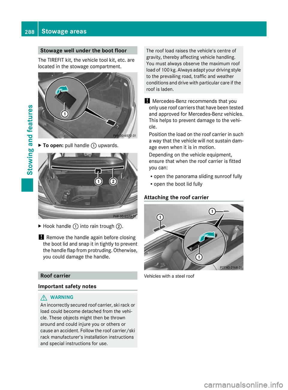
Stowage well under the boot floor
The TIREFIT kit, the vehicle tool kit, etc. are
located in the stowage compartment. X
To open: pull handle :upwards. X
Hook handle :into rain trough ;.
! Remove the handle again before closing
the boot lid and snap it in tightly to prevent
the handle flap from protruding. Otherwise,
you could damage the handle. Roof carrier
Important safety notes G
WARNING
An incorrectly secured roof carrier, ski rack or
load could become detached from the vehi-
cle. These objects might then be thrown
around and could injure you or others or
cause an accident. Follow the roof carrier/ski
rack manufacturer's installation instructions
and special instructions for use. The roof load raises the vehicle's centre of
gravity, thereby affecting vehicle handling.
You must always observe the maximum roof
load of 100 kg. Always adapt your driving style
to the prevailing road, traffic and weather
conditions and drive with particular care if the
roof is laden.
! Mercedes-Benz recommends that you
only use roof carriers that have been tested
and approved for Mercedes-Benz vehicles.
This helps to prevent damage to the vehi-
cle.
Position the load on the roof carrier in such
a way that the vehicle will not sustain dam-
age even when it is in motion.
Depending on the vehicle equipment,
ensure that when the roof carrier is fitted
you can:
R open the panorama sliding sunroof fully
R open the boot lid fully
Attaching the roof carrier Vehicles with a steel roof288
Stowage areasStowing and features
Page 292 of 373
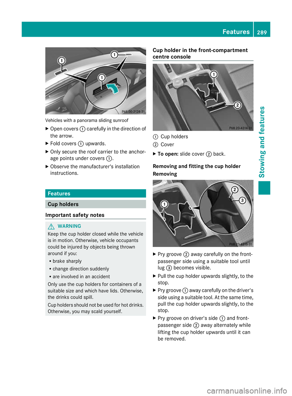
Vehicles with a panorama sliding sunroof
X
Open covers :carefully in the direction of
the arrow.
X Fold covers :upwards.
X Only secure the roof carrier to the anchor-
age points under covers :.
X Observe the manufacturer's installation
instructions. Features
Cup holders
Important safety notes G
WARNING
Keep the cup holder closed while the vehicle
is in motion. Otherwise, vehicle occupants
could be injured by objects being thrown
around if you:
R brake sharply
R change direction suddenly
R are involved in an accident
Only use the cup holders for containers of a
suitable size and which have lids. Otherwise,
the drinks could spill.
Cup holders should not be used for hot drinks.
Otherwise, you may scald yourself. Cup holder in the front-compartment
centre console
:
Cup holders
; Cover
X To open: slide cover ;back.
Removing and fitting the cup holder
Removing X
Pry groove ;away carefully on the front-
passenger side using a suitable tool until
lug =becomes visible.
X Pull the cup holder upwards slightly, to the
stop.
X Pry groove :away carefully on the driver's
side using a suitable tool. At the same time,
pull the cup holder upwards slightly, to the
stop.
X Pry groove on driver's side :and front-
passenger side ;away alternately while
lifting the cup holder upwards until it can
be removed. Features
289Stowing and features Z
Page 293 of 373
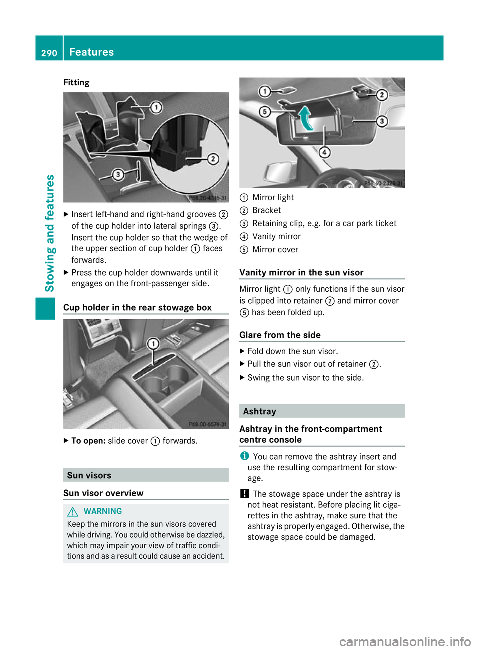
Fitting
X
Inser tleft-hand and right-hand grooves ;
of the cup holder into lateral springs =.
Inser tthe cup holder so that the wedge of
the upper section of cup holder :faces
forwards.
X Press the cup holder downwards until it
engages on the front-passenger side.
Cup holder in the rear stowage box X
To open: slide cover :forwards. Sun visors
Sun visor overview G
WARNING
Keep the mirrors in the sun visors covered
while driving. You could otherwise be dazzled,
which may impair your view of traffic condi-
tions and as a result could cause an accident. :
Mirror light
; Bracket
= Retaining clip, e.g. for a car park ticket
? Vanity mirror
A Mirror cover
Vanity mirror in the sun visor Mirror light
:only functions if the sun visor
is clipped into retainer ;and mirror cover
A has been folded up.
Glare from the side X
Fold down the sun visor.
X Pull the sun visor out of retainer ;.
X Swing the sun visor to the side. Ashtray
Ashtray in the front-compartment
centre console i
You can remove the ashtray insert and
use the resulting compartmentf or stow-
age.
! The stowage space under the ashtray is
not heat resistant .Before placing lit ciga-
rettes in the ashtray, make sure that the
ashtray is properly engaged. Otherwise, the
stowage space could be damaged. 290
FeaturesStowing and features
Page 294 of 373
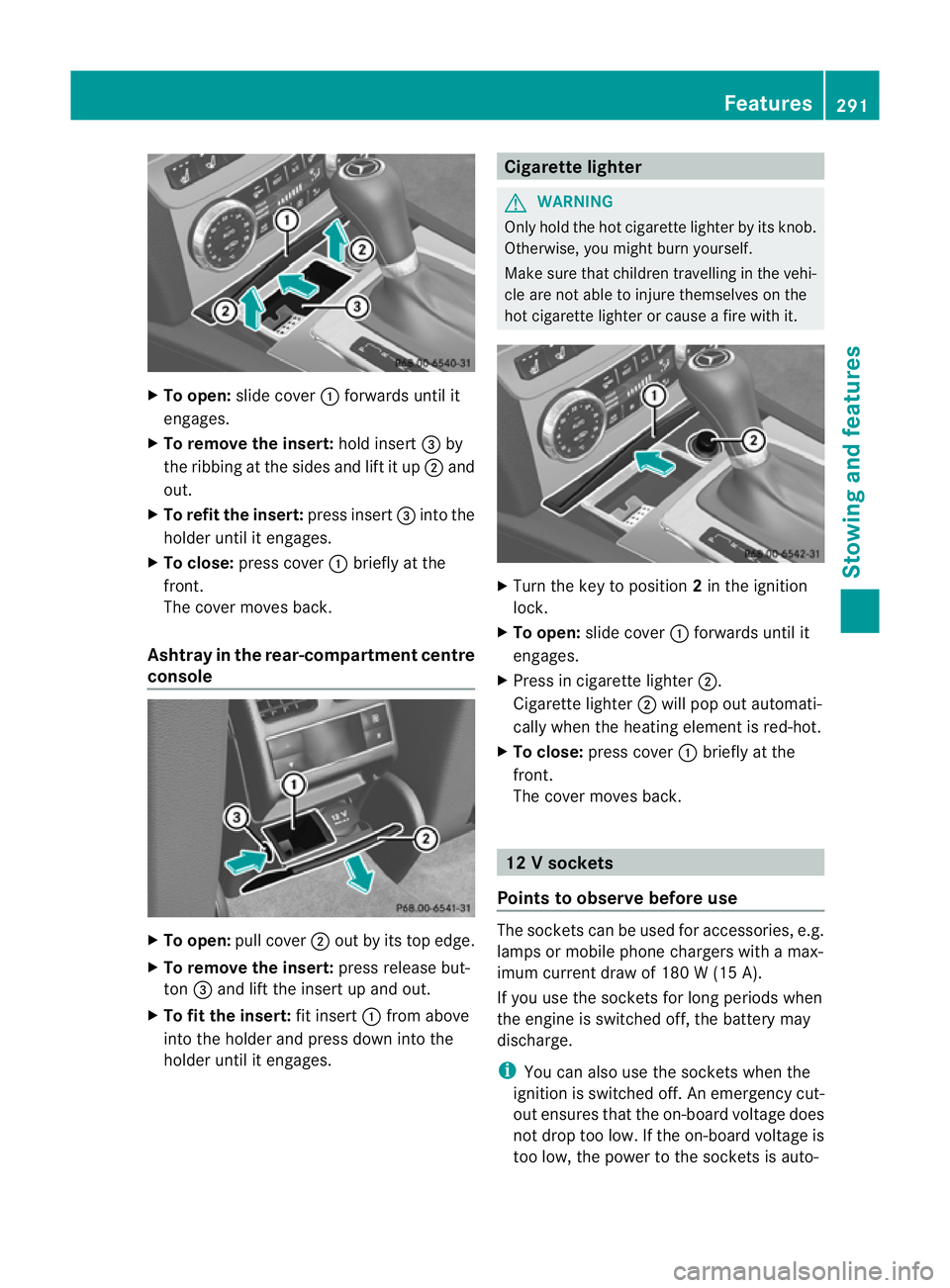
X
To open: slide cover :forwards until it
engages.
X To remove the insert: hold insert=by
the ribbing at the sides and lift it up ;and
out.
X To refi tthe insert: press insert =into the
holder until it engages.
X To close: press cover :briefly at the
front.
The cover moves back.
Ashtray in the rear-compartment centre
console X
To open: pull cover ;out by its top edge.
X To remove the insert: press release but-
ton =and lift the insert up and out.
X To fit the insert: fit insert:from above
into the holder and press dow ninto the
holde runtil it engages. Cigarette lighter
G
WARNING
Only hold the hot cigarette lighte rby its knob.
Otherwise, you might burn yourself.
Make sure that children travelling in the vehi-
cle are no table to injure themselves on the
hot cigarette lighter or cause a fire with it. X
Turn the key to position 2in the ignition
lock.
X To open: slide cover :forwards until it
engages.
X Press in cigarette lighter ;.
Cigarette lighter ;will pop out automati-
cally when the heating element is red-hot.
X To close: press cover :briefly at the
front.
The cover moves back. 12
Vsockets
Points to observe before use The sockets can be used for accessories, e.g.
lamps or mobile phone chargers with a max-
imum current draw of 180 W (15 A).
If you use the sockets for long periods when
the engine is switched off
,the battery may
discharge.
i You can also use the sockets when the
ignition is switched off. An emergency cut-
out ensures that the on-board voltage does
not drop too low. If the on-board voltage is
too low, the power to the sockets is auto- Features
291Stowing and features Z
Page 295 of 373
matically cut. This ensures that there is suf-
ficient power to start the engine.
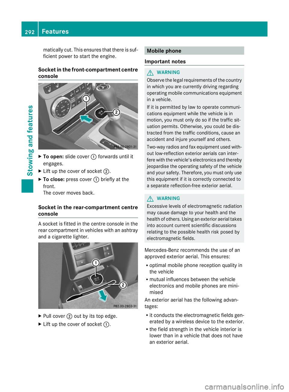
Socket in the front-compartment centre
console X
To open: slide cover :forwards until it
engages.
X Lift up the cover of socket ;.
X To close: press cover :briefly at the
front.
The cover moves back.
Socket in the rear-compartment centre
console As
ocket is fitted in the centre console in the
rear compartment in vehicles with an ashtray
and a cigarette lighter. X
Pull cover ;out by its top edge.
X Lift up the cover of socket :. Mobile phone
Important notes G
WARNING
Observe the legal requirements of the country
in which you are currently driving regarding
operating mobile communications equipment
in a vehicle.
If it is permitted by law to operate communi-
cations equipment while the vehicle is in
motion, you must only do so if the traffic sit-
uation permits. Otherwise, you could be dis-
tracted from the traffic conditions, cause an
accident and injure yourself and others.
Two-way radios and fax equipment used with-
out low-reflection exterior aerials can inter-
fere with the vehicle's electronics and thereby
jeopardise the operating safety of the vehicle
and your safety. Therefore, you must only use
this equipment if it is correctly connected to
a separate reflection-free exterior aerial. G
WARNING
Excessive levels of electromagnetic radiation
may cause damage to your health and the
health of others. Using an exterior aerial takes
into account current scientific discussions
relating to the possible health risk posed by
electromagnetic fields.
Mercedes-Benz recommends the use of an
approved exterior aerial. This ensures:
R optimal mobile phone reception quality in
the vehicle
R mutual influences between the vehicle
electronics and mobile phones are mini-
mised
An exterior aerial has the following advan-
tages:
R it conducts the electromagnetic fields gen-
erated by a wireless device to the exterior.
R the field strength in the vehicle interior is
lower than in a vehicle that does not have
an exterior aerial. 292
FeaturesStowing and features
Page 296 of 373
i
There are various mobile phone brackets
that may be fitted to your vehicle; in some
cases, these are country-specific.
i Even if your vehicle is equppied with con-
venience telephony, you can connect a
Bluetooth ®
-capable mobile phone with
Audio 20 or COMAND Online via the Blue-
tooth ®
interface.
More information on suitable mobile phones,
mobile phone brackets and on connecting
Bluetooth ®
-capable mobile phones with
Audio 20 or COMAND Online can be obtained:
R at your Mercedes-Benz Service Centre
R on the Internet at http://www.mercedes-
benz.com/connect
i The functions and services available when
you use the phone depend on your mobile
phone model and service provider.
Inserting the mobile phone X
Open the telephone compartment
(Y page 285).
X Place the mobile phone bracket into the
pre-installed bracket (see the separate
mobile phone bracket installation instruc-
tions).
X Insert the mobile phone into the mobile
phone bracket (see the separate mobile
phone bracket installation instructions).
If the mobile phone is inserted in the mobile
phone bracket, you can speak to the person
you are calling using the hands-free system.
i On some mobile phone brackets, first you
have to connect the mobile phone via Blue-
tooth ®
with a mobile phone bracket (see
the separate operating instructions for the
mobile phone bracket).
On these mobile phone brackets, the
mobile phone does not have to be inserted
into the bracket for you to be able to use
the telephone functions. In this case, the
charging function and aerial function are
not available. Operating the mobile phone You can operate the telephone using the
6
and~ buttons on the luxury multi-
function steering wheel. You can operate
other mobile phone functions via the on-
board computer (Y page 219).
When you take the key out of the ignition lock,
the mobile phone stays on but you can no
longer use the hands-free system.
If you are making a call and you would like to
take the key out of the ignition lock, first
remove the mobile phone from the bracket.
Otherwise, the call will be ended.
i When a mobile phone bracket is used that
is connected to the mobile phone via Blue-
tooth ®
: if you want to continue a call in
"Private mode", you have to perform the
necessary steps on the mobile phone (see
the separate mobile phone operating
instructions).
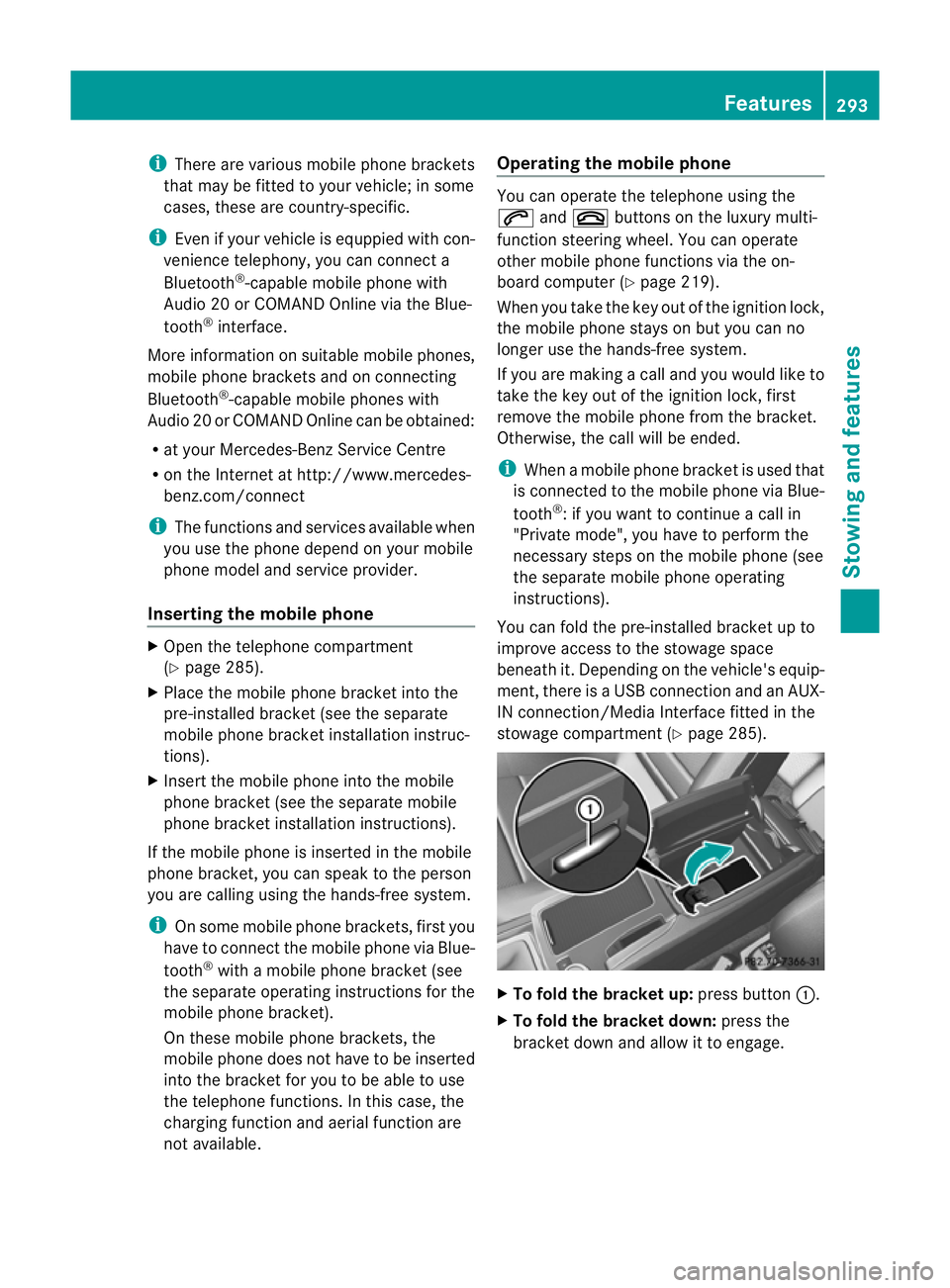
You can fold the pre-installed bracket up to
improve access to the stowage space
beneath it. Depending on the vehicle's equip-
ment,t here is aUSB connection and an AUX-
IN connection/Media Interface fitted in the
stowage compartment (Y page 285). X
To fold the bracket up: press button:.
X To fold the bracket down: press the
bracket dow nand allow it to engage. Features
293Stowing an d features Z
Page 297 of 373
Garage door opener
Important safety notes The HomeLink
®
garage door opener integra-
ted in the rear-view mirror allows you to oper-
ate up to three different door and gate sys-
tems.
i The garage door opener is only available
for certain countries. Observe the legal
requirements in each country.
The HomeLink ®
garage door opener is
compatible with most Europea ngarage and
gate opener drives. More informatio non
HomeLink ®
and/o rcompatible products is
available from:
R any Mercedes-Benz Service Centre
R the HomeLink ®
hotline
(0) 08000 466 354 65 (free of charge) or
+49 (0) 6838 907 277 (charges apply)
R on the Internet at:
http://www.homelink.com
Programming the integrated garage
door opener in the rear-view mirror Programming
G
WARNING
Only press the transmitter button on the inte-
grated garage door opener if there are no per-
sons or objects present within the sweep of
the garage door. Persons could otherwise be
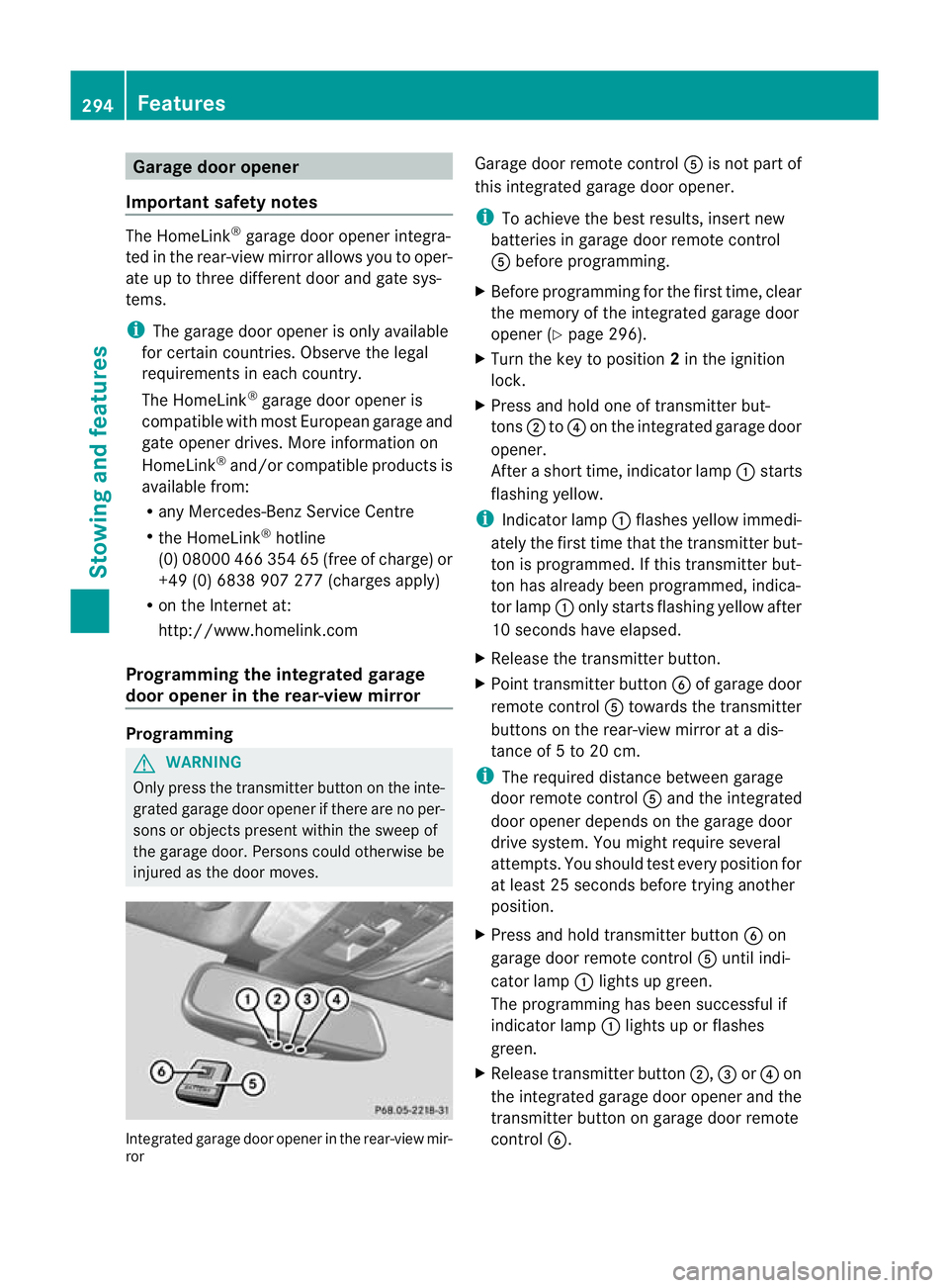
injured as the door moves. Integrated garage door opener in the rear-view mir-
ror Garage door remote control
Ais not part of
this integrated garage door opener.
i To achieve the best results, insert new
batteries in garage door remote control
A before programming.
X Before programming for the first time, clear
the memory of the integrated garage door
opener (Y page 296).
X Turn the key to position 2in the ignition
lock.
X Press and hold one of transmitter but-
tons ;to? on the integrated garage door
opener.
After a short time, indicator lamp :starts
flashing yellow.
i Indicator lamp :flashes yellow immedi-
ately the first time that the transmitter but-
ton is programmed. If this transmitter but-
ton has already been programmed, indica-
tor lamp :only starts flashing yellow after
10 seconds have elapsed.
X Release the transmitter button.
X Point transmitter button Bof garage door
remote control Atowards the transmitter
buttons on the rear-view mirror at a dis-
tance of 5 to 20 cm.
i The required distance between garage
door remote control Aand the integrated
door opener depends on the garage door
drive system. You might require several
attempts. You should test every position for
at least 25 seconds before trying another
position.
X Press and hold transmitter button Bon
garage door remote control Auntil indi-
cator lamp :lights up green.
The programming has been successful if
indicator lamp :lights up or flashes
green.
X Release transmitter button ;,=or? on
the integrated garage door opener and the
transmitter button on garage door remote
control B. 294
FeaturesStowing and features
Page 298 of 373
If indicator lamp
:lights up red:
X Repeat the programming procedure for the
transmitter buttons. When doing so, vary
the distance betwee nthe garage door drive
remote control and the rear-view mirror.
i If the indicator lamp flashes green after
successful programming, the garage door
system is using a rolling code. After pro-
gramming, you must synchronise the
garage door opener integrated in the rear-
view mirror with the receiver of the garage
door system.
Synchronising the rolling code
Your vehicle must be within reach of the
garage or gate opener drive. Make sure that
neither your vehicle nor any persons/objects
are present within the sweep of the door or
gate.
Observe the safety notes when performing
the rolling code synchronisation.
X Turn the key to position 2in the ignition
lock.
X Press the programming button of the door
or gate drive (see the door or gate drive
operating instructions, e.g. under "Pro-
gramming of additional remote controls").
i Usually, you now have 30 seconds to ini-
tiate the next step.
X Press the previously programmed button of
the integrated HomeLink ®
garage door
opener repeatedly until the door starts to
move.
The rolling code synchronisation is then
complete.
Problems when programming
If you have problems when programming the
integrated garage door opener, please note
the following:
R check the transmitter frequency of garage
door remote control A(this can usually be
found on the rear of the remote control).
R change the batteries in garage door remote
control A.This increases the likelihood that garage door remote control
Awill
send a strong and precise signal to the
integrated remote control in the rear-view
mirror.
R when programming, hold garage door
remote control Aat different distances
and angles from the transmitter button that
you are programming. Try various angles at
a distance of between 5 and 30 cm or the
same angle but varying distances.
R if there is another remote control for the
same garage door drive, perform the pro-
gramming steps again using this remote
control. Before performing these steps,
make sure that new batteries have been
fitted in the garage door drive remote con-
trol.
R note that some remote controls transmit
only for a limited period (the indicator lamp
on the remote control goes out). Press the
button on the remote control again before
transmission ends.
R align the aerial cable of the garage door
opener unit. This can improve signal recep-
tion/transmission.
Opening or closing the garage door Once programmed, the integrated garage
door opener will assume the function of the
garage door system's remote control. Please
also read the operating instructions for the
garage door system.
X
Turn the key to position 2in the ignition
lock.
X Press overhead control panel transmitter
button ;,=or? that you have pro-
grammed to operate the garage door.
Garage door system with a fixed code: indi-
cator lamp :lights up green.
Garage door system with a rolling code:
indicator lamp :flashes green.
i The transmitter will transmit a signal for
as long as the transmitter button is
pressed. The transmission is halted after a
maximum of 10 seconds, and indicator Features
295Stowing and features Z
Page 299 of 373
lamp
:flashes yellow. Press the transmit-
ter button again, if necessary.
Clearing the memory of the integrated
garage door opener in the rear-view mir-
ror X
Turn the key to position 2in the ignition
lock.
X Press transmitter buttons ;and ?.
The indicator lamp lights up yellow.
X Press and hold transmitter buttons ;
and ?until the indicator lamp turns green.
i Make sure that you clear the memory of
the integrated garage door opener before
selling the vehicle. 296
FeaturesStowing and features
Page 300 of 373
Frequencies for the garage door opener
The radio type approval number and the frequency range for the garage door opener can be
found on the Internet at: http://www.mercedes-benz.de/betriebsanleitung. Floormat on the driver's side
G
WARNING
Make sure that there is sufficien tclearance
around the pedals when floormats are used,
and that the floormats are properly secured.
The floormats must be correctly secured at all
times using retainers and press-studs.
Before you drive off, chec kthe floormats and
secure if necessary. Afloormat which is not
properly secured can slip and, thereby, inter-
fere with the movemen tofthe pedals.
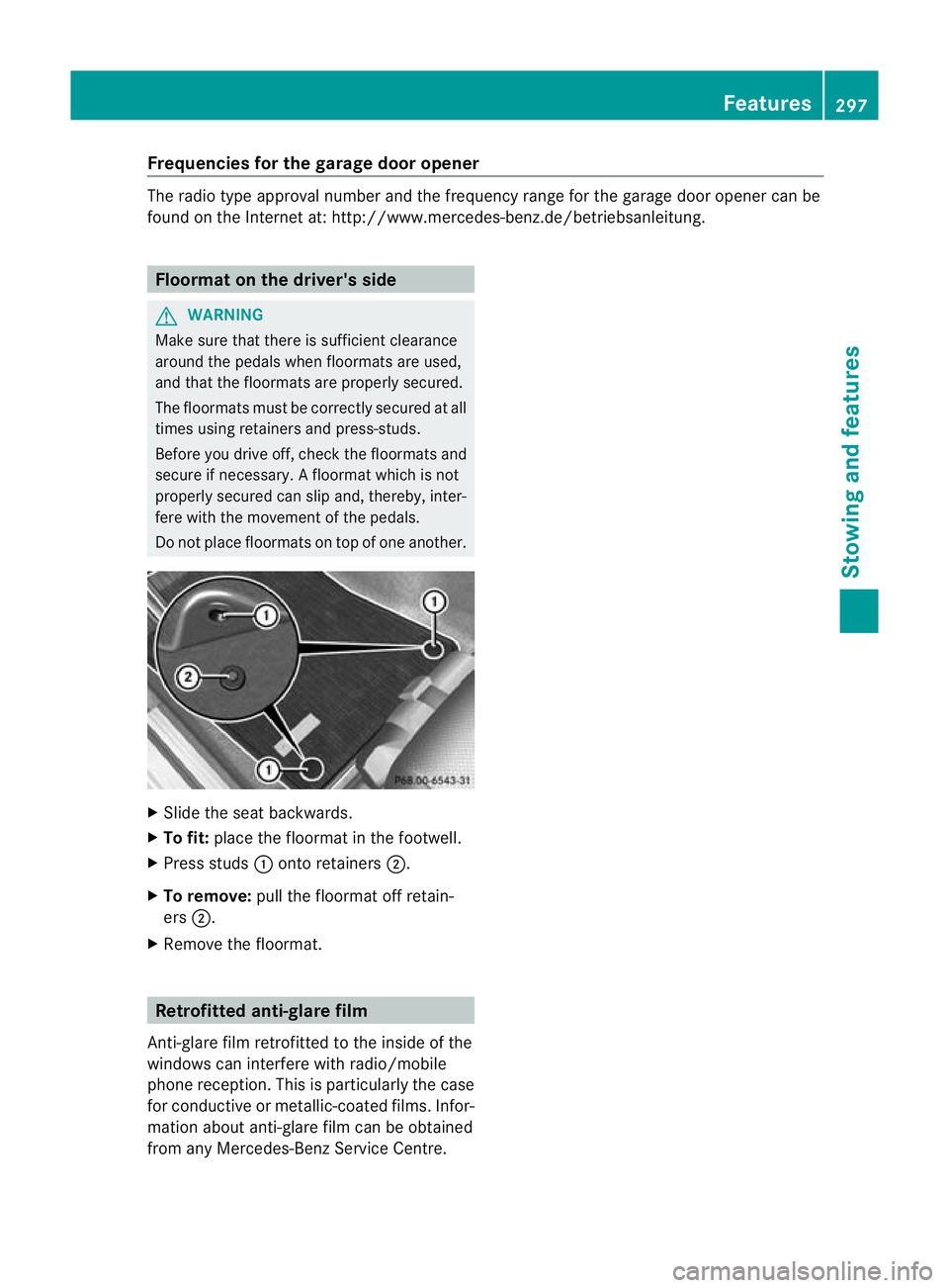
Do not place floormats on top of one another. X
Slide the seat backwards.
X To fit: place the floormat in the footwell.
X Press studs :onto retainers ;.
X To remove: pull the floormat off retain-
ers ;.
X Remove the floormat. Retrofitted anti-glare film
Anti-glare film retrofitted to the inside of the
windows can interfere with radio/mobile
phone reception. This is particularly the case
for conductive or metallic-coated films. Infor-
mation about anti-glare film can be obtained
from any Mercedes-Benz Service Centre. Features
297Stowing and features Z