boot MERCEDES-BENZ C-CLASS COUPE 2018 Owner's Guide
[x] Cancel search | Manufacturer: MERCEDES-BENZ, Model Year: 2018, Model line: C-CLASS COUPE, Model: MERCEDES-BENZ C-CLASS COUPE 2018Pages: 593, PDF Size: 10.86 MB
Page 433 of 593
0007
Vehicles with automatic transmission
must not be tow- star ted. 0007
Vehicles with automatic transmission must
not be tow- star ted.
Ve hicles with manual transmission 0007
Obser vethe no tes on towing away
( 0013 page 426). 0007
If necessar y,allow the engine and exhaust
sy stem tocool down. 0007
Switch the ignition on. 0007
Enga gesecond gear. 0007
Release the electric parking brake. 0007
Tow- start theve hicle while the clutch pedal
is fully depressed. 0007
Slowly release the clutch pedal. 0007
Immediately shift toneutral if the engine
st arts. 0007
Pull over and stop theve hicle, paying atten‐
tion toroad and traf fic conditions. 0007
Remo vetheto w bar. 0007
Remo vetheto wing eye. 0007
Have theve hicle checked at a qualified spe‐
cialist workshop. Electrical fuses
Note
s on electrical fuses 000A
WARNING Risk of accident and inju ry
due to ov erloaded lines
If yo u manipulate or bridge a faulty fuse or if
yo ure place it with a fuse with a higher
amperage, the electric line could be overloa‐
ded.
This could result in a fire. 0007
Alw aysre place faulty fuses with speci‐
fi ed new fuses conta iningthe cor rect
amperage. 000E
NO
TEDama gedue toincor rect fuses Electrical components or sy
stems may be
damaged byincor rect fuses, or their func‐
tionality may be significant lyimpaired. 0007
Only use fuses that ha vebeen appr oved
by Mercedes-Benz and which ha vethe
cor rect fuse rating. Blown fuses mu
stbe replaced with fuses of the
same rating, which you can recognise bythe col‐
our and fuse rating. The fuse ratings and fu rther
information tobe obser ved are lis ted in the fuse
assignment diagram.
Fu se assignment diag ram: onthe fuse box in
th e boot (0013 page 432).
000E NO
TEDama geor malfunctions caused
by moisture Moisture may cause dama
getothe electrical
sy stem or cause it tomalfunction. 0007
When the fuse box is open, make sure
th at no moisture can enter the fuse
box. 0007
When closing the fuse box, make sure
th at the seal of the lid is positioned cor‐
re ctly on the fuse box. 430
Breakdown assis tance
Page 434 of 593
If
th e newly inser ted fuse also blo ws, ha vethe
cause traced and rectified at a qualified special‐
ist workshop.
Ensure thefo llowing before replacing a fuse:
R The vehicle is secured against rolling away
R All electrical consumers are switched off
R The ignition is switched off
The electrical fuses are located in various fuse
bo xes:
R Fuse box in the engine compartment on the
driver's side (0013 page 431)
R Fuse box on the driver's side of the cockpit
(0013 page 432)
R Fuse box in the front passenger foot we ll
(0013 page 432)
R Fuse box in the boot on theright-hand side
of theve hicle when vie wed in the direction of
tr av el (0013 page 432) Opening and closing
the fuse box in the
engine compa rtment Re
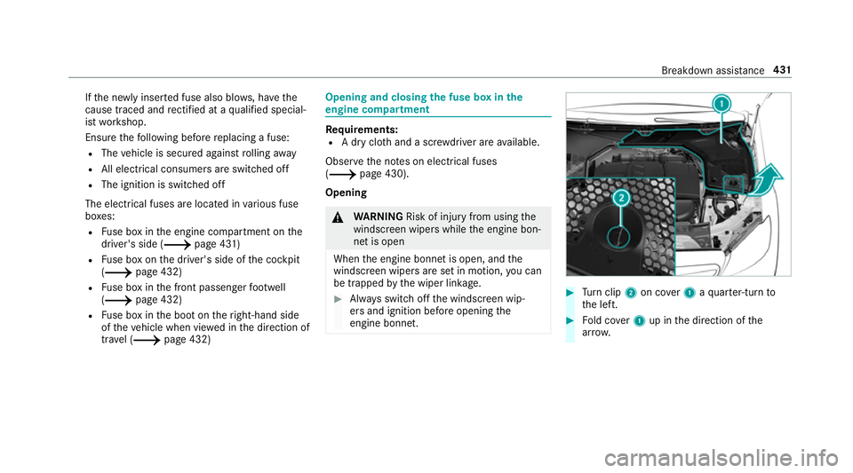
quirements:
R A dry clo thand a sc rewdriver are available.
Obse rveth e no tes on electrical fuses
(0013 page 430).
Opening 000A
WARNING Risk of inju ryfrom using the
windscreen wipers while the engine bon‐
net is open
When the engine bonn etis open, and the
windscreen wipers are set in motion, you can
be trapped bythe wiper linkage. 0007
Alw ays switch off the windscreen wip‐
ers and ignition before opening the
engine bonn et. 0007
Turn clip 2on co ver1 aqu arter-turn to
th e left. 0007
Fold co ver1 up in the direction of the
ar row. Breakdown assis
tance 431
Page 435 of 593
0007
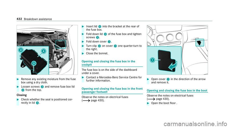
Remo veany existing moisture from the fuse
box using a dry clo th.0007
Loosen scr ews3 and remo vefuse box lid
4 from theto p.
Closing 0007
Check whe ther the seal is positioned cor‐
re ctly in lid 4. 0007
Insert lid 4into the brac ket at there ar of
th e fuse box. 0007
Fold down lid 4ofthe fuse box and tighten
scr ews3. 0007
Fold down co ver1. 0007
Turn clip 2on co ver1 one quarter-turn to
th eright. 0007
Close the bonn et. Opening and closing
the fuse box in the
cockpit The fuse box is on
the side of the dashboard
under a co ver. 0007
Con tact a Mercedes-Benz Service Centre for
fur ther information. Opening and closing
the fuse box in the front
passenger foot we ll Obser
vethe no tes on electrical fuses
(0013 page 430). 0007
Open co ver1 inthe direction of the ar row
and remo veit. Opening and closing
the fuse box in the boot Obser
vethe no tes on electrical fuses
(0013 page 430). 0007
Open the boot floor . 432
Breakdown assis tance
Page 451 of 593
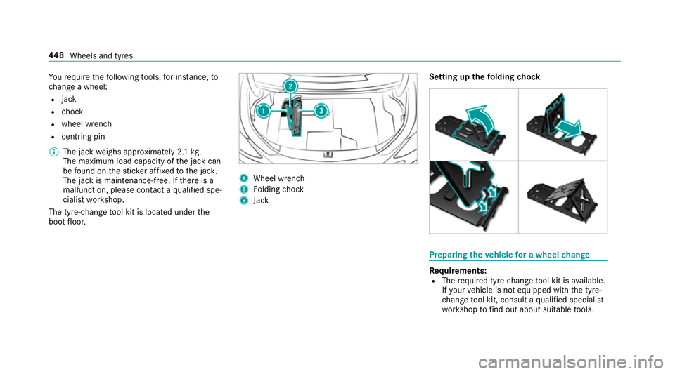
Yo
ure qu ire thefo llowing tools, for ins tance, to
ch ange a wheel:
R jack
R chock
R wheel wrench
R centri ng pin
0009 The jack weighs appr oximately 2.1 kg.
The maximum load capacity of the jack can
be found on thest icke r af fixe dto the jac k.
The jack is maintenance-free. If there is a
malfunction, please conta ct aqualified spe‐
cialist workshop.
The tyre-change tool kit is located under the
boot floor. 1
Wheel wrench
2 Folding chock
3 Jack Setting up
thefo lding chock Prepa
ring theve hicle for a wheel change Re
quirements:
R The requ ired tyre-change tool kit is available.
If yo ur vehicle is not equipped with the tyre-
ch ange tool kit, consult a qualified specialist
wo rkshop tofind out about suitable tools. 448
Wheels and tyres
Page 453 of 593
0007
Attach wheel spanner 3tosoc ket2 and
tighten the hub cap clockwise.
Specified tightening torq ue: 25 Nm. Ra
ising theve hicle when changing a wheel Re
quirements:
R There are no persons in theve hicle.
R The vehicle has been prepared for a wheel
ch ange (0013 page448).
R The hub caps ha vebeen remo ved
( 0013 page449).
Impor tant no tes on using the jack:
R Use only theve hicle-specific jack that has
been tested and appr ovedby Mercedes-Benz
to raise theve hicle.
R The jack is only designed forra ising and
holding theve hicle for a short time while a
wheel is being changed and not for mainte‐
nance workunder theve hicle.
R The jack must be placed on a firm ,fl at and
non-slip sur face. If necessar y,use a lar ge,
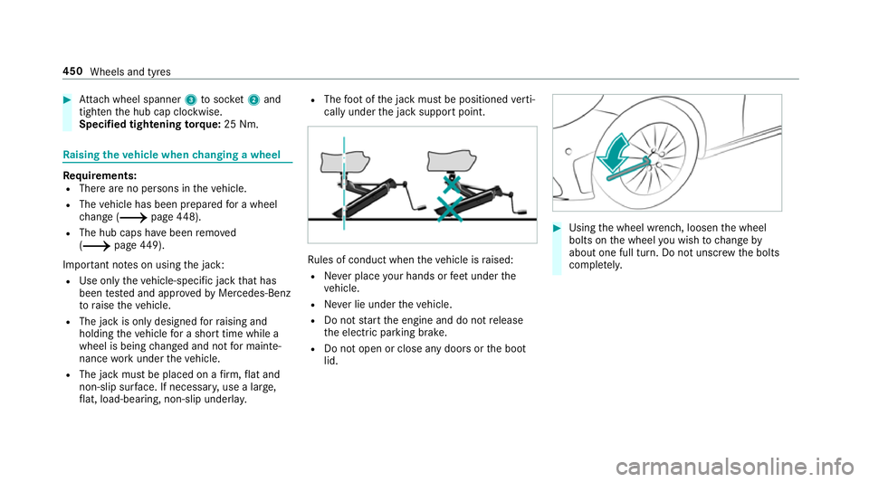
fl at, load-bearing, non-slip unde rlay. R
The foot ofthe jack must be positioned verti‐
cally under the jack support point. Ru
les of conduct when theve hicle is raised:
R Never place your hands or feet under the
ve hicle.
R Never lie under theve hicle.
R Do not start the engine and do not release
th e electric parking brake.
R Do not open or close any doors or the boot
lid. 0007
Using the wheel wrench, loosen the wheel
bolts on the wheel you wish tochange by
about one full turn. Do not unscr ewthe bolts
comple tely. 450
Wheels and tyres
Page 458 of 593
Ve
hicles with a tyre pressure monitoring
sy stem: For a few minutes af ter an emer‐
ge ncy spa rewheel is fitted, the sy stem may
st ill display the tyre pressure of there mo ved
wheel.
Be sure toalso obse rveth efo llowing fur ther
re lated subjects:
R Notes on tyre pressure (0013 page 435)
R Tyre pressure table (0013 page 436) Re
moving the eme rgency spa rewheel The eme
rgency spare wheel is secured in the
emer gency spa rewheel bag in the boot. 0007
Obser vethe information on mounting tyres
(0013 page444). 0007
Open the boot. 0007
Detach thefast ening stra ps. 0007
Unhook there taining spring hooks of thefa s‐
te ning stra ps from the brac kets. 0007
Remo vethe emer gency spa rewheel bag with
th e emer gency spa rewheel. 0007
Open the emer gency spa rewheel bag and
re mo vethe emer gency spa rewheel. Collapsible spa
rewheel Inflating
the collapsible emer gency spare
wheel 000E
NO
TEDama getothe collapsible spare
wheel when lo wering theve hicle Lo
we ring theve hicle without pr eviously
inflating the collapsible spare wheel can
damage its rim. 0007
Inflate the collapsible spare wheel using
th e tyre inflation compressor before
lo we ring theve hicle. 000E
NO
TEOverheating due tothe tyre infla‐
tion compressor running too long 0007
Do not runth e tyre inflation compres‐
sor for longer than eight minutes with‐
out inter ruption. Re
quirements:
R Obser vethe manufacturer's saf ety no tes on
th e tyre inflation compressor label and on
th e tyre sealant bottle.
R Mount the collapsible emer gency spa re
wheel as desc ribed (0013 page 452).
The collapsible emer gency spa rewheel must
be moun ted before it is inflated.
R Remo vethe tyre inflation compressor from
th estow age space under the boot floor
(0013 page414). Wheels and tyres
455
Page 461 of 593
0007
When operating two-w ayradios in the
ve hicle, alw ays connect them tothe
lo w- reflection exterior aerial. 000E
NO
TEInva lidation of the operating per‐
mit due tofailure tocomply wi th the
instructions for ins tallation and use The operating permit may be in
validated if
th e instructions for ins tallation and use of
two-w ayradios are not obser ved. 0007
Only use appr oved frequency bands. 0007
Obser vethe maximum permissible out‐
put po wer in these frequency bands. 0007
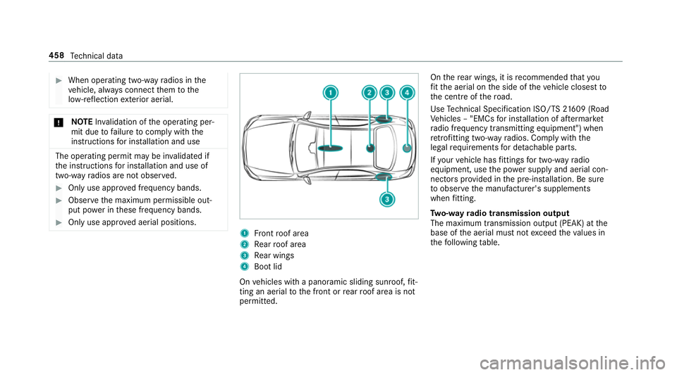
Only use appr oved aerial positions. 1
Front roof area
2 Rear roof area
3 Rear wings
4 Boot lid
On vehicles with a panoramic sliding sunroof, fit‐
ting an ae rial to the front or rear roof area is not
permitted. On
there ar wings, it is recommended that you
fi t th e aerial on the side of theve hicle closest to
th e cent reofthero ad.
Use Tech nical Specification ISO/TS 21609 (Road
Ve hicles – "EMCs for ins tallation of af term arket
ra dio frequency transmitting equipment") when
re trofitting two-w ayradios. Comply with the
legal requirements for de tach able parts.
If yo ur vehicle has fittings for two-w ayradio
equipment, use the po wer supp lyand aerial con‐
nec tors prov ided in the pre-ins tallation. Be sure
to obser vethe manufacturer's supplements
when fitting.
Tw o-w ayradio transmission output
The maximum transmission output (PEAK) at the
base of the aerial must not exceed theva lues in
th efo llowing table. 458
Tech nical da ta
Page 523 of 593
Display messages
Possible causes/consequences and 0050
0050Solutions
Operation only possible in
transmission position P
00CA
Operation only possible in
transmission position N *
Ve hicles with manual transmission: you attem ptedto swivel the ball neck and the transmission is not in neutral
005C. 0007
Shift the transmission toneutral 005C.
00CA Check trailer hitch lock
(whi tedisplay message) *T
he trailer tow hit chis not operational when you are driving with a trailer. 0007
Stop theve hicle immediately, paying attention toroad and traf fic conditions, and switch off the engine. 0007
Uncouple the trailer and secure it against rolling away. 0007
Initiate a new swivelling procedure (0013 page248). 0007
Ifth e ball neck is extended, press and hold the button on the boot lid until the ball neck engages beneath the
bumper. 0007
When the display message disappears, couple up the trailer and drive on. 000A
WARNING Risk of an accident if the ball neck is not loc ked
If th e ball neck is not in the loc ked position, the trailer may come loose. 0007
Pull over and stop theve hicle safely as soon as possible, paying attention toroad and traf fic conditions.
Do not continue driving under any circums tances. 520
Display messa ges and warning/indicator lamps
Page 524 of 593
Display messages
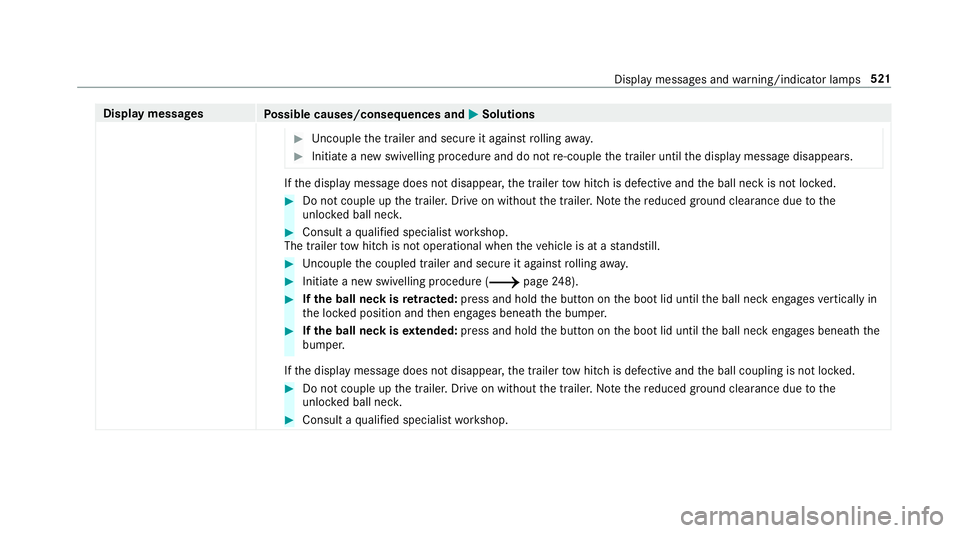
Possible causes/consequences and 0050
0050Solutions 0007
Uncouple the trailer and secure it against rolling away. 0007
Initiate a new swivelling procedure and do not re-couple the trailer until the display message disappears. If
th e display message does not disappear, the trailer tow hit chis defective and the ball neck is not loc ked. 0007
Do not couple up the trailer. Drive on without the trailer. No tethere duced ground clearance due tothe
unlo cked ball nec k. 0007
Consult a qualified specialist workshop.
The trailer tow hit chis not operational when theve hicle is at a standstill. 0007
Uncouple the coupled trailer and secure it against rolling away. 0007
Initiate a new swivelling procedure (0013 page248). 0007
Ifth e ball neck is retracted: press and hold the button on the boot lid until the ball neck engages vertically in
th e loc ked position and then engages beneath the bumper. 0007
Ifth e ball neck is extended: press and hold the button on the boot lid until the ball neck engages beneath the
bumper.
If th e display message does not disappear, the trailer tow hit chis defective and the ball coupling is not loc ked. 0007
Do not couple up the trailer. Drive on without the trailer. No tethere duced ground clearance due tothe
unlo cked ball nec k. 0007
Consult a qualified specialist workshop. Display messages and
warning/indicator lamps 521
Page 527 of 593
Display messages
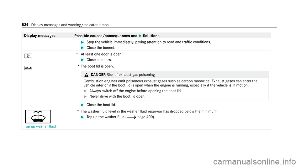
Possible causes/consequences and 0050
0050Solutions 0007
Stop theve hicle immediately, paying attention toroad and traf fic conditions. 0007
Close the bonn et.
0051 *A
t least one door is open. 0007
Close all doors.
0084 *T
he boot lid is open. 000A
DANG ER Risk of exhaust gas poisoning
Combustion engines emit poisonous exhaust gases such as carbon monoxide. Exhaust gases can enter the
ve hicle interior if the boot lid is open when the engine is running, especially if theve hicle is in motion. 0007
Alw ays switch off the engine before opening the boot lid. 0007
Never drive with the boot lid open. 0007
Close the boot lid.
00B2 Top up washer fluid *T
hewasher fluid le vel in thewa sher fluid reser voir has dropped below the minimum. 0007
Top up thewa sher fluid (0013 page 400). 524
Display messages and warning/indicator lamps