trailer MERCEDES-BENZ C-CLASS COUPE 2021 Owner's Guide
[x] Cancel search | Manufacturer: MERCEDES-BENZ, Model Year: 2021, Model line: C-CLASS COUPE, Model: MERCEDES-BENZ C-CLASS COUPE 2021Pages: 549, PDF Size: 9.74 MB
Page 235 of 549
When using a bicycle
rack , set the tyre pressure
fo r increased load on there ar axle of theve hicle.
Fu rther information on the tyre pressure can be
fo und in the tyre pressure table (/ page 401).
Note s on loading
The lar gerth e dis tance between the load's
cent reof gr avity and the ball head, the greater
th e load on the trailer hitch.
Therefore, obser vethefo llowing no tes:
R mount heavy bicycles as close totheve hicle
as possible
R always distribute the load on the bicycle rack
as eve nly as possible across theve hicle's
longitudinal axis
Mercedes-Benz recommends removing all
de tach able parts from bicycles (e.g. bask ets,
ch ild seats, rech arge able bat teries) before load‐
ing them onto the bicycle rack . This will impr ove
th e aerodynamic resis tance and centre of gr avity
of the bicycle rack.
Alw ays secure the bicycles topreve ntthem from
moving around and check them at regular inter‐
va ls to ensure that they are secure. Do not use
tarp aulins or other co vers. The driv‐
ing characteristics and rear view may be
impaired. In addition, aerodynamic resis tance
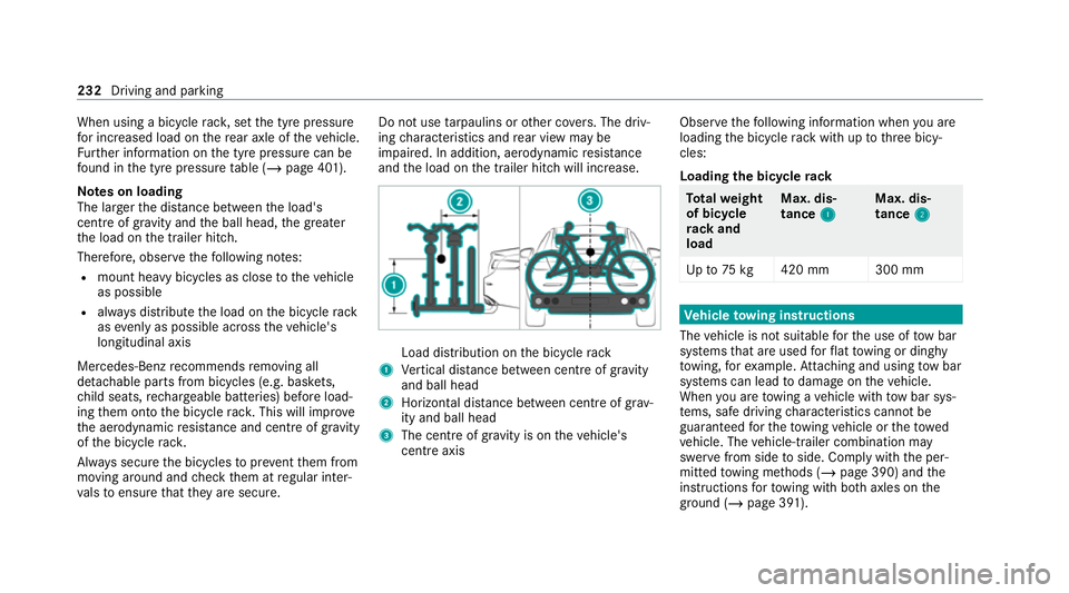
and the load on the trailer hitch will increase. Load distribution on
the bicycle rack
1 Vertical dis tance between centre of gr avity
and ball head
2 Horizon tal dis tance between centre of gr av‐
ity and ball head
3 The centre of gr avity is on theve hicle's
centre axis Obse
rveth efo llowing information when you are
loading the bicycle rack with up tothre e bicy‐
cles:
Loading the bicycle rack To
tal weight
of bicycle
rack and
load Max. dis‐
tance
1 1 Max. dis‐
tance
2 2
Up to75 kg 420 mm 300 mm Ve
hicle towing instructions
The vehicle is not suitable forth e use of tow bar
sy stems that are used forflat towing or ding hy
to wing, forex ample. Attach ing and using tow bar
sy stems can lead todamage on theve hicle.
When you are towing a vehicle with tow bar sys‐
te ms, safe driving characteristics cannot be
guaranteed forth eto wing vehicle or theto wed
ve hicle. The vehicle-trailer combination may
swer vefrom side toside. Comply with the per‐
mitted towing me thods (/ page 390) and the
instructions forto wing with bo thaxles on the
ground ( /page 391). 232
Driving and parking
Page 377 of 549
Re
versing camera and 360° Camera
R Open the camera co ver with the multimedia
sy stem (/ page216).
R Use clean water and a soft clo thtoclean the
came ralens.
R Do not use a high-pressure cleaner.
Ta ilpipes
R Clean with a cleaning agent recommended
fo r Mercedes-Benz, especially in the winter
and af terwa shing theve hicle.
R Do not use acidic cleaning agents.
Tr ailer hitch
R Obse rveth e no tes on care in the trailer hitch
manufacturer's operating instructions.
R Do not clean the ball neck with a high-pres‐
sure cleaner or solvent.
R Remo vetraces of rust on the ball, forex am‐
ple, with a wire brush.
R Remo vedirt with a lint-free clo th.
R After cleaning, lightly oil or grease the ball
head. %
Before using trailers with anti- torsional cou‐
pling, obser vethe manufacturer's operating
instructions. Note
s on care of the interior &
WARNING Risk of inju ryfrom pla stic
parts breaking off af terth e use of sol‐
ve nt-based care products
Ca reand cleaning products con taining sol‐
ve nts can cause su rfaces in the cockpit to
become porous. When the airbags are
deplo yed, plastic parts may break away. #
Do not use any care or cleaning prod‐
ucts containing sol vents toclean the
cockpit. &
WARNING Risk of inju ryor death from
bleached seat belts
Bleaching or dyeing seat belts can se verely
we aken them.
This can, forex ample, cause seat belts to
te ar or fail in an accident. #
Never blea chor dye seat belts. To
avo id damage totheve hicle, obser vethefo l‐
lowing no tes on cleaning and care:
Seat belts R Clean with luk ewarmand soapy water.
R Do not use chemical cleaning agents.
R Do not dry byheating them toove r 80°C or
ex posing them todirect sunlight.
Display
R Switch off the display and let it cool down.
R Clean the sur face carefully wi tha mic rofibre
clo thand a suitable display care product
(TF T-LC D).
R Do not use any other agents.
Plastic trim R Clean with a damp microfibre clo th.
R For heavy soiling: use a cleaner recommen‐
ded for Mercedes-Benz.
R Do not attach sticke rs,fi lms or similar mate‐
ri als. 374
Maintenance and care
Page 395 of 549
R
the electric parking brake cann otbe released
or applied
R vehicles with automatic transmission: the
automatic transmission cannot be shif tedto
position iorj
% Vehicles with automatic transmission: if
th e automatic transmission cann otbe shif‐
te dto position i, orthe multifunction dis‐
play in the instrument clus ter does not show
anything, ha vetheve hicle transpor tedaw ay
( / page 393). A towing vehicle with lifting
equipment is requiredforve hicle transpor ta‐
tion.
* NO
TEDama gedue to to wing away at
exc essively high speeds or over long dis‐
ta nces The driv
etra in could be damaged when tow‐
ing at excessively high speeds or over long
dis tances. #
Atowing speed of 50 km/h must not
be exc eeded. #
Atowing dis tance of 50 km must not be
exc eeded. &
WARNING Risk of accident when towing
a ve hicle which is too heavy
If ano ther vehicle is tow- star ted or towed
aw ay, its weight must not exceed the permis‐
sible gross mass of your ow nve hicle, other‐
wise thefo llowing could occur:
R theto wing eye may become de tach ed.
R theve hicle/trailer combination may
swer veoreve nov erturn. #
If ano ther vehicle is tow- star ted or
to we daw ay, its weight must not exceed
th e permissible gross mass of your own
ve hicle. If a
vehicle must be tow- star ted or towe daw ay,
its permissible gross weight must not exceed the
permissible gross weight of theto wing vehicle. #
Information on the permissible gross mass of
th eve hicle can be found on theve hicle iden‐
tification plate (/ page418). #
Vehicles with automatic transmission: do
not open the driver's door or front passenger
door, otherwise the automatic transmission
automatically shifts toposition j. #
Fittheto wing eye (/ page 395). #
Fasten theto w bar.
* NO
TEDama gedue toincor rect connec‐
tion of theto w bar #
Onlyconnect theto w rope or tow bar to
th eto wing eyes. #
Deactivate the automatic locking mechanism
(/ page 77). #
Do not activate the HOLD function. #
Deactivate tow- aw ay protection
(/ page 93). #
Deactivate Active Brake Assi st
( / page 200). #
Vehicles with automatic transmission:
shift the automatic transmission toposition
i. #
Release the electric parking brake. 392
Breakdown assis tance
Page 396 of 549
&
WARNING Risk of accident due tolimi‐
te d saf ety-re lated functions during the
to wing process
Saf ety-re lated functions are limited or no lon‐
ge rav ailable in thefo llowing situations:
R the ignition is switched off.
R the brake sy stem or po werst eering sys‐
te m is malfunctioning.
R the energy supply or the on-board electri‐
cal sy stem is malfunctioning.
When your vehicle is then towe daw ay, signif‐
icantly more ef fort may be requ ired tosteer
and brake than is no rmally requ ired. #
Use a tow bar. #
Make sure that thesteering wheel can
mo vefreely before towing theve hicle
aw ay. *
NO
TEDama gedue toexcessive tracti ve
po wer If
yo u pull away sharpl y,the tractive po wer
may be too high and theve hicles could be
damaged. #
Pull away slowly and smoo thly. Loading the
vehicle for transport #
Obser vethe no tes on towing away
( / page 391). #
Connect theto w bar totheto wing eye in
order toload theve hicle.
% You can also attach theto w bar tothe trailer
hitch. #
Vehicles with automatic transmission:
shift the automatic transmission toposition
i.
% Ve
hicles with automatic transmission:
th e automatic transmission may be loc ked in
position jintheeve nt of dama getothe
electrical sy stem. Toshift toi , pr ovide the on-board electrical sy
stem with po wer
( / page 388). #
Load theve hicle onto the transpor ter. #
Vehicles with automatic transmission:
shift the automatic transmission toposition
j. #
Use the electric parking brake tosecure the
ve hicle against rolling away. #
Only secure theve hicle bythe wheels.
Ve hicles with ADS PLUS (Adaptive Damping
Sy stem PLUS) &
WARNING Risk of an accident when
transporting vehicles with Adaptive
Damping Sy stem PLUS
When transporting vehicles with Adaptive
Damping Sy stem PLUS, theve hicle/trailer
combination may begin torock andstart to
skid. #
When transporting, ensure that:
R theve hicle has been loaded onto
th e transpor ter cor rectly Breakdown assis
tance 393
Page 398 of 549
Installing
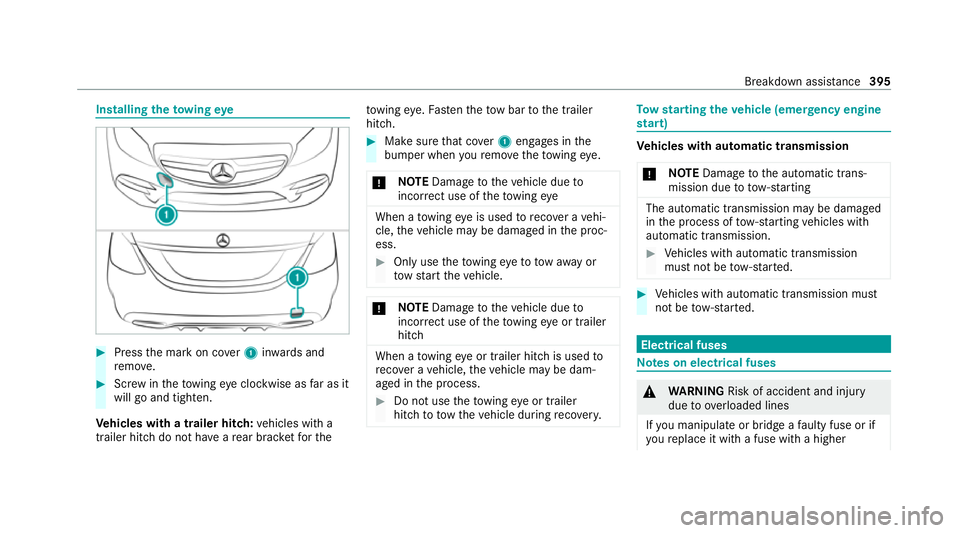
theto wing eye #
Press the mark on co ver1 inwa rds and
re mo ve. #
Screw intheto wing eyeclockwise as far as it
will go and tighten.
Ve hicles with a trailer hitch: vehicles with a
trailer hitch do not ha veare ar brac ketfo rthe to
wing eye. Fasten theto w bar tothe trailer
hitch. #
Make sure that co ver1 engages in the
bumper when youre mo vetheto wing eye.
* NO
TEDama getotheve hicle due to
incor rect use of theto wing eye When a
towing eye is used toreco ver a vehi‐
cle, theve hicle may be damaged in the proc‐
ess. #
Only use theto wing eyeto to waw ay or
to w start theve hicle. *
NO
TEDama getotheve hicle due to
incor rect use of theto wing eye or trailer
hitch When a
towing eye or trailer hitch is used to
re co ver a vehicle, theve hicle may be dam‐
aged in the process. #
Do not use theto wing eye or trailer
hitch to towtheve hicle during reco very. To
w starting theve hicle (eme rgency engine
st art) Ve
hicles with automatic transmission
* NO
TEDama getothe automatic trans‐
mission due to tow-starting The automatic transmission may be damaged
in the process of tow- starting vehicles with
automatic transmission. #
Vehicles with automatic transmission
must not be tow- star ted. #
Vehicles with automatic transmission must
not be tow- star ted. Electrical fuses
Note
s on electrical fuses &
WARNING Risk of accident and inju ry
due to ov erloaded lines
If yo u manipulate or bridge a faulty fuse or if
yo ure place it with a fuse with a higher Breakdown assis
tance 395
Page 404 of 549
#
Adjust the tyre pressure where neces‐
sar y. Ty
re pressure which is too high or too low can:
R Shor tenth e service life of the tyres.
R Cause increased tyre damage.
R Adversely af fect driving characteristics and
th us driving saf ety, e.g. due toaquaplaning. &
WARNING Risk of accident due torepea‐
te d pressure drop in the tyres
The wheels, valves or tyres could be dam‐
aged.
To o low a tyre pressure can lead tothe tyres
bur sting. #
Examine the tyres forfo re ign objects. #
Check whe ther the tyre has a puncture
or theva lve has a leak. #
Ifyo u are unable torectify the damage,
conta ct aqualified specialist workshop. Information on
there commended tyre pressure
fo rth eve hicle's factor y-fitted tyres can be found on
the tyre pressure table on the inside of the
fuel filler flap (/ page 401).
Use a suitable pressure gauge tocheck the tyre
pressure. The outer appearance of a tyre does
not permit any reliable conclusion about the tyre
pressure.
Only cor rect tyre pressures when the tyres are
cold. Conditions for cold tyres:
R The vehicle has been par ked with the tyres
out of direct sunlight for at least thre e hours.
R The vehicle has tr avelled less than 1.6 km.
The vehicle's tyres heat up when driving. As the
te mp erature of the tyres increases, so too does
th e tyre pressure.
Ve hicles with a tyre pressure monitoring sys‐
te m: you can also check the tyre pressure using
th e on-board computer.
Note s on trailer operation
Alw ays inflate there ar axle tyres tothere com‐
mended tyre pressures on the tyre pressure
ta ble for increased load. Ty
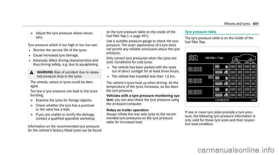
re pressure table The tyre pressure
table is on the inside of the
fuel filler flap. If one or more tyre sizes precede a tyre pres‐
sure, thefo llowing tyre pressure information is
only valid forth ose tyre sizes and their respec‐
tive load condition. Wheels and tyres
401
Page 406 of 549
ing condition (/
page 401). Observethe
no tes on tyre temp erature (/ page 400).
% The values displa yed in the on-board com‐
puter may deviate from those of the tyre
pressure gauge as they referto sea le vel.At
high ele vations, the tyre pressure values
indicated bya pressure gauge are higher
th an those shown bythe on-board computer.
In this case, do not reduce the tyre pressure.
Re starting the ty repressure moni toring sys‐
tem
Re quirements:
R The recommended tyre pressure is cor rectly
set forth ere spective operating status on all
of the wheels (/ page 400).
Re start the tyre pressure monitoring sy stem in
th efo llowing situations:
R The tyre pressure has changed.
R The wheels or tyres ha vebeen changed or
newly fitted. On-boa
rdcompu ter:
4 Service 5
Tyres #
Swipe down wards on Touch Control on the
left-hand side of thesteering wheel.
The Use current tyre pressures as new refer-
ence values? message is shown in the multi‐
function displa y. #
Torestart, press Touch Control on the left-
hand side of thesteering wheel.
The Tyre press. monitor restarted message is
shown in the multifunction displa y.
Cur rent wa rning messages are dele ted and
th eye llow h warning lamp goes out.
Af teryo u ha vebeen driving for a few
minutes, the sy stem checks whe ther the cur‐
re nt tyre pressures are wi thin the specified
ra nge. The cur rent tyre pressures are then
accep ted as refere nce values and monitored.
Be sure toalso pay attention tothefo llowing
re lated topic:
R Notes on tyre pressure (/ page 400) Ty
re pressure loss warning sy stem Fu
nction of the ty repressure loss warning
sy stem
The tyre pressure loss warning sy stem warnsthe
driver bymeans of display messa ges when there
is a se vere tyre pressu reloss.
Sy stem limits
The sy stem may be impaired or may not function
particular lyin thefo llowing situations:
R incor rectly set tyre pressure
R sudden pressure loss caused, forex ample,
by afo re ign object penetrating the tyre
R steady pressure loss in se veral tyres
The sy stem has a restricted or del ayed function
particularly in thefo llowing situations:
R poor ground cond itions, e.g. snow or gr avel
R driving with snow chains
R when adopting a very sporty driving style
with high cornering speeds or sudden accel‐
eration
R driving with a very heavy or lar getrailer Wheels and tyres
403
Page 433 of 549
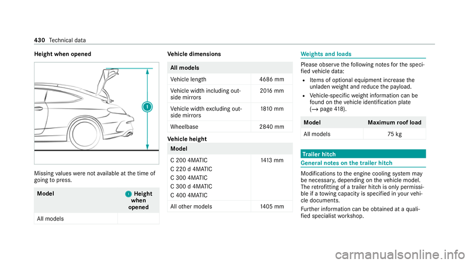
Height when opened
Missing
values werenot available at the time of
going topress. Model
1
1Height
when
opened
All models Ve
hicle dimensions All models
Ve
hicle lengt h4 686 mm
Ve hicle width including out‐
side mir rors 20
16 mm
Ve hicle width excluding out‐
side mir rors 18
10 mm
Wheelbase 2840 mm Ve
hicle height Model
C 200 4MATIC
C 220 d 4MATIC
C 300 4MATIC
C 300 d 4MATIC
C 400 4MATIC
14
13 mm
All other models 1405 mm We
ights and loads Please obser
vethefo llowing no tesfo rth e speci‐
fi ed vehicle data:
R Items of optional equipment increase the
unladen weight and reduce the pa yload.
R Vehicle-specific weight information can be
fo und on theve hicle identification plate
(/ page 418). Model
Maximumroof load
All models 75kg Tr
ailer hitch Gene
ral no tes on the trailer hit ch Modifications
tothe engine cooling sy stem may
be necessar y,depending on theve hicle model.
The retrofitting of a trailer hitch is only pe rmissi‐
ble if a towing capacity is specified in your vehi‐
cle documents.
Fu rther information can be obtained at a quali‐
fi ed specialist workshop. 430
Tech nical da ta
Page 434 of 549
Mounting dimensions
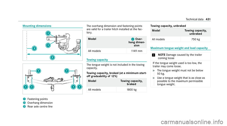
1
Fastening points
2 Overhang dimension
3 Rear axle centre line The
overhang dimension and fastening points
are valid for a trailer hitch ins talled at thefa c‐
to ry. Model
2 2Over‐
hang dimen‐ sion
All model s1 149 mm To
wing capacity The
tongue weight is not included in theto wing
capacity.
To wing capacit y,braked (at a minimum start-
off gradeability of 12%) Model
Towing capacit y,
braked
All models 1800 kg To
wing capacit y,unbraked Model
Towing capacit y,
unbraked
All model s7 50kg Maximum
tongue weight and load capacity *
NO
TEDama gecaused bythe trailer
coming loose If
th eto ngue weight used is too lo w,the
trailer may come loose. #
The tongue weight must not be below
50 kg. #
Use a tongue weight that is as close as
possible tothe maximum permissible
to ngue weight. Te
ch nical da ta431
Page 435 of 549
*
NO
TEDama gecaused bythe bicycle
ra ck coming loose When using a bicycle
rack , bo th th e maximal
to ngue weight and the maximal load capacity
should be obser ved. #
Do not exceed the permissible load
capacity. Obser
vethe additional no tes on load capacity
(/ page 231).
To ngue weight Model
Maximumtongue
we ight
All models 75kg Missing
values werenot available at the time of
going topress.
Load capacity Model
Maximum load
All models Pe
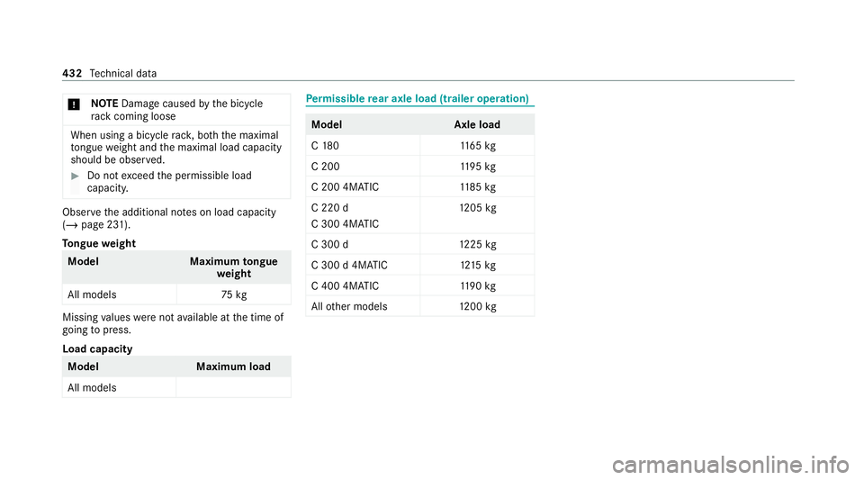
rm issible rear axle load (trailer operation) Model
Axle load
C 18 01 165kg
C 20 01 195kg
C 200 4MATIC 1185 kg
C 220 d
C 300 4MATIC 12
05 kg
C 300 d1 225kg
C 300 d 4MATIC 1215 kg
C 400 4MATIC 1190 kg
All other models 1200 kg 432
Tech nical da ta