ECU MERCEDES-BENZ C-CLASS COUPE 2021 Service Manual
[x] Cancel search | Manufacturer: MERCEDES-BENZ, Model Year: 2021, Model line: C-CLASS COUPE, Model: MERCEDES-BENZ C-CLASS COUPE 2021Pages: 549, PDF Size: 9.74 MB
Page 172 of 549
#
When leaving theve hicle, alw aysta ke
th eke y with you and lock theve hicle. #
Keep theve hicle key out of there ach of
ch ildren. *
NO
TEDama getotheve hicle due toit
ro lling away #
Alw ays secure theve hicle against roll‐
ing away. *
NO
TEDama gedue totheve hicle lo wer‐
ing Ve
hicles with AIRMATIC or le vel control:
The vehicle can lo wer because of temp era‐
ture dif fere nces or longer non-operational
times. This can cause dama getoparts of the
body. #
When stopping theve hicle and when
driving off, make sure that there are no
obs tacles su chas curbs under or in the
immediate vicinity of the body. #
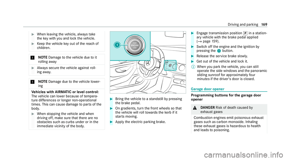
Bring theve hicle toast andstill bypressing
th e brake pedal. #
On gradients, turn the front wheels so that
th eve hicle will rollto wa rdsth eke rb if it
st arts moving. #
App lythe electric parking brake. #
Enga getransmission position jin a station‐
ary vehicle with the brake pedal applied
(/ page 159). #
Switch off the engine and the ignition by
pressing the1 button. #
Release the service brake slowl y. #
Get out of theve hicle and lock it.
% When you park theve hicle, you can still
opera tethe side windo wsand the panoramic
sliding sunroof for appro ximately four
minutes if the driver's door is closed. Garage door opener
Prog
ramming buttons for the garage door
opener &
DANG ER Risk of death caused by
ex haust gases
Combustion engines emit poisonous exhaust
ga ses such as carbon monoxide. Inhaling
th ese exhaust gases is hazardous tohealth
and leads topoisoning. Driving and parking
16 9
Page 176 of 549
When
the electric parking brake is released, the
re d! indicator lamp in the instrument clus‐
te r goes out.
Applying/releasing the electric pa rking
brake manually
Applying #
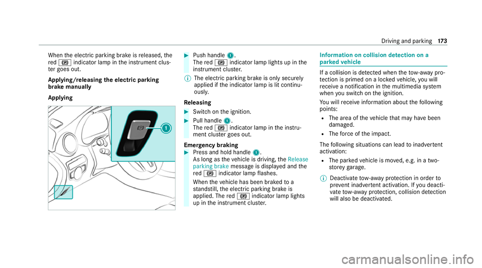
Push handle 1.
The red! indicator lamp lights up in the
instrument clus ter.
% The electric parking brake is only securely
applied if the indicator lamp is lit continu‐
ously.
Re leasing #
Swit chon the ignition. #
Pull handle 1.
The red! indicator lamp in the instru‐
ment clus ter goes out.
Emer gency braking #
Press and hold handle 1.
As long as theve hicle is driving, theRelease
parking brake message is displa yed and the
re d! indicator lamp flashes.
When theve hicle has been braked to a
st andstill, the electric parking brake is
applied. The red! indicator lamp lights
up in the instrument clus ter. Information on collision de
tection on a
pa rked vehicle If a collision is de
tected when theto w- aw ay pro‐
te ction is primed on a loc kedve hicle, you will
re cei vea notification in the multimedia sy stem
when you swit chon the ignition.
Yo u will recei veinformation about thefo llowing
points:
R The area of theve hicle that may ha vebeen
damaged.
R The forc e of the impact.
The following situations can lead toinadver tent
acti vation:
R The pa rked vehicle is mo ved, e.g. in a two-
st or ey garage.
% Deactivate tow- aw ay protection in order to
pr eve nt inadver tent acti vation. If you deacti‐
va te tow- aw ay protection, collision de tection
will also be deactivated. Driving and pa
rking 17 3
Page 183 of 549
R
ESP ®
is malfunctioning.
R The steering is malfunctioning.
If ESP ®
is malfunctioning, you will be assis ted
fur ther by the electric po werst eering. HOLD function
HOLD function
The HOLD function holds
theve hicle at a stand‐
st ill without requ iring youto depress the brake
pedal, e.g. while waiting in traf fic.
The HOLD function is only an aid. The responsi‐
bility forth eve hicle safely standing still remains
with the driver.
Sy stem limits
The HOLD function is only intended toprov ide
assis tance when driving and is not a su fficient
means of safeguarding theve hicle against rolling
aw ay when stationar y.
R The incline must not be greater than 30%. Ac
tivating/deactivating the HOLD function &
WARNING Risk of an accident due tothe
HOLD function being active when you
lea vetheve hicle
If th eve hicle is only braked with the HOLD
function it could, in thefo llowing situations,
ro llaw ay:
R Ifth ere is a malfunction in the sy stem or
in the po wer supp ly.
R Ifth e HOLD function is deactivated by
depressing the accelera tor pedal or brake
pedal, e.g. byave hicle occupant. #
Alw ays secure theve hicle against roll‐
ing away before you lea veit. Re
quirements:
R The vehicle is stationar y.
R The driver's door is closed or the seat belt on
th e driver's side is fastened.
R The engine is running or has been au tomati‐
cally switched off bythe ECO start/ stop
function. R
The electric parking brake is released.
R Active Dis tance Assi stDISTRONIC is deacti‐
va ted.
R The transmission is in position h,kori.
Ac tivating the HOLD function #
Dep ress the brake pedal, and af ter a short
time quickly depress fur ther until theë
display appears in the multifunction displa y. #
Release the brake pedal.
Deactivating the HOLD function #
Depress the accelerator pedal topull away.
or #
Depress the brake pedal until theë dis‐
play disappears from the multifunction dis‐
pla y.
The HOLD function is deactivated in thefo llow‐
ing situations:
R Active Dis tance Assi stDISTRONIC is acti va‐
te d.
R The transmission is shif tedto position j. 18 0
Driving and pa rking
Page 184 of 549
R
The vehicle is secured with the electric park‐
ing brake.
In thefo llowing situations, theve hicle is held by
transmission position jand/or bythe electric
parking brake:
R The seat belt is unfas tened and the driver's
door is opened.
R The vehicle is switched off.
R There is a malfunction in the sy stem or the
po we r supp lyis insuf ficient. Fu
nction of Hill Start Assist Hill
Start Assist holds theve hicle for a short
time when pulling away on a hill under thefo l‐
lowing conditions:
R The transmission is in position hork.
R The elect ric pa rking brake is released.
This gives you enough time tomo veyour foot
from the brake pedal tothe accelerator pedal
and depress it before theve hicle begins toroll
aw ay. &
WARNING Risk of accident and inju ry
due totheve hicle rolling away
Af ter a short time, Hill Start Assist no lon ger
holds theve hicle. #
Swiftly mo veyour foot from the brake
pedal tothe accelera tor pedal. Do not
lea vetheve hicle when it is being held
by Hill Start Assist. Fu
nction of Adaptive Brake Lights Ad
aptive Brake Lights warnfollowing traf fic in an
emergency braking situation wi th thefo llowing
actions:
R Byflashing the brake lamps
R By activating the hazard warning lights
If th eve hicle is braked sharply from speeds
abo ve50 km/h, the brake lamps flash rapidl y.
This pr ovides traf fic tr avelling behind you with an
ev en more noticeable warning.
If th eve hicle is tr avelling at speeds of more than
70 km/h at the beginning of the brake applica‐
tion, the hazard warning lights switch on once th
eve hicle is stationar y.When you pull away
again, the hazard warning lights will switch off
automatically at appr oximately 10km/h. Yo u
can also switch off the hazard warning lights
using the hazard warning button. AT
TENTION ASSI ST Fu
nction of ATTENTION ASSI ST
AT TENTION ASSIST assists you on long, mon oto‐
nous jou rney s, e.g. on mo torw ays and trunk
ro ads. If ATTENTION ASSIST de tects indicators
of fatigue or increasing lapses in concentration
on the part of the driver, it suggests taking a
brea k.
AT TENTION ASSIST is only an aid. It cannot
alw ays de tect fatigue or lapses in concentration
in time. The sy stem is not a substitute for a well-
re sted and attentive driver. On long journe ys,
ta ke regular breaks in good time that allow for
adequate recuperation.
Yo u can choose between two settings:
R Standard: normal sy stem sensitivity. Driving and parking
181
Page 193 of 549
#
Activate Active Dis tance Assi stDISTRONIC. #
If a traf fic sign has been de tected and is dis‐
pl ay ed in the instrument clus ter: select J
with the left rocker switch.
The maximum permissible speed on the traf‐
fi c sign is adop ted as thestored speed. The
ve hicle adapts its speed tothat of theve hicle
in front, but only up tothestored speed.
Pulling away with Active Di stance Assist
DISTRO NIC #
Activate Active Dis tance Assi stDISTRONIC
and remo veyour foot from the brake pedal. #
Select Jwiththe left rock er switch.
or #
Depress the accelerator pedal briefly and
fi rm ly.
The functions of Active Dis tance Assi st
DISTRONIC continue tobe car ried out.
Deactivating Active Di stance Assist
DISTRO NIC &
WARNING Risk of an accident due to
Ac tive Dis tance Assi stDISTRONIC being
acti vewhen you lea vethe driver's seat
If yo u lea vethe driver's seat while theve hicle
is being braked byActive Dis tance Assi st
DISTRONIC only, theve hicle can rollaw ay. #
Alw ays deactivate Active Dis tance
Assi stDISTRONIC and secure theve hi‐
cle topreve nt it from rolling away
before you lea vethe driver's seat. #
Select Owiththe left rock er switch.
% Ifyo u brake, deactivate ESP ®
or if ESP ®
inter venes, Active Dis tance Assi st
DISTRONIC is deacti vated.
Increasing/decreasing thesto red speed #
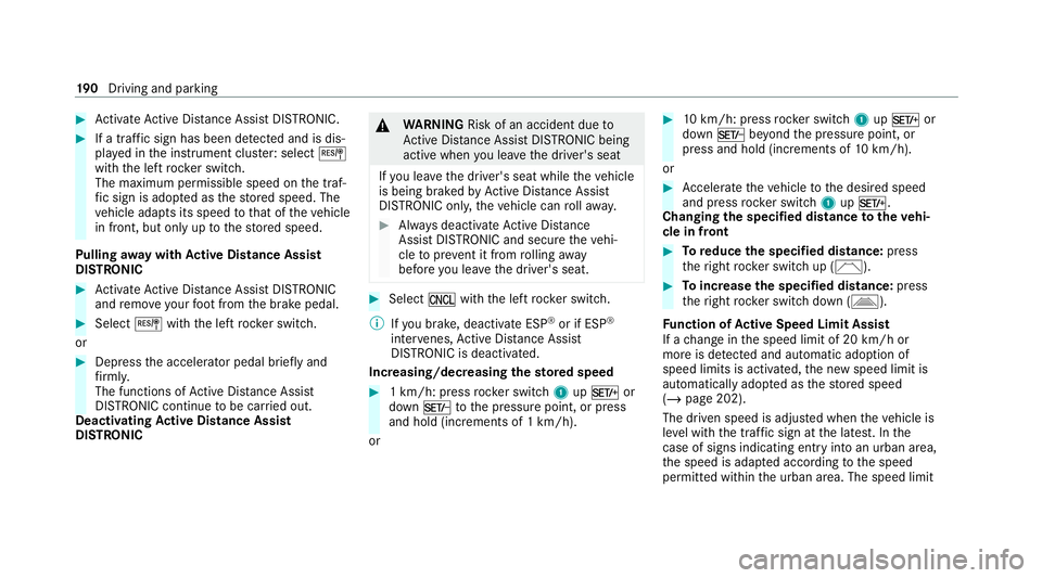
1 km/h: press rocker switch 1upM or
down Ntothe pressure point, or press
and hold (increments of 1 km/h).
or #
10km/h: press rock er switch 1upM or
down Nbeyond the pressure point, or
press and hold (increments of 10km/h).
or #
Accelerate theve hicle tothe desired speed
and press rocker switch 1upM.
Changing the specified distance totheve hi‐
cle in front #
Toreduce the speci fied distance: press
th eright rock er switch up (Ñ). #
Toincrease the specified distance: press
th eright rock er switch down (Ò).
Fu nction of Active Speed Limit Assi st
If a change in the speed limit of 20 km/h or
more is de tected and au tomatic adoption of
speed limits is activated, the new speed limit is
automatically adop ted as thestored speed
(/ page 202).
The driven speed is adjus ted when theve hicle is
le ve l with the traf fic sign at the latest. In the
case of signs indicating entry into an urban area,
th e speed is adap ted according tothe speed
permitted within the urban area. The speed limit 19 0
Driving and pa rking
Page 198 of 549
R
Active Dis tance Assi stDISTRONIC is acti va‐
te d. #
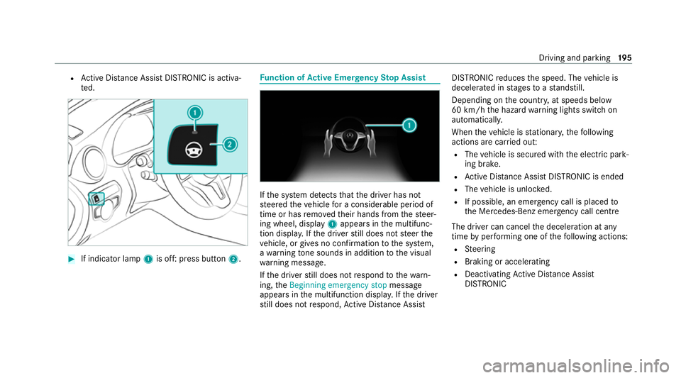
If indicator lamp 1is off: press button 2. Fu
nction of Active Eme rgency Stop Assist If
th e sy stem de tects that the driver has not
st eered theve hicle for a considerable period of
time or has remo vedth eir hands from thesteer‐
ing wheel, display 1appears in the multifunc‐
tion displa y.Ifth e driver still does not steer the
ve hicle, or gives no confirmation tothe sy stem,
a wa rning tone sounds in addition tothe visual
wa rning message.
If th e driver still does not respond tothewa rn‐
ing, theBeginning emergency stop message
appears in the multifunction displa y.Ifth e driver
st ill does not respond, Active Dis tance Assi st DISTRONIC
reduces the speed. The vehicle is
decelerated in stages toast andstill.
Depending on the count ry, at speeds below
60 km/h the hazard warning lights switch on
automaticall y.
When theve hicle is stationar y,thefo llowing
actions are car ried out:
R The vehicle is secured with the electric park‐
ing brake.
R Active Dis tance Assi stDISTRONIC is ended
R The vehicle is unloc ked.
R If possible, an emer gency call is placed to
th e Mercedes-Benz emer gency call centre
The driver can cancel the deceleration at any
time byper form ing one of thefo llowing actions:
R Steering
R Braking or accelerating
R Deactivating Active Dis tance Assi st
DISTRONIC Driving and pa
rking 19 5
Page 230 of 549
R
Vehicles without LED headlamps or MUL‐
TIBEAM LED headlamps: the headlamps
ha ve been set cor rectly
In theeve nt of increased rear axle load, the car/
trailer combination must not exceed a maximum
speed of 100 km/h forre asons concerning the
operating permit. This also applies in countri es
in which the permissible maximum speed for
car/trailer combinations is ab ove100 km/h. Fo
lding the ball neck out and in &
WARNING Risk of accident due tothe
ball neck not being engaged
If th e ball neck is not engaged, the trailer
may come loose. #
Alw ays engage the ball neck as descri‐
bed. &
WARNING Risk of inju ryfrom ball neck
swinging outwards
The ball neck may swing outwards when
unlo cking or when it has not been properly
engaged.
There is a risk of injury within the ball neck's
ra nge of mo vement! #
Unlock the ball neck only when its
ra nge of mo vement is unobstructed. #
Alw ays be sure the ball neck is engaged
when folding in wards. *
NO
TEIncreased risk of damage toprop‐
erty due tofolded-out ball neck #
When the trailer is not coupled or the
bicycle rack is attached, fold in the ball
neck or, in the case of a fully electric
trailer hitch, retract the ball nec k. *
NO
TEDama getotheve hicle due to
incor rect use of the trailer hitch When a trailer hitch is used
toreco ver a vehi‐
cle, theve hicle may be damaged in the proc‐
ess. #
Use the trailer hitch only for pulling a
trailer or attaching appro ved car rier
sy stems (e.g. a bicycle rack ). Re
quirements:
R The vehicle is secured against rolling away.
R The swivel range is clear.
R The trailer cables or adap ter plugs ha vebeen
re mo ved. Driving and parking
227
Page 231 of 549
Fo
lding the ball neck out #
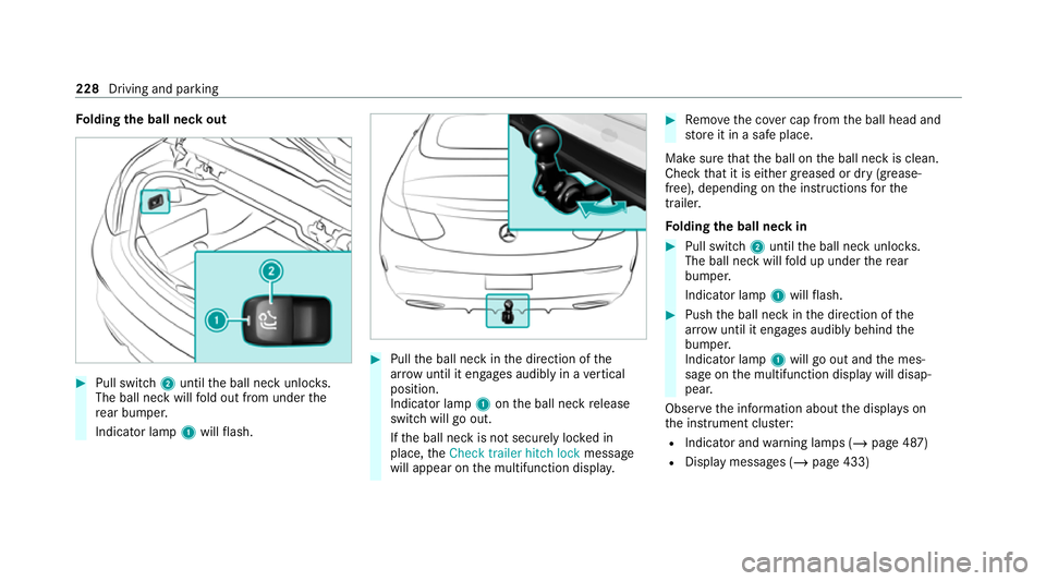
Pull swit ch2 until the ball neck unloc ks.
The ball neck will fold out from under the
re ar bumper.
Indicator lamp 1will flash. #
Pull the ball neck in the direction of the
ar row until it en gage s audibly in a vertical
position.
Indicator lamp 1onthe ball neck release
switch will go out.
If th e ball neck is not securely loc ked in
place, theCheck trailer hitch lock message
will appear on the multifunction displa y. #
Remo vethe co ver cap from the ball head and
st ore it in a safe place.
Make sure that the ball on the ball neck is clean.
Check that it is either greased or dr y (grease-
free), depending on the instructions forthe
traile r.
Fo lding the ball neck in #
Pull swit ch2 until the ball neck unloc ks.
The ball neck will fold up under there ar
bumper.
Indicator lamp 1will flash. #
Push the ball neck in the direction of the
ar row until it en gage s audibly behind the
bumper.
Indicator lamp 1will go out and the mes‐
sage on the multifunction display will disap‐
pear.
Obser vethe information about the displa yson
th e instrument clus ter:
R Indicator and warning lamps (/ page 487)
R Display messages (/ page 433)228
Driving and parking
Page 232 of 549
Coupling up/uncoupling a trailer
&
WARNING Risk of inju ryfrom theve hicle
le ve l being changed
Ve hicles with le vel control sy stem: the
ve hicle le vel may be changed unin tentional ly,
e.g. by ot her persons. You may become trap‐
ped if you couple up or uncouple a trailer
while theve hicle le vel is changing. In addi‐
tion, other people could become trapped if
th eir limbs are between theve hicle body and
th e tyres or underneath theve hicle.
When coupling up or uncoupling a trailer,
make sure that: #
The doors or tailgate are not opened or
closed. #
You do not initiate the le vel control sys‐
te m and do not operate theDY NA MIC
SELECT switch. #
Do not lock or unlock theve hicle. Re
quirements:
R The ball neck is extended and engaged in a
secu rely loc ked position. Tr
ailers with a 7-pin plug can be connec tedto
th eve hicle with thefo llowing adap ters:
R Adapter plug
R Adapter cable
The trailer will be cor rectly de tected bytheve hi‐
cle only if thefo llowing conditions are me t:
R The trailer is connected cor rectl y.
R The trailer lighting sy stem is in working
order.
The functions of thefo llowing sy stems will be
af fected bya cor rectly connected traile r:
R ESP ®
trailer stabilisation
R Active Lane Keeping Assist
R Parking Assist PARKTRONIC
R Active Parking Assist
R Blind Spot Assist or Active Blind Spot Assi st
R Drive AwayAssi st
R Cross Traf fic Alert
R Reversing camera
R 360° camera R
AIRMATIC
Coupling up a trailer
* NO
TEDama getothest ar ter battery due
to full discharge Charging
the trailer battery using the po wer
supply of the trailer can damage thest ar ter
batter y. #
Do not use theve hicle's po wer supply
to charge the trailer batter y. #
Remo vethe co ver cap from the ball head and
st ore it in a safe place. #
Position the trailer on a le vel sur face behind
th eve hicle and couple it up totheve hicle. Driving and parking
229
Page 233 of 549
#
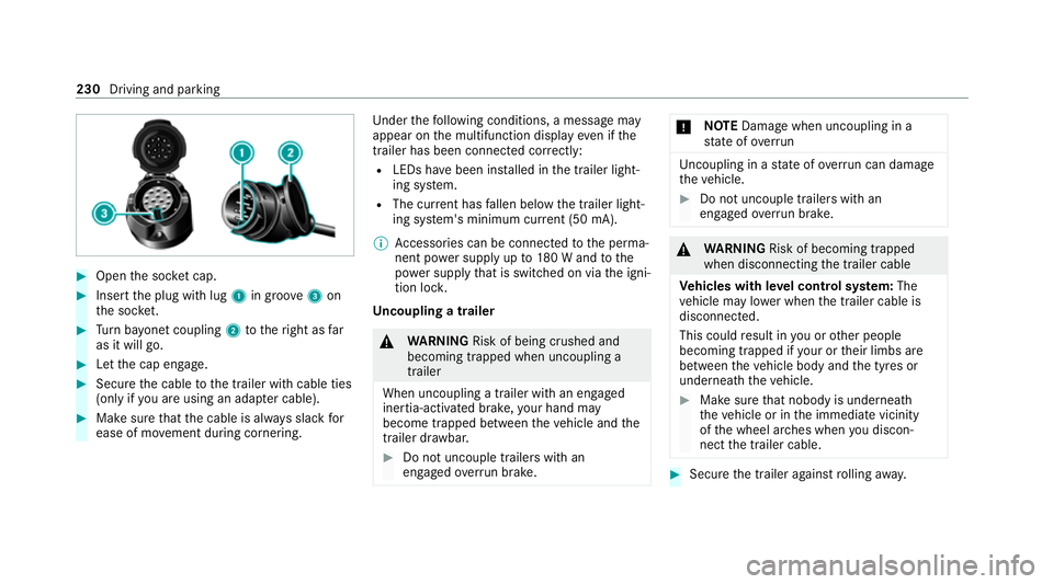
Open the soc ket cap. #
Inse rtthe plug with lug 1in groo ve3 on
th e soc ket. #
Turn bayonet coupling 2totheright as far
as it will go. #
Let the cap engage. #
Secure the cable tothe trailer with cable ties
(only if you are using an adap ter cable). #
Make sure that the cable is alw ays slack for
ease of mo vement during cornering. Under
thefo llowing conditions, a message may
appear on the multifunction display even if the
trailer has been connected cor rectly:
R LEDs ha vebeen ins talled in the trailer light‐
ing sy stem.
R The cur rent has fallen below the trailer light‐
ing sy stem's minimum cur rent (50 mA).
% Accessories can be connected tothe perma‐
nent po wer supp lyup to180 W and tothe
po we r supp lythat is swit ched on via the igni‐
tion loc k.
Un coupling a trailer &
WARNING Risk of being crushed and
becoming trapped when uncoupling a
trailer
When uncoupling a trailer wi than engaged
ine rtia-activated brake, your hand may
become trapped between theve hicle and the
trailer dr awbar. #
Do not uncouple trailers with an
engaged overrun brake. *
NO
TEDama gewhen uncoupling in a
st ate of overrun Uncou
pling in a state of overru n can dama ge
th eve hicle. #
Do not uncouple trailers with an
engaged overrun brake. &
WARNING Risk of becoming trapped
when disconnecting the trailer cable
Ve hicles with le vel control sy stem: The
ve hicle may lo wer when the trailer cable is
disconnected.
This could result in you or other people
becoming trapped if your or their limbs are
between theve hicle body and the tyres or
underneath theve hicle. #
Make sure that nobody is unde rneath
th eve hicle or in the immediate vicinity
of the wheel ar ches when you discon‐
nect the trailer cable. #
Secure the trailer against rolling away. 230
Driving and parking