sensor MERCEDES-BENZ C-CLASS SALOON 2011 Workshop Manual
[x] Cancel search | Manufacturer: MERCEDES-BENZ, Model Year: 2011, Model line: C-CLASS SALOON, Model: MERCEDES-BENZ C-CLASS SALOON 2011Pages: 401, PDF Size: 9.74 MB
Page 285 of 401
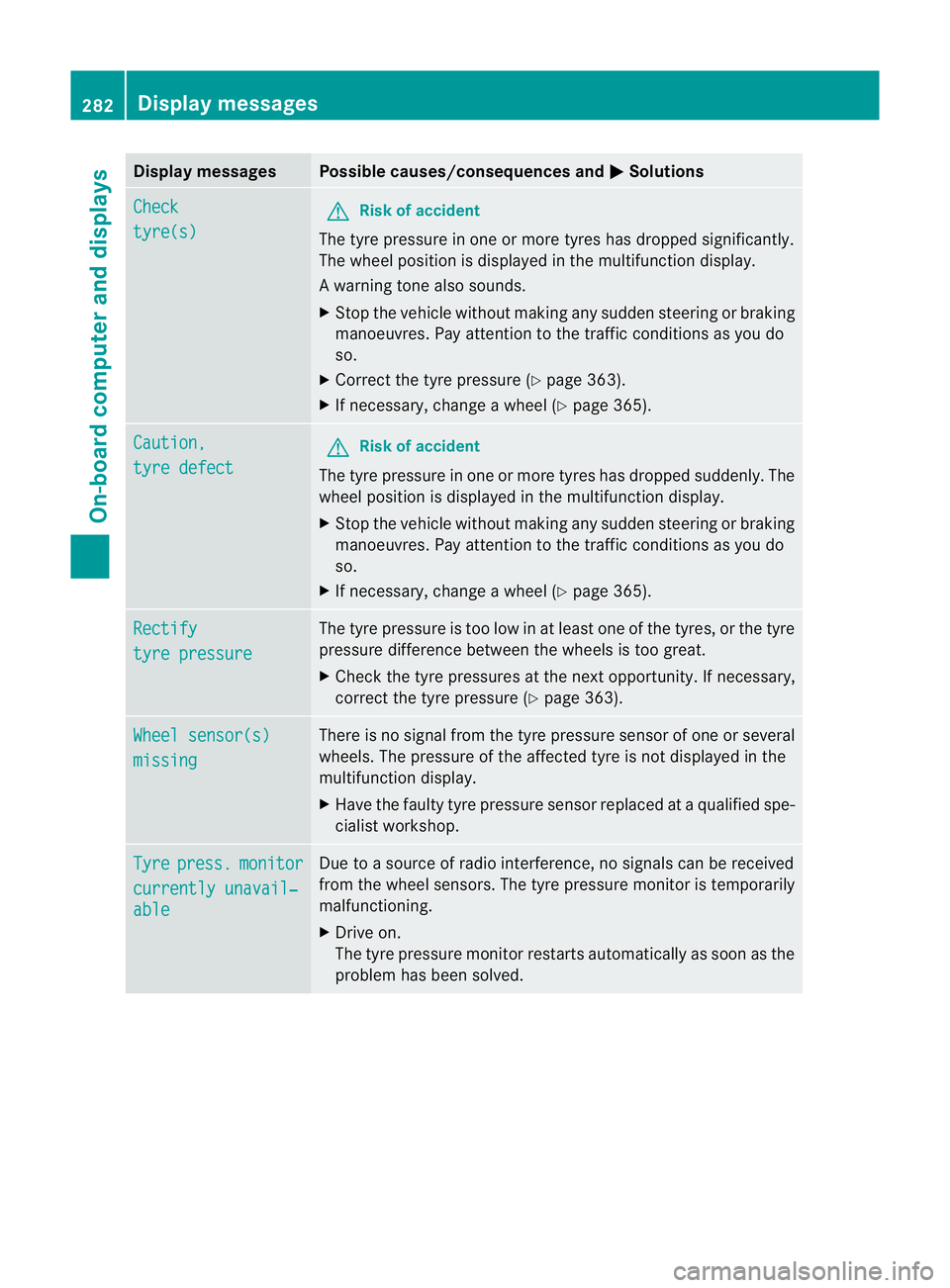
Display messages Possible causes/consequences and
M Solutions
Check
tyre(s) G
Risk of accident
The tyre pressure in one or more tyres has dropped significantly.
The wheel position is displayed in the multifunction display.
Aw arning tone also sounds.
X Stop the vehicle without making any sudde nsteering or braking
manoeuvres .Pay attentio nto the traffic conditions as you do
so.
X Correct the tyre pressure (Y page 363).
X If necessary, change a wheel (Y page 365).Caution,
tyre defect G
Risk of accident
The tyre pressure in one or more tyres has dropped suddenly. The
wheel position is displayed in the multifunction display.
X Stop the vehicle without making any sudden steering or braking
manoeuvres. Pay attention to the traffic conditions as you do
so.
X If necessary, change a wheel (Y page 365).Rectify
tyre pressure The tyre pressure is too low in at least one of the tyres, or the tyre
pressure difference between the wheels is too great.
X
Check the tyre pressures at the next opportunity. If necessary,
correct the tyre pressure (Y page 363).Wheel sensor(s)
missing There is no signal from the tyre pressure sensor of one or several
wheels. The pressure of the affected tyre is not displayed in the
multifunction display.
X
Have the faulty tyre pressure sensor replaced at a qualified spe-
cialist workshop. Tyre press. monitor
currently unavail‐
able Due to a source of radio interference, no signals can be received
from the wheel sensors. The tyre pressure monitor is temporarily
malfunctioning.
X
Drive on.
The tyre pressure monitor restarts automatically as soon as the
problem has been solved. 282
Display messagesOn-board computer and displays
Page 301 of 401
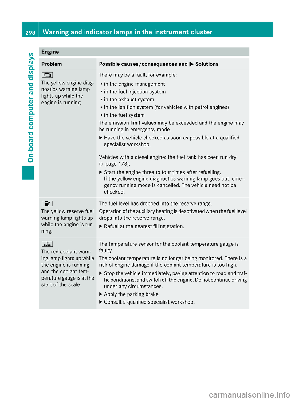
Engine
Problem Possible causes/consequences and
M Solutions
;
The yellow engine diag-
nostics warning lamp
lights up while the
engine is running. There may be a fault, for example:
R
in the engine management
R in the fuel injection system
R in the exhaust system
R in the ignition system (for vehicles with petrol engines)
R in the fuel system
The emission limit values may be exceeded and the engin emay
be running in emergency mode.
X Have the vehicle checked as soon as possible at a qualified
specialist workshop. Vehicles with a diesel engine: the fuel tan
khas been run dry
(Y page 173).
X Start the engine three to four times after refuelling.
If the yellow engine diagnostics warning lamp goes out, emer-
gency running mode is cancelled. The vehicle need no tbe
checked. 8
The yellow reserve fuel
warning lamp lights up
while the engine is run-
ning.
The fuel level has dropped into the reserve range.
Operation of the auxiliary heating is deactivated when the fuel level
drops into the reserve range.
X
Refuel at the nearest filling station. ?
The red coolant warn-
ing lamp lights up while
the engine is running
and the coolant tem-
perature gauge is at the
star
toft he scale. The temperature sensor for the coolant temperature gauge is
faulty.
The coolant temperature is no longer being monitored. There is a
risk of engine damage if the coolant temperature is too high.
X
Stop the vehicle immediately, paying attention to road and traf-
fic conditions, and switch off the engine. Do not continue driving
under any circumstances.
X Apply the parking brake.
X Consult a qualified specialist workshop. 298
Warning and indicator lamps in the instrument clusterOn-board computer and displays
Page 328 of 401

must display less than 70
†.Otherwise, you
could be scalded if hot coolant escapes. X
Slowly tur ncap : half a turn anti-clock-
wise and allow excess pressure to escape.
X Turn cap :further anti-clockwise and
remove it.
If the coolant is at the level of marker bar
= in the fille rneck when cold, there is
enough coolant in coolant expansion
tank ;.
If the coolant level is approximately 1.5 cm
above marker bar =in the filler neckw hen
warm, there is enough coolant in coolant
expansion tank ;.
X If necessary, top up with coolant that has
been tested and approved by Mercedes-
Benz.
X Replace cap :and turn it clockwise as far
as it will go.
For further information on coolant, see
(Y page 383).
Windscreen washer system and head-
lamp cleaning system The washer fluid reservoir is used for both the
windscreen washer system and the headlamp
cleaning system.
i
Components and service products must
be matched. Mercedes-Benz recommends
that you use products tested and approved
by Mercedes-Benz. They are listed in this
Mercedes-Ben zOwner's Manual in the
appropriate section. You can identify service products approved
by Mercedes-Ben
zby th efollowing inscrip-
tions on the container:
R MB-Freigabe (e.g. MB-Freigabe 371.0)
R MB-Approval (e.g. MB-Approval 371.0)
Other labels and recommendations that
make reference to quality level or a speci-
fication according to an MB Sheet no. (e.g.
MB 371.0) are not necessarily approved by
Mercedes-Benz.
You can obtain further information from
any Mercedes-Benz Service Centre. G
WARNING
Windscreen washer fluid is highly flammable.
Fire, naked flames and smoking are prohibi-
ted when handling washer fluid concentrate.
! Only use washer fluid concentrate which
is suitable for plastic lamp lenses. Unsuit-
able washer fluid concentrate could dam-
age the plastic lamp lenses of the head-
lamps.
! Do not use distilled or de-ionised water in
the washer fluid reservoir. Otherwise, the
level sensor may be damaged.
i Add windscreen washer concentrate, e.g.
MB SummerFit, to the washer fluid all year
round. Example: washer fluid reservoir
X
Mix the windscreen washer fluid in a con-
tainer beforehand.
X At temperatures above freezing: fill the
washer fluid reservoir with amix of water Engine compartment
325Maintenance and care Z
Page 333 of 401
the windscree
northe wiper blades. On vehi-
cles with KEYLESS-GO, press the Start/Stop
button repeatedly until all indicator lamps in
the instrument cluster have gone off. The
windscreen wipers could otherwise move and
injure you.
! Only fold the windscreen wipers away
from the windscreen when vertical. Other-
wise, you will damage the bonnet.
! Do not pull on the wiper blade. Otherwise,
the wiper blade could be damaged.
! Do not clean wiper blades too often and
do not rub them too hard. Otherwise, the
graphite coating could be damaged. This
could cause wiper noise.
X Fold the wiper arms away from the wind-
screen.
X Cleant he wiper blades carefully using a
damp cloth.
X Fold the windscreen wipers back again
before switching on the ignition.
! Hold the wiper arm securely when folding
back. The windscreen could be damaged if
the wiper arm hits against it suddenly.
Cleaning the exterior lighting X
Cleant he plastic lenses of the exterior
lighting using a wet sponge and a mild
cleaning agent, e.g. Mercedes-Ben zcar
shampoo or cleaning cloths.
! Only use cleaning agents or cleaning
cloths that are suitable for plastic lenses.
Unsuitable cleaning agents or cleaning
cloths could scratch or damage the plastic
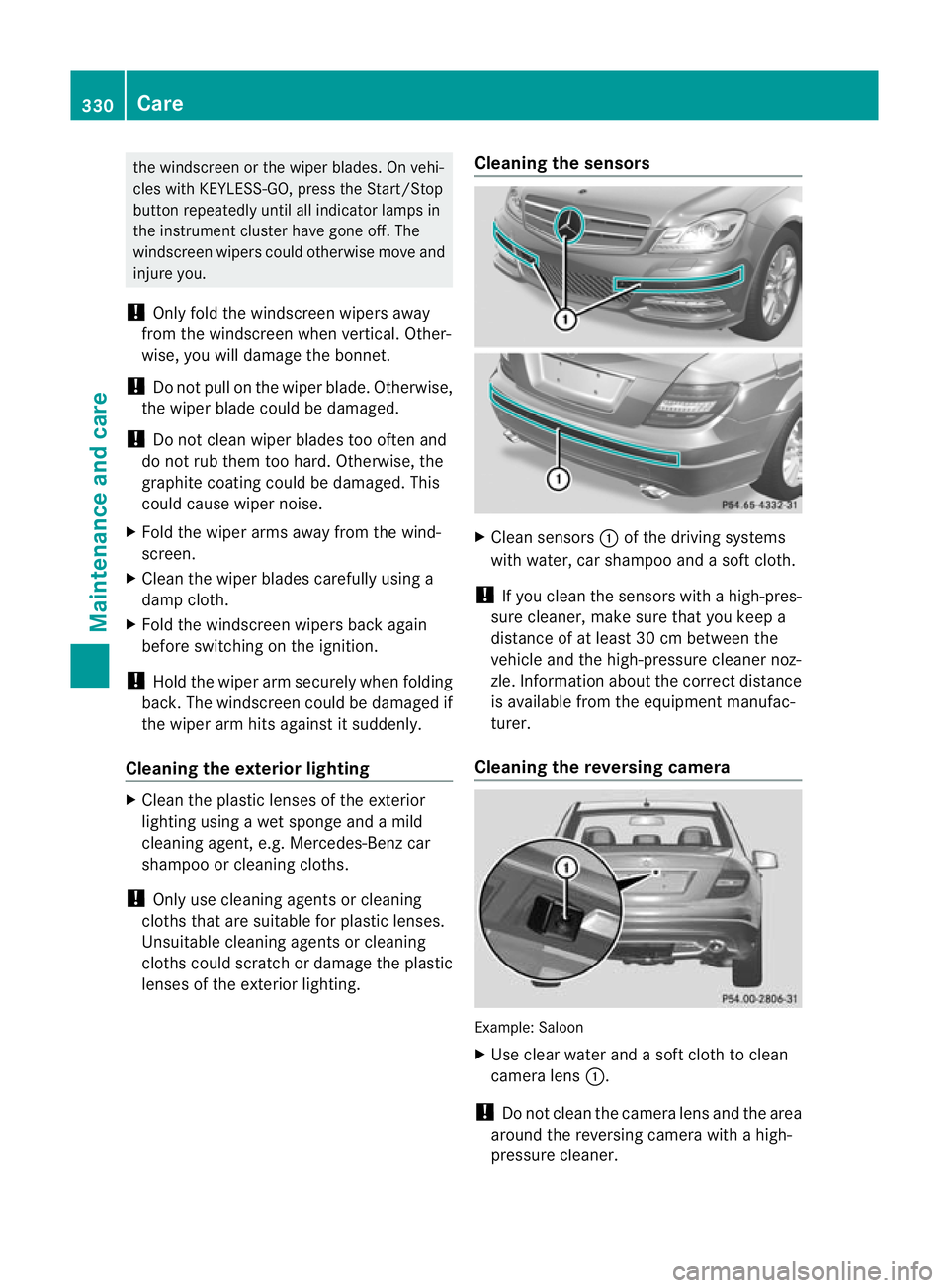
lenses of the exterior lighting. Cleaning the sensors
X
Clean sensors :of the driving systems
with water, car shampoo and a sof tcloth.
! If you clean the sensors with a high-pres-
sure cleaner, make sure that you keep a
distance of at least 30 cm between the
vehicle and the high-pressure cleaner noz-
zle. Information about the correct distance
is available fro mthe equipment manufac-
turer.
Cleaning the reversing camera Example: Saloon
X
Use clear water and a soft cloth to clean
camera lens :.
! Do not clean the camera lens and the area
around the reversing camera with a high-
pressure cleaner. 330
CareMaintenance and care
Page 348 of 401

X
Tighten the wheel bolts evenly in a cross-
wise pattern in the sequence indicated
(: toA ). The tightening torque must be
130 Nm. G
WARNING
Have the tightening torque checked immedi-
ately after a wheel is changed. The wheels
could work loose if they are not tightened to
a torque of 130 Nm.
X Turn the jack back to its initial position and
store it together with the rest of the tyre-
change tool kit in the boot/luggage com-
partment.
X Transport the faulty wheel in the boot/lug-
gage compartment.
or
X Depending on the size of the wheel, you
may also be able to secure the faulty wheel
in the spare wheel well. In this case, you
will have to remove the stowage well casing
from the spare wheel well and stow it
securely in the boot/luggage compart-
ment.
i When you are driving with the collapsible
emergency spare wheel fitted, the tyre
pressure loss warning system or the tyre
pressure monitor cannot function reliably.
Only restart the tyre pressure loss warning
system/tyre pressure monitor when the
defective wheel has been replaced with a
new wheel.
Vehicles with tyre pressure monitor: all fit-
ted wheels must be equipped with func- tioning sensors. The defective wheel
should no longer be in the vehicle. MOExtended tyres (tyres with run-flat
characteristics)
MOExtended tyres (tyres with run-flat char-
acteristics) allow you to continue driving the
vehicle even when one or more tyres lose all
air pressure.
MOExtended tyres may only be used in con-
junction with the activated tyre pressure loss
warning system or with the tyre pressure
monitor.
The maximum permissible distance which
can be driven in run-flat mode depends on the
load in the vehicle. It is 80 km if the vehicle
is partially laden and 30 km if fully laden.
The maximum permissible distance which
can be driven in run-flat mode is counted from
the moment the tyre pressure loss warning
appears in the multifunction display.
You must not exceed a maximum speed of
80 km/h. G
WARNING
The handling characteristics of your vehicle
deteriorate in run-flat mode, for example:
R when cornering
R when braking
R when accelerating rapidly
Adapt your driving style accordingly and avoid
sudden changes in direction and sudden
acceleration, as well as driving over obstacles
(i.e. kerbs, potholes), and driving off-road.
This is particularly the case when the vehicle
is heavily laden.
The maximum permissible distance that can
be driven in run-flat mode depends to a large
exten tonthe loads placed on the vehicle. It
can be shorter due to high speeds, a heavy
load, sudden changes in direction, the road
surface condition, outside temperature, etc.,
or further if you drive carefully and conserva-
tively. Flat tyre
345Breakdown assistance
Z
Page 366 of 401
tyres is set correctly for the respective
operating conditions.
X Observe the notes in the section on tyre
pressures (Y page 361). G
WARNING
The tyre pressure loss warning syste mcan
only give reliable warnings if you have set the
correct tyre pressure.
If an incorrect tyre pressure is set, these
incorrect values will be monitored.
At yre with insufficien tpressure results in
vehicle instability when driving, thus increas-
ing the risk of an accident.
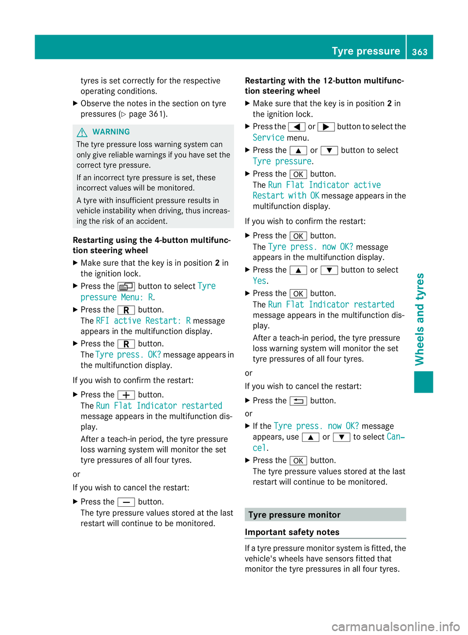
Restarting using the 4-button multifunc-
tion steering wheel
X Make sure that the key is in position 2in
the ignitio nlock.
X Press the Vbutton to select Tyre pressure Menu: R .
X Press the Cbutton.
The RFI active Restart: R message
appears in the multifunction display.
X Press the Cbutton.
The Tyre press. OK? message appears in
the multifunction display.
If you wish to confirm the restart:
X Press the Wbutton.
The Run Flat Indicator restarted message appears in the multifunction dis-
play.
After a teach-in period, the tyre pressure
loss warning system will monitor the set
tyre pressures of all four tyres.
or
If you wish to cancel the restart:
X Press the Xbutton.
The tyre pressure values stored at the last
restart will continue to be monitored. Restarting with the 12-button multifunc-
tion steering wheel
X
Make sure that the key is in position 2in
the ignition lock.
X Press the =or; button to select the
Service menu.
X Press the 9or: button to select
Tyre pressure .
X Press the abutton.
The Run Flat Indicator active Restart with OK message appears in the
multifunction display.
If you wish to confirm the restart:
X Press the abutton.
The Tyre press. now OK? message
appears in the multifunction display.
X Press the 9or: button to select
Yes .
X Press the abutton.
The Run Flat Indicator restarted message appears in the multifunction dis-
play.
After a teach-in period, the tyre pressure
loss warning system will monitor the set
tyre pressures of all four tyres.
or
If you wish to cancel the restart:
X Press the %button.
or
X If the Tyre press. now OK? message
appears, use 9or: to select Can‐ cel .
X Press the abutton.
The tyre pressure values stored at the last
restart will continue to be monitored. Tyre pressure monitor
Important safety notes If a tyre pressure monitor system is fitted, the
vehicle's wheels have sensors fitted that
monitor the tyre pressures in all four tyres. Tyre pressure
363Wheels and tyres Z
Page 367 of 401
The tyre pressure monitor warns you when
the pressure drops in one or more of the
tyres. The tyre pressure monitor only func-
tions if the correct sensors are fitted to all
wheels. G
WARNING
The tyre pressure monitor does not warn you
of an incorrectly set tyre pressure. The table
on the inside of the fuel filler flap will help you
decide whether the tyre pressures should be
corrected.
The tyre pressure monitor is not able to warn
you of a sudden loss of pressure, e.g. if the
tyre is penetrated by a foreign object. In the
event of a sudden loss of pressure, bring the
vehicle to a halt by braking carefully. Do not
make any sudden steering movements when
doing so.
Information on tyre pressures is displayed in
the multifunction display .After a few minutes
of driving, the current tyre pressure of each
tyre is show ninthe multifunction display.
i The tyre pressure values indicated by the
on-board computer may differ from those
measured at a filling station with a pressure
gauge. The tyre pressures shown by the on-
board computer refer to those measured at
sea level. At high altitudes, the tyre pres-
sure values indicated by a pressure gauge
are higher than those shown by the on-
board computer. In this case, do not reduce
the tyre pressures.
i The operation of the tyre pressure moni-
tor can be affected by interference from
radio transmitting equipment (e.g. radio
headphones, two-way radios) that may be
being operated in or near the vehicle.
Checking tyre pressure electronically X
Make sure that the key is in position 2
(Y page 153) in the ignition lock.
X Press the =or; button on the steer-
ing wheel to select the Service menu.X
Press the 9or: button to select
Tyre pressure .
X Press the abutton.
The current tyre pressure for each wheel
will be displayed in the multifunction dis-
play.
If the vehicle has been parked for longer than
20 minutes, the Tyre pressures will be
displayed after a few minutes of
driving message appears.
After a teach-in period, the tyre pressure
monitor automatically recognises new
wheels or new sensors. As long as a clear
allocation of the tyre pressure values to the
individual wheels is not possible, the Tyre pressure monitor active display mes-
sage is shown instead of the tyre pressure
display. The tyre pressures are already being
monitored.
i If a spare wheel/emergency spare wheel
is fitted, the system may continue to show
the tyre pressure of the wheel that has
been removed for a few minutes. If this
occurs, note that the value displayed for
the position where the spare wheel/emer-
gency spare wheel is fitted is not the same
as the spare wheel/emergency spare
wheel's current tyre pressure.
Tyre pressure monitor warning mes-
sages If the tyre pressure monitor detects a signifi-
cant pressure loss on one or more tyres, a
warning message is shown in the multifunc-
tion display.
Awarning tone also sounds and
the tyre pressure warning lamp lights up in
the instrument cluster.
Each tyre that is affected by a significant loss
of pressure is highlighted in the pressure dis-
play.
If the Please correct tyre pressure message appears in the multifunction dis-
play:
X
Chec kthe tyre pressure on all four wheels
and correct it if necessary. 364
Tyre pressureWheels and tyres
Page 378 of 401
Useful information
............................376
Notes on the technical data .............376
Genuine Mercedes-Benz parts .........376
Vehicle electronics ...........................377
Vehicle identification plates ............379
Service products and capacities .....379
Vehicle data ...................................... 384
Boot lid and tailgate opening
dimensions ........................................ 386
Trailer tow hitch ................................ 387
24-GHz radar sensor system (coun-
tryo verview) ..................................... 389 375Technical data
Page 379 of 401
Useful information
i This Owner's Manual describes all models
and all standard and optional equipment
available to your vehicle at the time of pub-
lication of the Owner's Manual. Country-
specific deviations are possible. Please
note that your vehicle may not be equipped
with all features described. This also
applies to safety-relevan tsystems and
functions.
i Please read the information on qualified
specialist workshops (Y page 28).Notes on the technical data
You can find technical data on the Internet at:
http://www.mercedes-benz.com
i The technical data was determined in
accordance with EC Directives. All data
applies to the vehicle's standard equip-
ment. Therefore, the data may differ for
vehicles with optional equipment. You can
obtain further information from a
Mercedes-Benz Service Centre. Genuine Mercedes-Benz parts
Mercedes-Ben ztests genuine parts and con-
version parts and accessories which have
been specifically approved for your vehicle for
their reliability, safety and suitability. Despite
ongoing market research, Mercedes-Benzis
unable to evaluate other parts. Mercedes-
Ben ztherefore accepts no responsibility for
the use of such parts in Mercedes-Ben zvehi-
cles, even if they have been independently or
officially approved.
In Germany and some other countries, certain
parts are only officially approved for installa-
tion or modification if they comply with legal
requirements. All genuine Mercedes-Benz
parts meet this requirement .The use of non- approved parts may invalidate the vehicle's
general operating permit. This is the case if:
R
they cause a change of the vehicle type
from that for which the vehicle's general
operating permit was granted.
R other road users could be endangered.
R the emission or noise levels are adversely
affected. G
WARNING
Driving safety may be impaired if non-
approved parts, tyres and wheels or safety-
relevant accessories are used.
This could lead to malfunctions in safety-rel-
evant systems, e.g. the brake system. This
could cause you to lose control of your vehicle
and cause an accident.
For this reason, Mercedes-Ben zrecommends
that you use genuine Mercedes-Benz parts or
parts of equal quality. Only use tyres, wheels
and accessories that have been specifically
approved for your vehicle.
! Airbags and seat belt tensioners, as well
as control units and sensors for these
restraint systems may be installed in the
following areas of your vehicle:
R doors
R door pillars
R door sills
R seats
R dashboard
R instrument cluster
R centre console
Do not install accessories such as audio
systems in these areas. Do not carry out
repairs or welding. You could impair the
operating efficiency of the restraint sys-
tems.
Have aftermarket accessories installed at
a qualified specialist workshop. Mercedes-
Benz recommends that you use a
Mercedes-Benz Service Centre for this pur-
pose. 376
Genuine Mercedes-Benz partsTechnical data
Page 380 of 401
H
Environmental note
Daimler AG also supplies reconditioned
assemblies and parts which are of the same
quality as new parts. For these, the same war-
ranty applies as for new parts.
Always specify the vehicle identification num-
ber (VIN) (Y page 379) and the engine num-
ber (Y page 379) when ordering genuine
Mercedes-Ben zparts. Vehicle electronics
Tampering with the engine electron-
ics
G
WARNING
Only have work on the engine electronics and
related components carried out at a qualified
specialist workshop which has the necessary
specialist knowledge and tools to carry out
the work required. Mercedes-Benz recom-
mends that you use a Mercedes-Ben zService
Centre for this purpose. In particular, work
relevant to safety or on safety-related sys-
tems must be carried out at a qualified spe-
cialist workshop. Otherwise, the vehicle's
roadworthiness could be affected.
! Only have maintenance work on the
engine electronics and its associated parts,
such as control units, sensors and connec-
tor leads, carried out at a qualified special-
ist workshop, e.g. a Mercedes-Benz Service
Centre. Vehicle componentsm ay other-
wise wear more quickly and the vehicle's
operating permit may be invalidated. Retrofitting of two-way radios and
mobile phones (RF transmitters)
Use the Technical Specification
ISO/TS 21609 30
implementation regulation
when retrofitting RF (radio frequency) trans-
mitters. If your vehicle has fittings for two-way radio
equipment, use the power supply or aerial
connections intended for use with the basic
wiring. Be sure to observe the manufacturer's
additional instructions when installing the fit-
tings.
!
Have aftermarket radio frequency trans-
mitting equipmen tinstalled at a qualified
specialist workshop .Mercedes-Benzr ec-
ommends that you use a Mercedes-Benz
Service Centre for this purpose.
The transmission output at the aerial base
must not exceed the maximum values below. Waveband Maximum trans-
mission output
(PEAK)
Short wave
(f < 54 MHz) 100 W
4 m waveband 30 W
2 m waveband 50 W
Trunked radio/Tetra 35 W
70 cm waveband 35 W
GSM 900/AMPS 10 W
GSM 1800 10 W
UMTS 10 W
The following aerial positions may be used if
RF transmitters have been properly installed:
30 ISO/TS 2160 9–Technical Specification for Road Vehicles (EMC) guidelines for installation of aftermarket
radio frequency transmitting equipment. Vehicle electronics
377Technical data Z