towing MERCEDES-BENZ C-CLASS SALOON 2014 Owner's Guide
[x] Cancel search | Manufacturer: MERCEDES-BENZ, Model Year: 2014, Model line: C-CLASS SALOON, Model: MERCEDES-BENZ C-CLASS SALOON 2014Pages: 489, PDF Size: 14.88 MB
Page 288 of 489
brake system and prevents the brakes from
overheating and wearing too quickly. If you
need additional braking, depress the brake
pedal repeatedly rather than continuously.
Driving tips If the trailer swings from side to side:
X Do not accelerate.
X Do not countersteer.
X Brake if necessary.
R Maintain a greater distance to the vehicle in
front than when driving without a trailer.
R Avoid braking abruptly. If possible, brake
gently at first to allow the trailer to run on.
Then, increase the braking force rapidly.
R The values given for gradient-climbing
capabilities from a standstill refer to sea
level. When driving in mountainous areas,
note that the power output of the engine,
and consequently the vehicle's gradient-
climbing capability, decrease with increas-
ing altitude. Folding out the ball coupling
G
WARNING
If the ball coupling is not correctly engaged,
the trailer can detach. There is a risk of an
accident.
Always engage the ball coupling as described. G
WARNING
If you release the ball coupling or it does not
engage correctly when folding in, it will swing out. Within pivoting range of the ball coupling,
there is an increased risk of an accident and
injury.
Only release the ball coupling if the pivoting
range is unobstructed. Always make sure that the ball coupling engages when folding in.
Before you can tow a trailer with your vehicle, you must fold out the ball coupling.
X Make sure that the vehicle is stationary. X
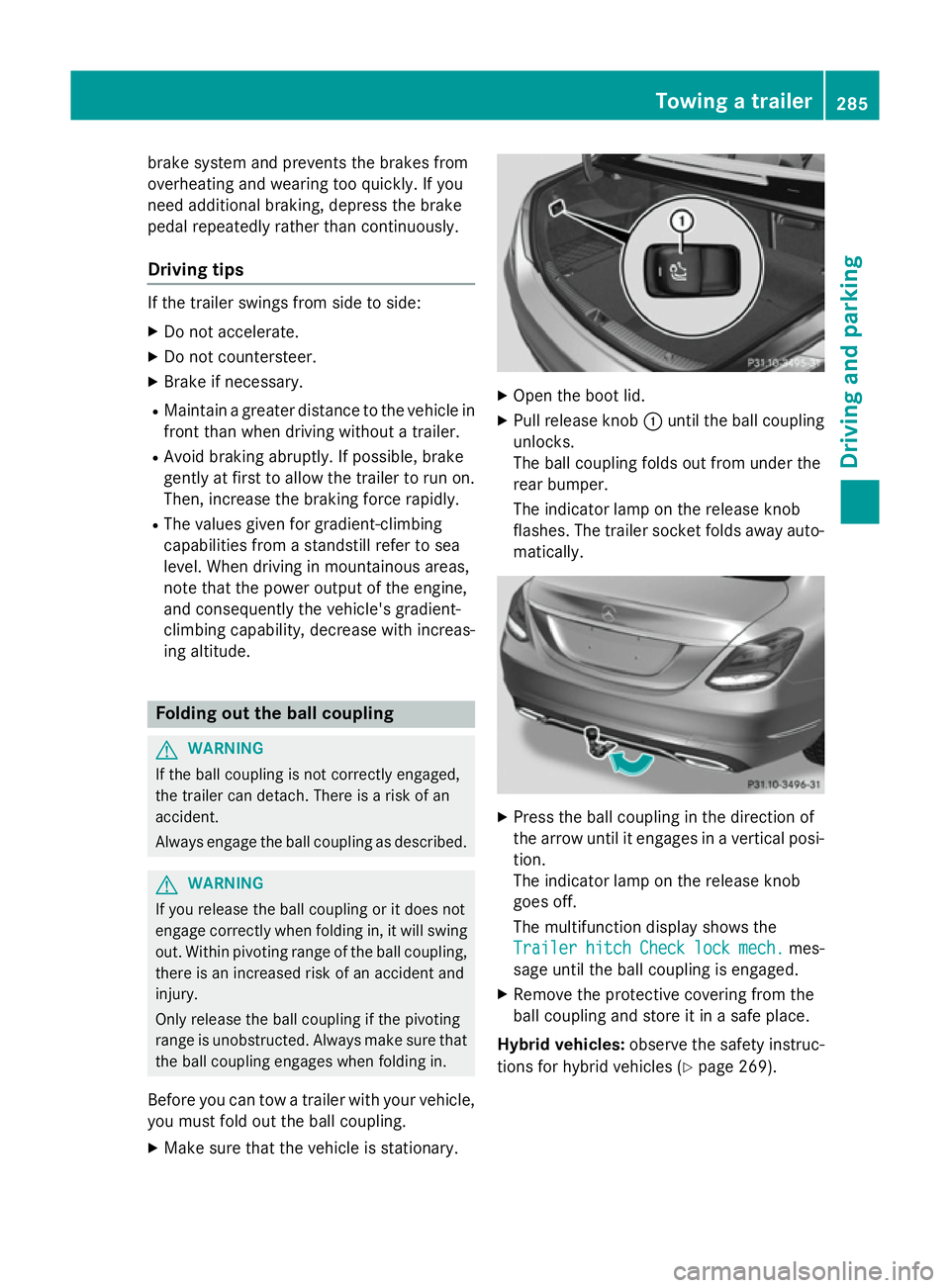
Open the boot lid.
X Pull release knob :until the ball coupling
unlocks.
The ball coupling folds out from under the
rear bumper.
The indicator lamp on the release knob
flashes. The trailer socket folds away auto- matically. X
Press the ball coupling in the direction of
the arrow until it engages in a vertical posi-
tion.
The indicator lamp on the release knob
goes off.
The multifunction display shows the
Trailer Trailer hitch
hitchCheck
Checklock
lockmech.
mech. mes-
sage until the ball coupling is engaged.
X Remove the protective covering from the
ball coupling and store it in a safe place.
Hybrid vehicles: observe the safety instruc-
tions for hybrid vehicles (Y page 269). Towing a trailer
285Driving and parking Z
Page 289 of 489
Coupling up a trailer
X Make sure that the transmission is in posi-
tion P.
X Apply the electric parking brake.
X Position the trailer horizontally behind the
vehicle.
X Couple up the trailer.
X Establish the electric connection between
the vehicle and the trailer.
X Check that the trailer lighting system is
working.
X Push the combination switch upwards/
downwards and check whether the corre-
sponding turn signal on the trailer is flash-
ing.
A connected trailer is only recognised when the electrical connection is established
correctly and when the lighting system is
working properly. The functioning of other
systems, e.g. ESP ®
, PARKTRONIC, Active
Parking Assist, Active Blind Spot Assist or
Lane Keeping Assist also depends on this. Uncoupling a trailer
G
WARNING
If you uncouple a trailer with an engaged over- run brake, you could trap your hand between
the vehicle and the trailer drawbar. This poses a risk of injury.
Do not uncouple a trailer with an engaged
overrun brake. G
WARNING
Vehicles with level control:
If you disconnect the trailer cable, the vehicle is lowered. This can cause you or others to
become trapped between the vehicle body
and tyres, or underneath the vehicle. This
poses a risk of injury.
Make sure that no-one is in the immediate
vicinity of the wheel arch or underneath the
vehicle when disconnecting the trailer cable. !
Do not disconnect a trailer with an
engaged overrun brake. Otherwise, your
vehicle could be damaged by the rebound- ing of the overrun brake.
! Remove the installed adapter cable
before folding in the ball coupling. Other-
wise, damage may occur to the rear
bumper and the adapter cable.
X Make sure that the transmission is in posi-
tion P.
X Apply the electric parking brake.
X Secure the trailer against rolling away.
X Remove the trailer cable and decouple the
trailer. Folding in the ball coupling
G
WARNING
If you release the ball coupling or it does not
engage correctly when folding in, it will swing out. Within pivoting range of the ball coupling,
there is an increased risk of an accident and
injury.
Only release the ball coupling if the pivoting
range is unobstructed. Always make sure that the ball coupling engages when folding in.
Fold the ball coupling back in if you are not
using the trailer tow hitch. X Make sure that the vehicle is stationary and
the trailer cables are disconnected.
X Place the protective covering on the ball
coupling.
X Open the boot lid. 286
Towing a trailerDriving and parking
Page 290 of 489
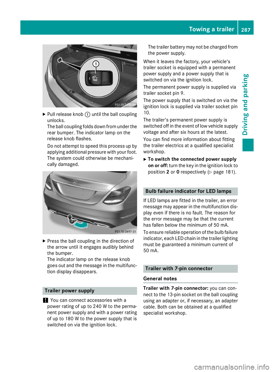
X
Pull release knob :until the ball coupling
unlocks.
The ball coupling folds down from under the rear bumper. The indicator lamp on the
release knob flashes.
Do not attempt to speed this process up by
applying additional pressure with your foot. The system could otherwise be mechani-
cally damaged. X
Press the ball coupling in the direction of
the arrow until it engages audibly behind
the bumper.
The indicator lamp on the release knob
goes out and the message in the multifunc-
tion display disappears. Trailer power supply
! You can connect accessories with a
power rating of up to 240 W to the perma-
nent power supply and with a power rating of up to 180 W to the power supply that is
switched on via the ignition lock. The trailer battery may not be charged from
the power supply.
When it leaves the factory, your vehicle's
trailer socket is equipped with a permanent
power supply and a power supply that is
switched on via the ignition lock.
The permanent power supply is supplied via
trailer socket pin 9.
The power supply that is switched on via the
ignition lock is supplied via trailer socket pin
10.
The trailer's permanent power supply is
switched off in the event of low vehicle supply
voltage and after six hours at the latest.
You can find more information about fitting
the trailer electrics at a qualified specialist
workshop.
X To switch the connected power supply
on or off: turn the key in the ignition lock to
position 2or 0respectively (Y page 181). Bulb failure indicator for LED lamps
If LED lamps are fitted in the trailer, an error
message may appear in the multifunction dis-
play even if there is no fault. The reason for
the error message may be that the current
has fallen below the minimum of 50 mA.
To ensure reliable operation of the bulb failure indicator, each LED chain in the trailer lighting
must be guaranteed a minimum current of
50 mA. Trailer with 7-pin connector
General notes Trailer with 7-pin connector:
you can con-
nect to the 13-pin socket on the ball coupling
using an adapter or, if necessary, an adapter
cable. Both can be obtained at a qualified
specialist workshop. Towing a trailer
287Driving and parking Z
Page 291 of 489
Fitting the adapter
!
Make sure that there is sufficient cable
play so that the cable cannot become
detached when cornering.
! Remove the installed adapter cable
before folding in the ball coupling. Other-
wise, damage may occur to the rear
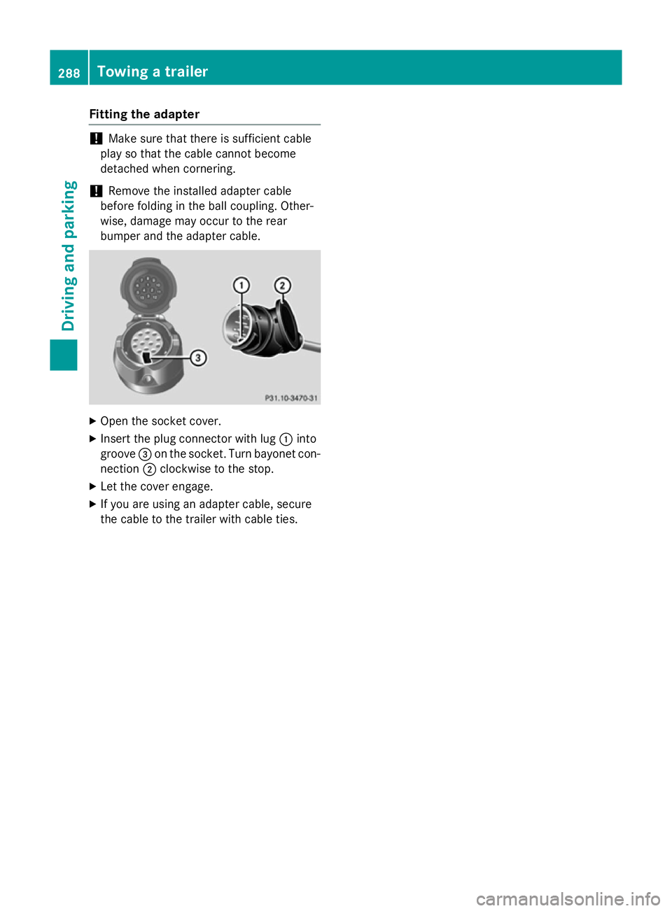
bumper and the adapter cable. X
Open the socket cover.
X Insert the plug connector with lug :into
groove =on the socket. Turn bayonet con-
nection ;clockwise to the stop.
X Let the cover engage.
X If you are using an adapter cable, secure
the cable to the trailer with cable ties. 288
Towing a trailerDriving and pa
rking
Page 292 of 489
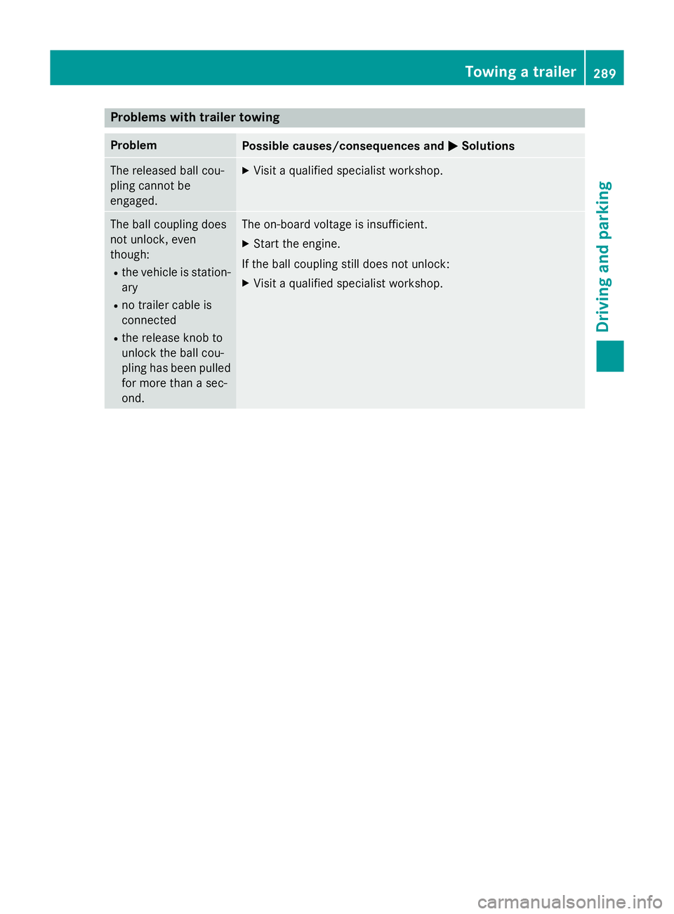
Problems with trailer towing
Problem
Possible causes/consequences and
M
MSolutions The released ball cou-
pling cannot be
engaged. X
Visit a qualified specialist workshop. The ball coupling does
not unlock, even
though:
R the vehicle is station-
ary
R no trailer cable is
connected
R the release knob to
unlock the ball cou-
pling has been pulled
for more than a sec-
ond. The on-board voltage is insufficient.
X Start the engine.
If the ball coupling still does not unlock: X Visit a qualified specialist workshop. Towing a trailer
289Driving and parking Z
Page 342 of 489
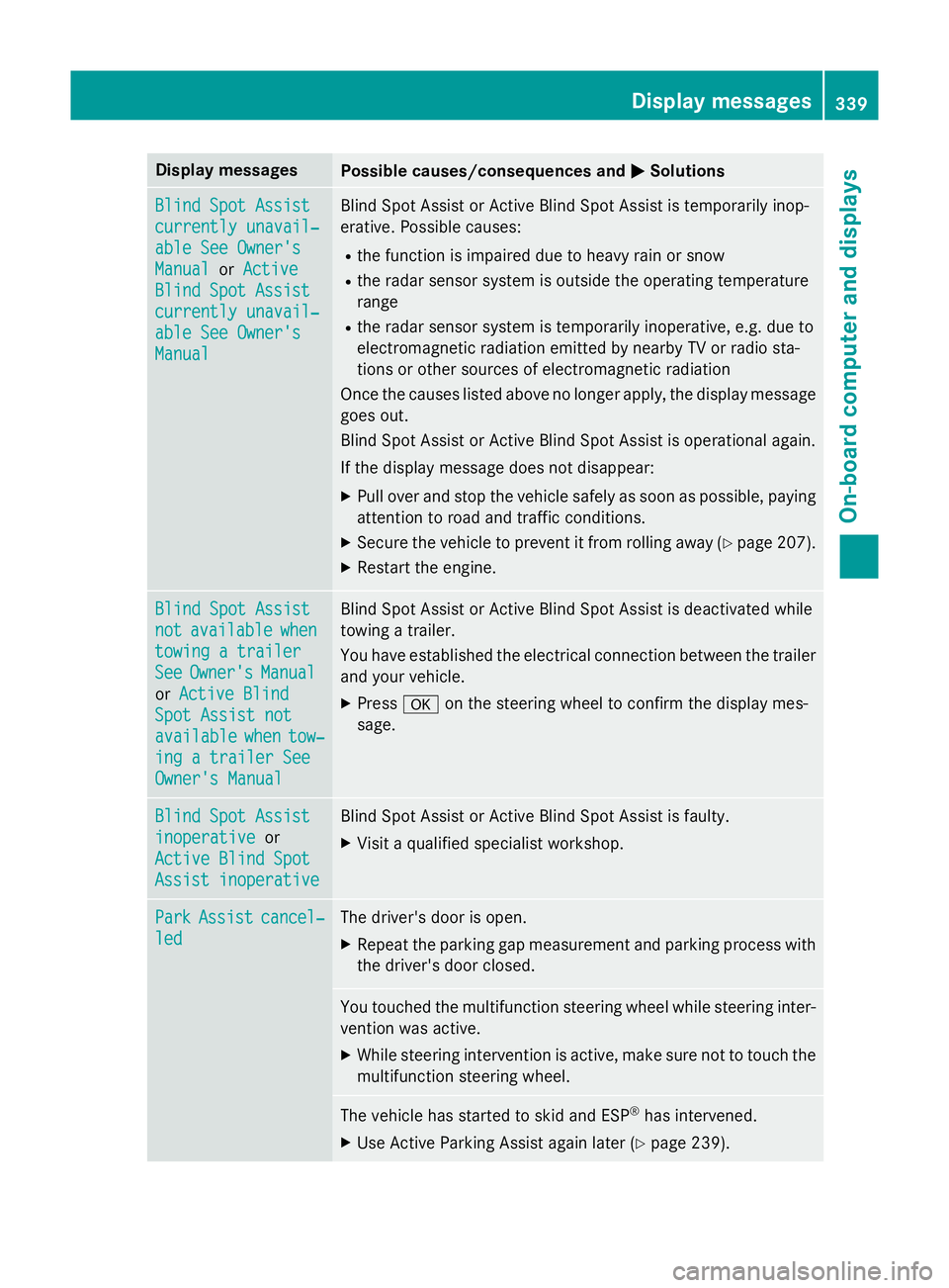
Display messages
Possible causes/consequences and
M
MSolutions Blind Spot Assist
Blind Spot Assist
currently unavail‐ currently unavail‐
able See Owner's able See Owner's
Manual Manual
orActive
Active
Blind Spot Assist
Blind Spot Assist
currently unavail‐ currently unavail‐
able See Owner's able See Owner's
Manual Manual Blind Spot Assist or Active Blind Spot Assist is temporarily inop-
erative. Possible causes:
R the function is impaired due to heavy rain or snow
R the radar sensor system is outside the operating temperature
range
R the radar sensor system is temporarily inoperative, e.g. due to
electromagnetic radiation emitted by nearby TV or radio sta-
tions or other sources of electromagnetic radiation
Once the causes listed above no longer apply, the display message goes out.
Blind Spot Assist or Active Blind Spot Assist is operational again.
If the display message does not disappear:
X Pull over and stop the vehicle safely as soon as possible, paying
attention to road and traffic conditions.
X Secure the vehicle to prevent it from rolling away (Y page 207).
X Restart the engine. Blind Spot Assist Blind Spot Assist
not not
available
available when
when
towing a trailer
towing a trailer
See See Owner's
Owner's Manual
Manual
or Active Blind
Active Blind
Spot Assist not
Spot Assist not
available available when
whentow‐
tow‐
ing a trailer See
ing a trailer See
Owner's Manual Owner's Manual Blind Spot Assist or Active Blind Spot Assist is deactivated while
towing a trailer.
You have established the electrical connection between the trailer
and your vehicle.
X Press aon the steering wheel to confirm the display mes-
sage. Blind Spot Assist Blind Spot Assist
inoperative inoperative
or
Active Blind Spot
Active Blind Spot
Assist inoperative Assist inoperative Blind Spot Assist or Active Blind Spot Assist is faulty.
X Visit a qualified specialist workshop. Park
Park
Assist
Assist cancel‐
cancel‐
led
led The driver's door is open.
X Repeat the parking gap measurement and parking process with
the driver's door closed. You touched the multifunction steering wheel while steering inter-
vention was active.
X While steering intervention is active, make sure not to touch the
multifunction steering wheel. The vehicle has started to skid and ESP
®
has intervened.
X Use Active Parking Assist again later (Y page 239). Display
messages
339On-board computer and displays Z
Page 370 of 489
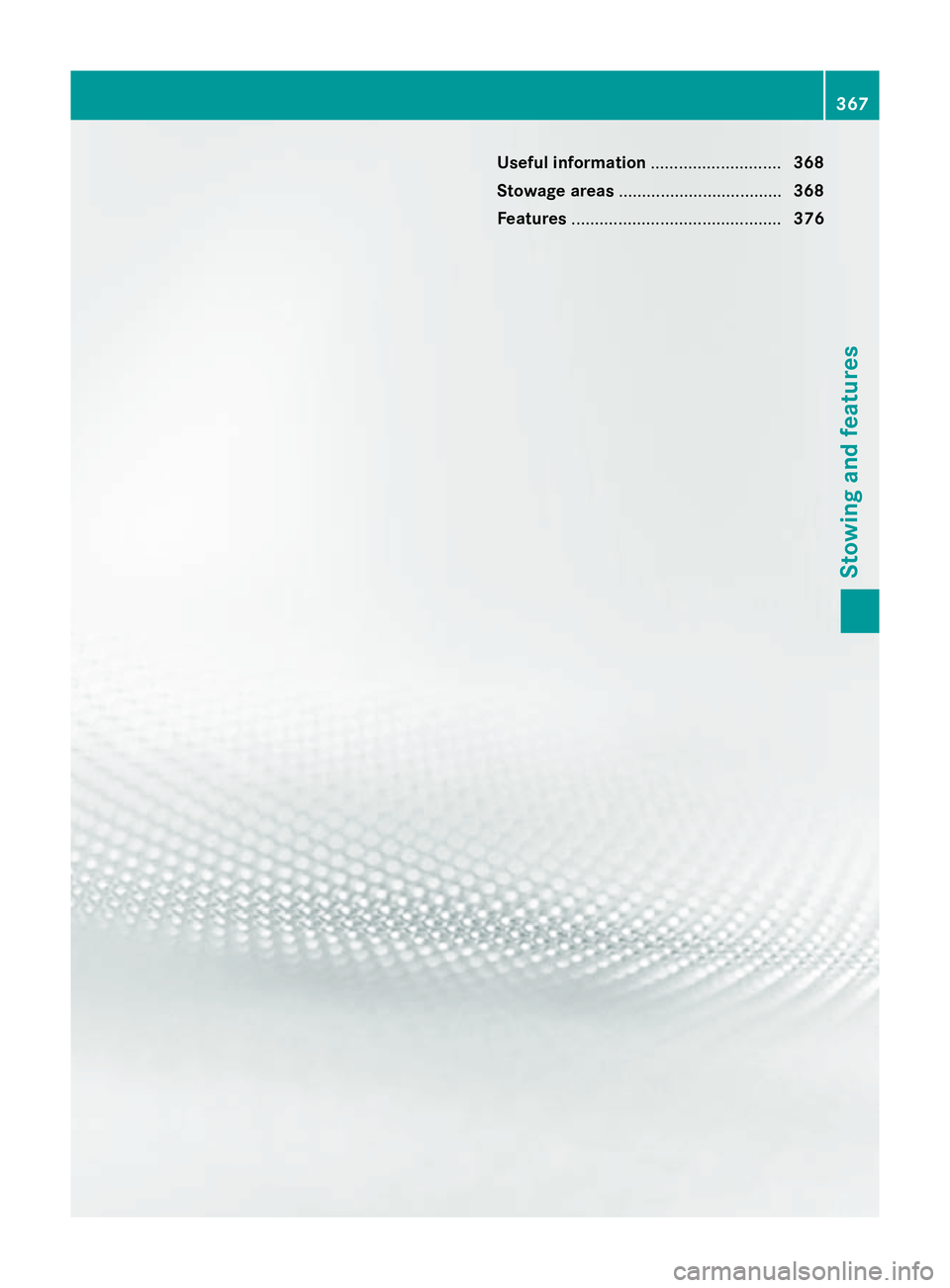
Useful information
............................368
Stowage areas ................................... 368
Features ............................................. 376 367Stowing and features
Page 371 of 489
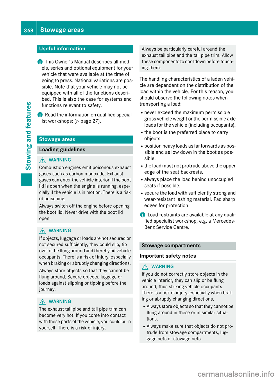
Useful information
i This Owner's Manual describes all mod-
els, series and optional equipment for your
vehicle that were available at the time of
going to press. National variations are pos- sible. Note that your vehicle may not be
equipped with all of the functions descri-
bed. This is also the case for systems and
functions relevant to safety.
i Read the information on qualified special-
ist workshops: (Y page 27). Stowage areas
Loading guidelines
G
WARNING
Combustion engines emit poisonous exhaust
gases such as carbon monoxide. Exhaust
gases can enter the vehicle interior if the boot
lid is open when the engine is running, espe-
cially if the vehicle is in motion. There is a risk of poisoning.
Always switch off the engine before opening
the boot lid. Never drive with the boot lid
open. G
WARNING
If objects, luggage or loads are not secured or not secured sufficiently, they could slip, tip
over or be flung around and thereby hit vehicle
occupants. There is a risk of injury, especially when braking or abruptly changing directions.
Always store objects so that they cannot be
flung around. Secure objects, luggage or
loads against slipping or tipping before the
journey. G
WARNING
The exhaust tail pipe and tail pipe trim can
become very hot. If you come into contact
with these parts of the vehicle, you could burn
yourself. There is a risk of injury. Always be particularly careful around the
exhaust tail pipe and the tail pipe trim. Allow
these components to cool down before touch-
ing them.
The handling characteristics of a laden vehi-
cle are dependent on the distribution of the
load within the vehicle. For this reason, you
should observe the following notes when
transporting a load:
R never exceed the maximum permissible
gross vehicle weight or the permissible axle
loads for the vehicle (including occupants).
R the boot is the preferred place to carry
objects.
R position heavy loads as far forwards as pos-
sible and as low down in the boot as pos-
sible.
R the load must not protrude above the upper
edge of the seat backrests.
R always place the load behind unoccupied
seats if possible.
R secure the load with sufficiently strong and
wear-resistant lashing material. Pad sharp
edges for protection.
i Load restraints are available at any quali-
fied specialist workshop, e.g. a Mercedes-
Benz Service Centre. Stowage compartments
Important safety notes G
WARNING
If you do not correctly store objects in the
vehicle interior, they can slip or be flung
around, thus striking vehicle occupants.
There is a risk of injury, especially when brak- ing or abruptly changing directions.
R Always store objects so that they cannot be
flung around in these or in similar situa-
tions.
R Always make sure that objects do not pro-
trude from stowage compartments, lug-
gage nets or stowage nets. 368
Stowage areasStowing and features
Page 372 of 489
R
Close lockable stowage compartments
while driving.
R Stow and secure objects that are heavy,
hard, pointy, sharp-edged, fragile or too
large in the boot.
Observe the loading guidelines (Y page 368).
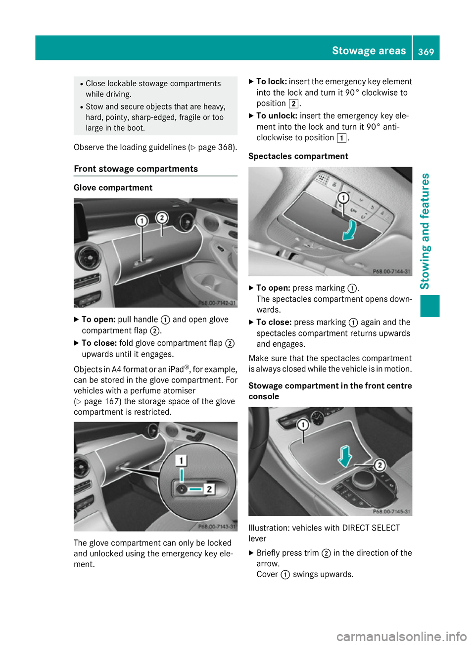
Front stowage compartments Glove compartment
X
To open: pull handle :and open glove
compartment flap ;.
X To close: fold glove compartment flap ;
upwards until it engages.
Objects in A4 format or an iPad ®
, for example,
can be stored in the glove compartment. For
vehicles with a perfume atomiser
(Y page 167) the storage space of the glove
compartment is restricted. The glove compartment can only be locked
and unlocked using the emergency key ele-
ment. X
To lock: insert the emergency key element
into the lock and turn it 90° clockwise to
position 2.
X To unlock: insert the emergency key ele-
ment into the lock and turn it 90° anti-
clockwise to position 1.
Spectacles compartment X
To open: press marking :.
The spectacles compartment opens down- wards.
X To close: press marking :again and the
spectacles compartment returns upwards
and engages.
Make sure that the spectacles compartment
is always closed while the vehicle is in motion.
Stowage compartment in the front centre
console Illustration: vehicles with DIRECT SELECT
lever
X Briefly press trim ;in the direction of the
arrow.
Cover :swings upwards. Stowage areas
369Stowing and features Z
Page 373 of 489
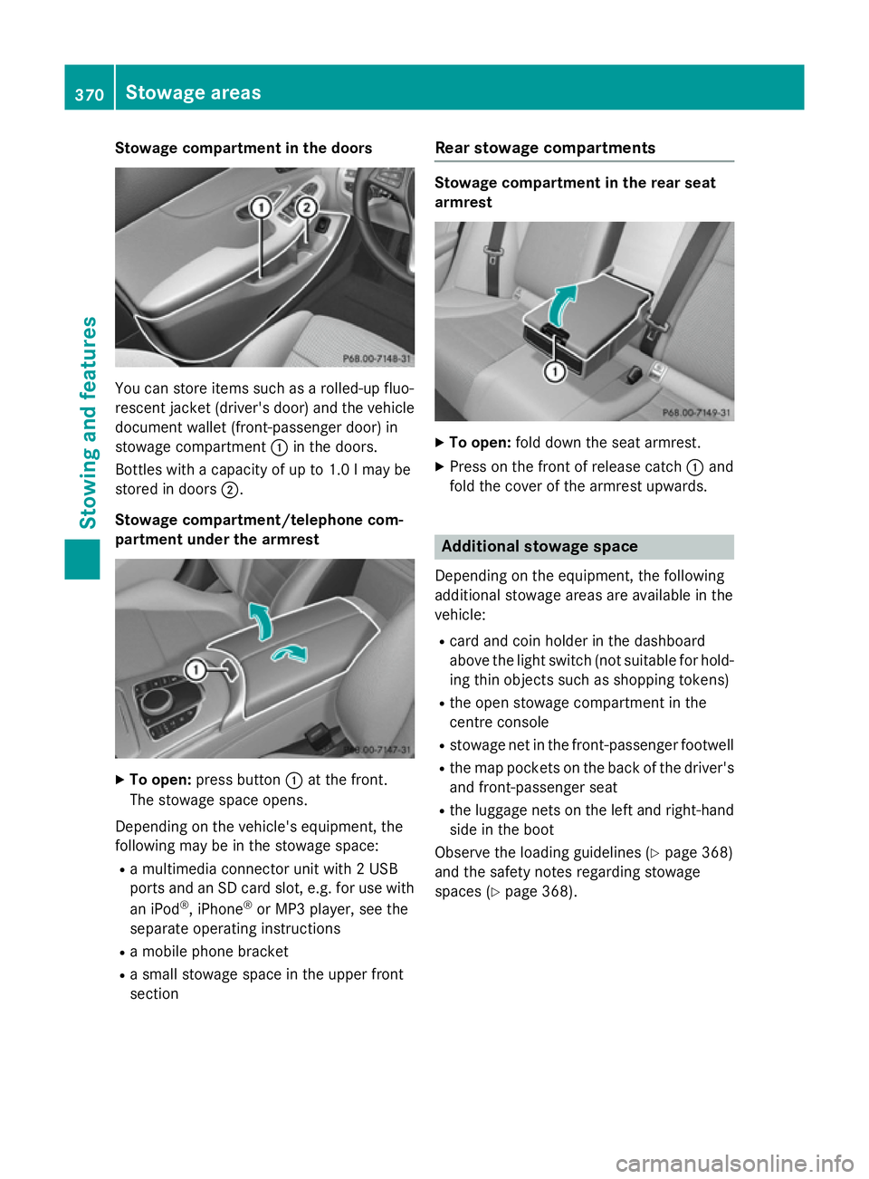
Stowage compartment in the doors
You can store items such as a rolled-up fluo-
rescent jacket (driver's door) and the vehicle document wallet (front-passenger door) in
stowage compartment :in the doors.
Bottles with a capacity of up to 1.0 lmay be
stored in doors ;.
Stowage compartment/telephone com-
partment under the armrest X
To open: press button :at the front.
The stowage space opens.
Depending on the vehicle's equipment, the
following may be in the stowage space: R a multimedia connector unit with 2 USB
ports and an SD card slot, e.g. for use with
an iPod ®
, iPhone ®
or MP3 player, see the
separate operating instructions
R a mobile phone bracket
R a small stowage space in the upper front
section Rear stowage compartments Stowage compartment in the rear seat
armrest
X
To open: fold down the seat armrest.
X Press on the front of release catch :and
fold the cover of the armrest upwards. Additional stowage space
Depending on the equipment, the following
additional stowage areas are available in the
vehicle:
R card and coin holder in the dashboard
above the light switch (not suitable for hold-
ing thin objects such as shopping tokens)
R the open stowage compartment in the
centre console
R stowage net in the front-passenger footwell
R the map pockets on the back of the driver's
and front-passenger seat
R the luggage nets on the left and right-hand
side in the boot
Observe the loading guidelines (Y page 368)
and the safety notes regarding stowage
spaces (Y page 368). 370
Stowage areasStowing and features