automatic transmission MERCEDES-BENZ C-CLASS SALOON 2014 Repair Manual
[x] Cancel search | Manufacturer: MERCEDES-BENZ, Model Year: 2014, Model line: C-CLASS SALOON, Model: MERCEDES-BENZ C-CLASS SALOON 2014Pages: 489, PDF Size: 14.88 MB
Page 284 of 489
Parking
X Apply the electric parking brake.
The red !indicator lamp in the instru-
ment cluster lights up.
X Use the DIRECT SELECT lever to shift the
automatic transmission to P.
X Switch the ignition off.
The READY indicator in the instrument clus-
ter goes out.
Further information on parking and switching off the internal combustion engine
(Y page 208). Hybrid operation
281Driving and parking Z
Page 298 of 489
8 R
Mute ó
Switches on LINGUATRONIC, see
the separate operating instructions
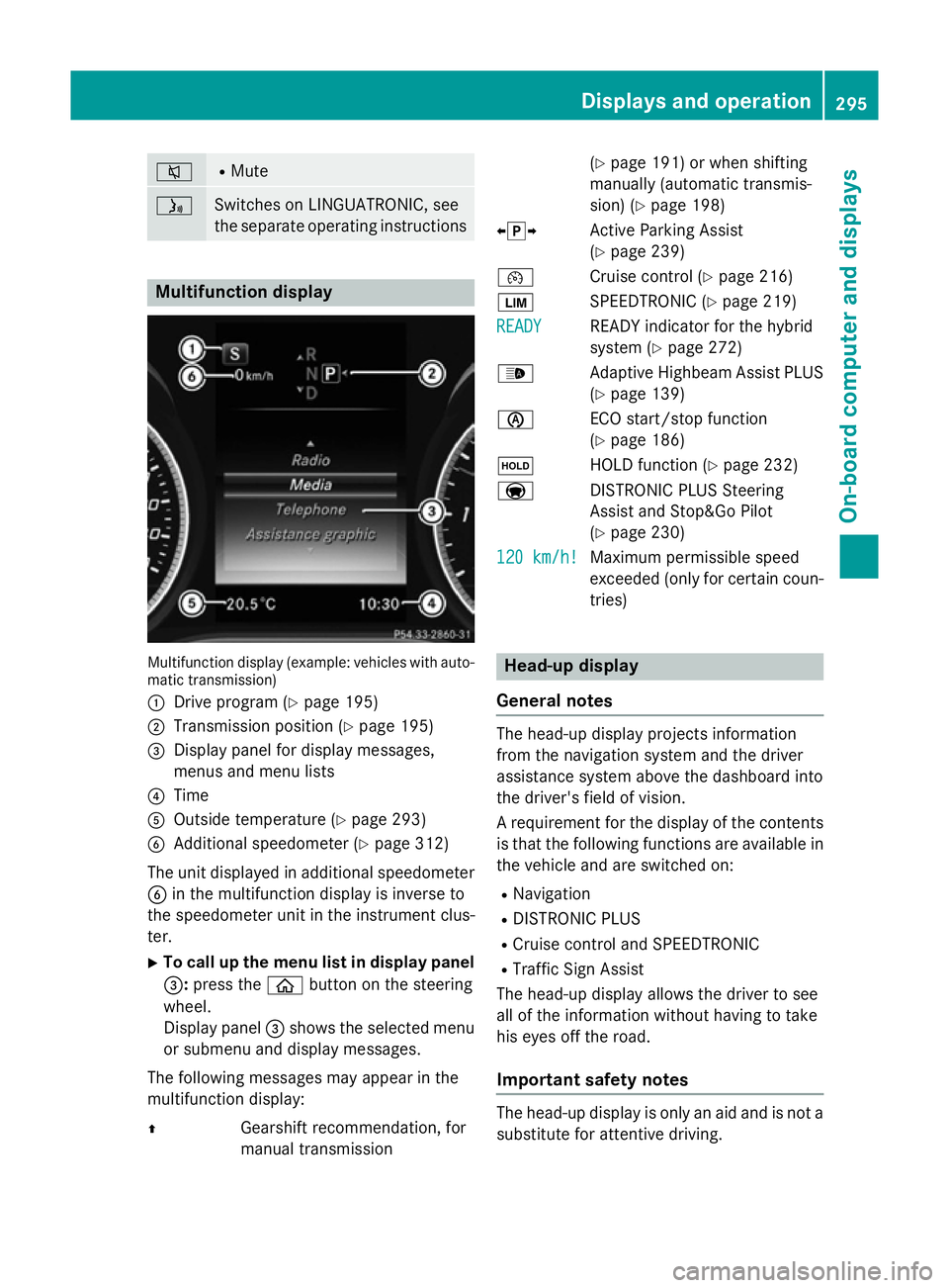
Multifunction display
Multifunction display (example: vehicles with auto-
matic transmission)
: Drive program (Y page 195)
; Transmission position (Y page 195)
= Display panel for display messages,
menus and menu lists
? Time
A Outside temperature (Y page 293)
B Additional speedometer (Y page 312)
The unit displayed in additional speedometer
B in the multifunction display is inverse to
the speedometer unit in the instrument clus-
ter.
X To call up the menu list in display panel
=: press the òbutton on the steering
wheel.
Display panel =shows the selected menu
or submenu and display messages.
The following messages may appear in the
multifunction display:
Z Gearshift recommendation, for
manual transmission (Y
page 191) or when shifting
manually (automatic transmis-
sion) (Y page 198)
XjY Active Parking Assist
(Y page 239)
¯ Cruise control (Y page 216)
È SPEEDTRONIC (Y page 219)
READY
READY READY indicator for the hybrid
system (Y
page 272)
_ Adaptive Highbeam Assist PLUS
(Y page 139)
è ECO start/stop function
(Ypage 186)
ë HOLD function (Y page 232)
a DISTRONIC PLUS Steering
Assist and Stop&Go Pilot
(Ypage 230)
120 km/h! 120 km/h! Maximum permissible speed
exceeded (only for certain coun-
tries) Head-up display
General notes The head-up display projects information
from the navigation system and the driver
assistance system above the dashboard into
the driver's field of vision.
A requirement for the display of the contents
is that the following functions are available in the vehicle and are switched on:
R Navigation
R DISTRONIC PLUS
R Cruise control and SPEEDTRONIC
R Traffic Sign Assist
The head-up display allows the driver to see
all of the information without having to take
his eyes off the road.
Important safety notes The head-up display is only an aid and is not a
substitute for attentive driving. Displays and operation
295On-board computer and displays Z
Page 322 of 489
Display messages
Possible causes/consequences and
M
MSolutions The red
!indicator lamp flashes and a warning tone sounds.
You are making an emergency stop using the electric parking
brake (Y page 209). !
Parking brake See Parking brake See
Owner's Manual Owner's Manual The yellow
!warning lamp lights up.
The electric parking brake is malfunctioning.
To apply:
X Switch the ignition off.
X Press the electric parking brake handle for at least ten seconds.
X Vehicles with manual transmission: engage first gear.
X Vehicles with automatic transmission: shift the transmission
to P.
X Consult a qualified specialist workshop. The yellow
!warning lamp and the red !indicator lamp are
lit.
The electric parking brake is malfunctioning.
To release:
X Switch off the ignition and turn it back on.
X Release the electric parking brake manually.
or X Release the electric parking brake automatically (Y page 209).
If the electric parking brake still cannot be released: X Do not drive on.
X Consult a qualified specialist workshop. Display
messages
319On-board computer and displays Z
Page 323 of 489
Display messages
Possible causes/consequences and
M
MSolutions The red
!indicator lamp flashes and the yellow !warning
lamp is lit.
The electric parking brake is malfunctioning.
To release:
X Switch off the ignition and turn it back on.
X Release the electric parking brake manually.
To apply:
X Switch off the ignition and turn it back on.
X Apply the electric parking brake manually.
If the red !indicator lamp continues to flash:
X Do not drive on.
X Secure the vehicle against rolling away (Y page 439).
X Vehicles with manual transmission: engage first gear.
X Vehicles with automatic transmission: shift the transmission
to P.
X Turn the front wheels towards the kerb.
X Consult a qualified specialist workshop. The yellow
!warning lamp lights up. The red !indicator
lamp flashes for about ten seconds after the electric parking brake
has been applied or released. It then goes out or remains lit.
The electric parking brake is malfunctioning.
X Switch off the ignition and turn it back on.
X Apply the electric parking brake.
If it is not possible to apply the electric parking brake:
X Vehicles with manual transmission: engage first gear.
X Vehicles with automatic transmission: shift the transmission
to P.
X Consult a qualified specialist workshop.
If it is not possible to release the electric parking brake manually:
X Release the electric parking brake automatically (Y page 209).
If the electric parking brake still cannot be released: X Consult a qualified specialist workshop. 320
Display
messagesOn-board computer and displays
Page 324 of 489
Display messages
Possible causes/consequences and
M
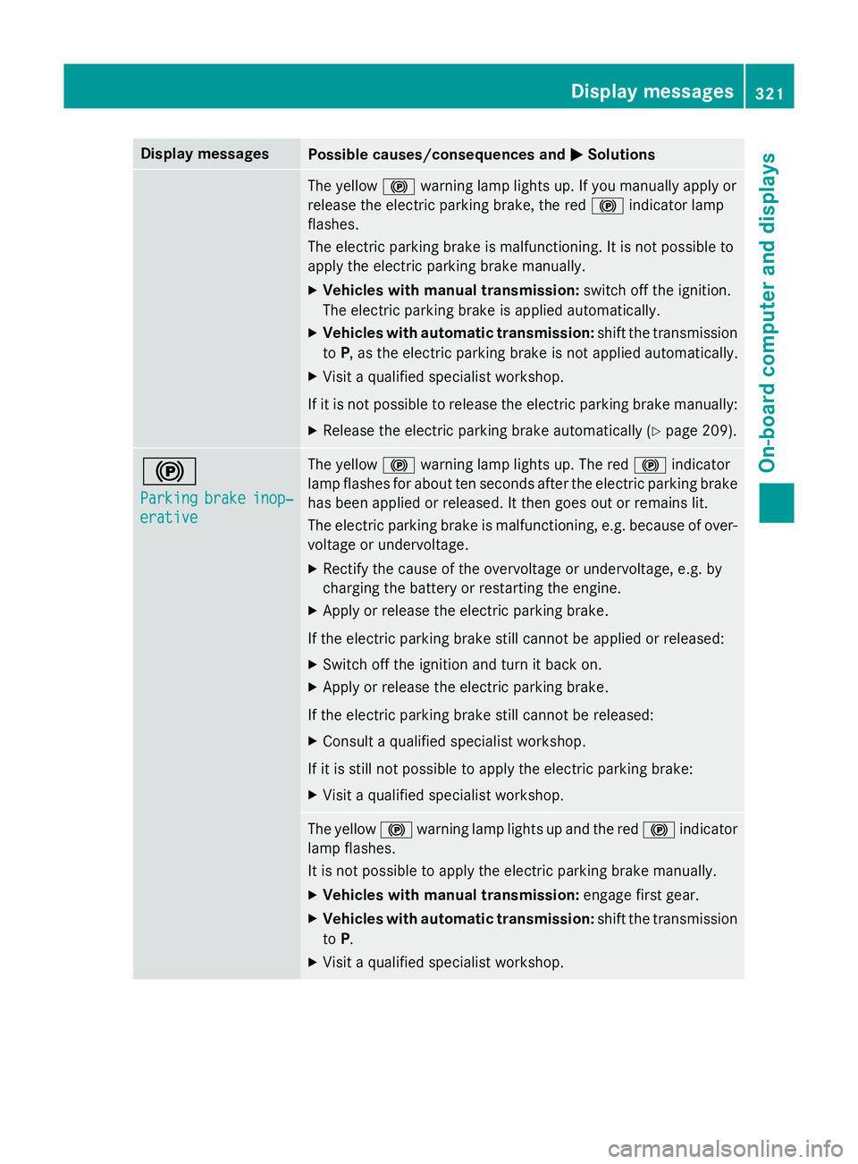
MSolutions The yellow
!warning lamp lights up. If you manually apply or
release the electric parking brake, the red !indicator lamp
flashes.
The electric parking brake is malfunctioning. It is not possible to
apply the electric parking brake manually.
X Vehicles with manual transmission: switch off the ignition.
The electric parking brake is applied automatically.
X Vehicles with automatic transmission: shift the transmission
to P, as the electric parking brake is not applied automatically.
X Visit a qualified specialist workshop.
If it is not possible to release the electric parking brake manually: X Release the electric parking brake automatically (Y page 209).!
Parking Parking
brake
brakeinop‐
inop‐
erative
erative The yellow
!warning lamp lights up. The red !indicator
lamp flashes for about ten seconds after the electric parking brake
has been applied or released. It then goes out or remains lit.
The electric parking brake is malfunctioning, e.g. because of over- voltage or undervoltage.
X Rectify the cause of the overvoltage or undervoltage, e.g. by
charging the battery or restarting the engine.
X Apply or release the electric parking brake.
If the electric parking brake still cannot be applied or released: X Switch off the ignition and turn it back on.
X Apply or release the electric parking brake.
If the electric parking brake still cannot be released: X Consult a qualified specialist workshop.
If it is still not possible to apply the electric parking brake: X Visit a qualified specialist workshop. The yellow
!warning lamp lights up and the red !indicator
lamp flashes.
It is not possible to apply the electric parking brake manually.
X Vehicles with manual transmission: engage first gear.
X Vehicles with automatic transmission: shift the transmission
to P.
X Visit a qualified specialist workshop. Display
messages
321On-board computer and displays Z
Page 348 of 489

Display messages
Possible causes/consequences and
M
MSolutions Tyre press. moni‐
Tyre press. moni‐
tor currently tor currently
unavailable unavailable Due to a source of radio interference, no signals can be received
from the wheel sensors. The tyre pressure monitor is temporarily
malfunctioning.
X Drive on.
The tyre pressure monitor restarts automatically as soon as the
cause has been rectified. Wheel sensor(s) Wheel sensor(s)
missing missing There is no signal from the tyre pressure sensor of one or several
wheels. The pressure of the affected tyre is not displayed in the
multifunction display.
X Have the faulty tyre pressure sensor replaced at a qualified spe-
cialist workshop. Tyre press. moni‐ Tyre press. moni‐
tor tor
inoperative
inoperative No
No
wheel sensors
wheel sensors The wheels fitted do not have suitable tyre pressure sensors. The
tyre pressure monitor is deactivated.
X Fit wheels with suitable tyre pressure sensors.
The tyre pressure monitor is activated automatically after driv-
ing for a few minutes. Tyre press. moni‐ Tyre press. moni‐
tor inoperative tor inoperative The tyre pressure monitor is faulty.
X Visit a qualified specialist workshop. Vehicle
Display messages
Possible causes/consequences and
M
MSolutions To start engine,
To start engine,
shift to either P shift to either P
or N or N You have attempted to start the engine with the transmission in
position
Ror D.
X Shift the transmission to position Por N. Auxiliary battery Auxiliary battery
malfunction malfunction The auxiliary battery for the transmission is no longer being
charged.
X Visit a qualified specialist workshop. Apply brake to Apply brake to
deselect Park (P) deselect Park (P)
position position You have attempted to move the transmission selector lever to
position
D,Ror Nwithout depressing the brake pedal.
X Depress the brake pedal. Display
messages
345On-board computer and displays Z
Page 358 of 489
Warning/
indicator
lamp
N N
Signal type
Possible causes/consequences and M
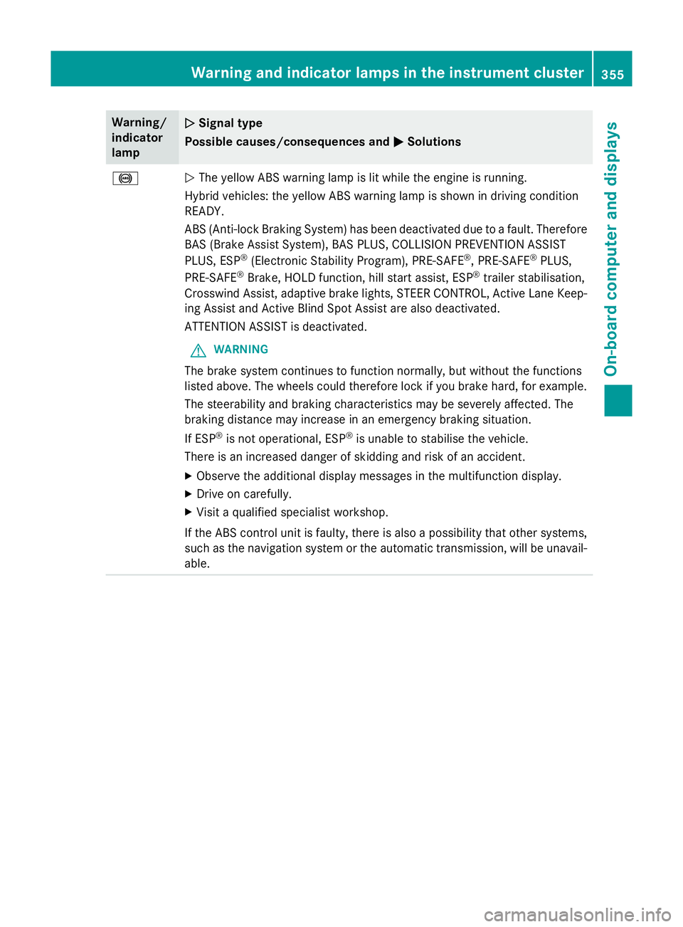
MSolutions !
N
The yellow ABS warning lamp is lit while the engine is running.
Hybrid vehicles: the yellow ABS warning lamp is shown in driving condition
READY.
ABS (Anti-lock Braking System) has been deactivated due to a fault. Therefore BAS (Brake Assist System), BAS PLUS, COLLISION PREVENTION ASSIST
PLUS, ESP ®
(Electronic Stability Program), PRE‑SAFE ®
, PRE‑ SAFE®
PLUS,
PRE‑ SAFE ®
Brake, HOLD function, hill start assist, ESP ®
trailer stabilisation,
Crosswind Assist, adaptive brake lights, STEER CONTROL, Active Lane Keep-
ing Assist and Active Blind Spot Assist are also deactivated.
ATTENTION ASSIST is deactivated.
G WARNING
The brake system continues to function normally, but without the functions
listed above. The wheels could therefore lock if you brake hard, for example.
The steerability and braking characteristics may be severely affected. The
braking distance may increase in an emergency braking situation.
If ESP ®
is not operational, ESP ®
is unable to stabilise the vehicle.
There is an increased danger of skidding and risk of an accident.
X Observe the additional display messages in the multifunction display.
X Drive on carefully.
X Visit a qualified specialist workshop.
If the ABS control unit is faulty, there is also a possibility that other systems,
such as the navigation system or the automatic transmission, will be unavail- able. Warning and indicator lamps in the instrument cluster
355On-board computer and displays Z
Page 380 of 489
!
Only use the cup holders for containers of
the right size and which have lids. The
drinks could otherwise spill. G
WARNING
If you do not correctly store objects in the
vehicle interior, they can slip or be flung
around, thus striking vehicle occupants.
There is a risk of injury, especially when brak- ing or abruptly changing directions.
R Always store objects so that they cannot be
flung around in these or in similar situa-
tions.
R Always make sure that objects do not pro-
trude from stowage compartments, lug-
gage nets or stowage nets.
R Close lockable stowage compartments
while driving.
R Stow and secure objects that are heavy,
hard, pointy, sharp-edged, fragile or too
large in the boot.
Observe the loading guidelines (Y page 368).
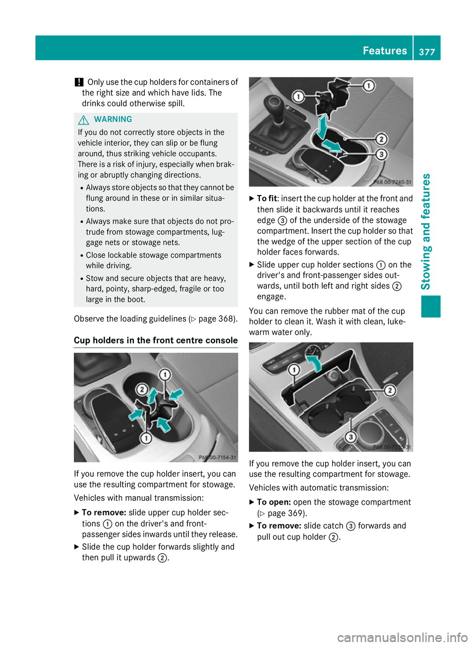
Cup holders in the front centre console If you remove the cup holder insert, you can
use the resulting compartment for stowage.
Vehicles with manual transmission:
X To remove: slide upper cup holder sec-
tions :on the driver's and front-
passenger sides inwards until they release.
X Slide the cup holder forwards slightly and
then pull it upwards ;. X
To fit: insert the cup holder at the front and
then slide it backwards until it reaches
edge =of the underside of the stowage
compartment. Insert the cup holder so that
the wedge of the upper section of the cup
holder faces forwards.
X Slide upper cup holder sections :on the
driver's and front-passenger sides out-
wards, until both left and right sides ;
engage.
You can remove the rubber mat of the cup
holder to clean it. Wash it with clean, luke-
warm water only. If you remove the cup holder insert, you can
use the resulting compartment for stowage.
Vehicles with automatic transmission:
X
To open: open the stowage compartment
(Y page 369).
X To remove: slide catch=forwards and
pull out cup holder ;. Features
377Stowing and features Z
Page 383 of 489
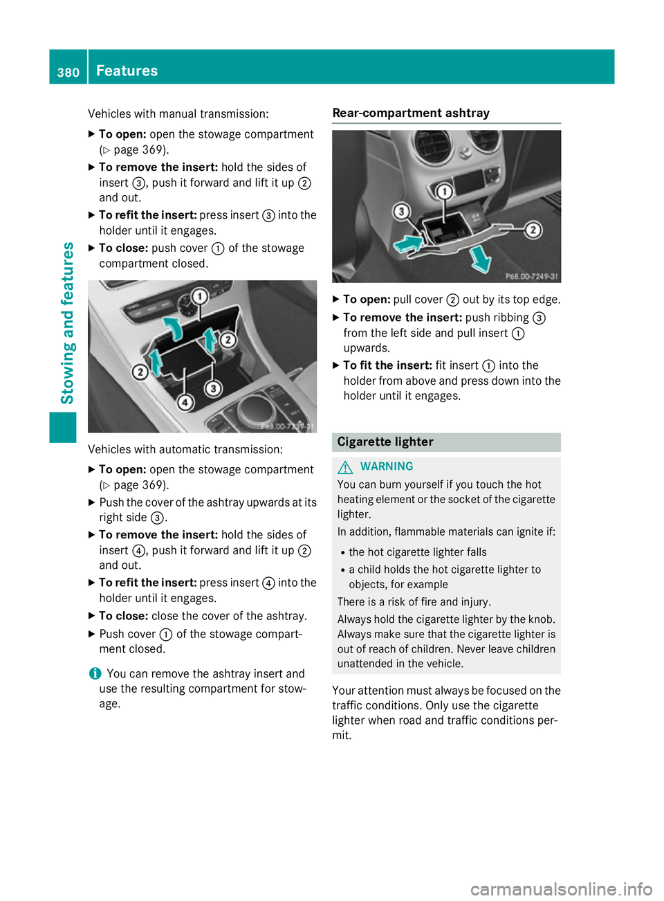
Vehicles with manual transmission:
X
To open: open the stowage compartment
(Y page 369).
X To remove the insert: hold the sides of
insert =, push it forward and lift it up ;
and out.
X To refit the insert: press insert=into the
holder until it engages.
X To close: push cover :of the stowage
compartment closed. Vehicles with automatic transmission:
X
To open: open the stowage compartment
(Y page 369).
X Push the cover of the ashtray upwards at its
right side =.
X To remove the insert: hold the sides of
insert ?, push it forward and lift it up ;
and out.
X To refit the insert: press insert?into the
holder until it engages.
X To close: close the cover of the ashtray.
X Push cover :of the stowage compart-
ment closed.
i You can remove the ashtray insert and
use the resulting compartment for stow-
age. Rear-compartment ashtray X
To open: pull cover ;out by its top edge.
X To remove the insert: push ribbing=
from the left side and pull insert :
upwards.
X To fit the insert: fit insert:into the
holder from above and press down into the
holder until it engages. Cigarette lighter
G
WARNING
You can burn yourself if you touch the hot
heating element or the socket of the cigarette lighter.
In addition, flammable materials can ignite if:
R the hot cigarette lighter falls
R a child holds the hot cigarette lighter to
objects, for example
There is a risk of fire and injury.
Always hold the cigarette lighter by the knob.
Always make sure that the cigarette lighter is
out of reach of children. Never leave children unattended in the vehicle.
Your attention must always be focused on the traffic conditions. Only use the cigarette
lighter when road and traffic conditions per-
mit. 380
FeaturesStowing and features
Page 384 of 489
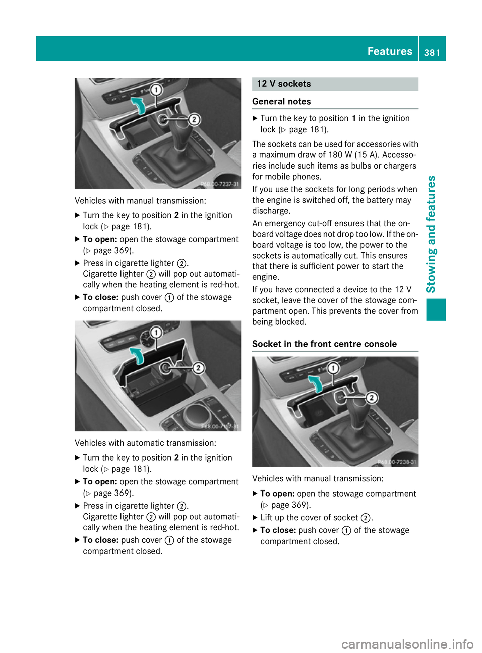
Vehicles with manual transmission:
X
Turn the key to position 2in the ignition
lock (Y page 181).
X To open: open the stowage compartment
(Y page 369).
X Press in cigarette lighter ;.
Cigarette lighter ;will pop out automati-
cally when the heating element is red-hot.
X To close: push cover :of the stowage
compartment closed. Vehicles with automatic transmission:
X
Turn the key to position 2in the ignition
lock (Y page 181).
X To open: open the stowage compartment
(Y page 369).
X Press in cigarette lighter ;.
Cigarette lighter ;will pop out automati-
cally when the heating element is red-hot.
X To close: push cover :of the stowage
compartment closed. 12 V sockets
General notes X
Turn the key to position 1in the ignition
lock (Y page 181).
The sockets can be used for accessories with a maximum draw of 180 W(15 A). Accesso-
ries include such items as bulbs or chargers
for mobile phones.
If you use the sockets for long periods when
the engine is switched off, the battery may
discharge.
An emergency cut-off ensures that the on-
board voltage does not drop too low. If the on-
board voltage is too low, the power to the
sockets is automatically cut. This ensures
that there is sufficient power to start the
engine.
If you have connected a device to the 12 V
socket, leave the cover of the stowage com-
partment open. This prevents the cover from
being blocked.
Socket in the front cent re console Vehicles with manual transmission:
X To open: open the stowage compartment
(Y page 369).
X Lift up the cover of socket ;.
X To close: push cover :of the stowage
compartment closed. Features
381Stowing an d features Z