towing MERCEDES-BENZ C-Class SEDAN 2016 W205 Owner's Manual
[x] Cancel search | Manufacturer: MERCEDES-BENZ, Model Year: 2016, Model line: C-Class SEDAN, Model: MERCEDES-BENZ C-Class SEDAN 2016 W205Pages: 398, PDF Size: 9.57 MB
Page 7 of 398
Battery (SmartKey)Checking .......................................... 84
Important safety notes .................... 84
Replacing ......................................... 84
Battery (vehicle)
Charging ........................................ 350
Display message ............................ 269
Important safety notes .................. 347
Jump starting ................................. 352
Belt
see Seat belts
Blind Spot Assist
Activating/deactivating (on-
board computer) ............................ 248
Display message ............................ 276
Notes/function .............................. 216
see Active Blind Spot Assist
Bluetooth
®
Connecting another mobile
phone ............................................ 306
Searching for a mobile phone ........ 306
see also Digital Operator's Man-
ual .................................................. 298
Telephony ...................................... 305
Box (trunk) ......................................... 314
Brake Assist
see BAS (Brake Assist System)
Brake fluid
Display message ............................ 261
Notes ............................................. 392
Brake force distribution
see EBD (electronic brake force
distribution)
Brake pedal
Pedal resistance/pedal travel .......... 45
Brakes
ABS .................................................. 68
Adaptive Brake Assist ...................... 72
BAS .................................................. 68
BAS PLUS with Cross-Traffic
Assist ............................................... 69
Brake fluid (notes) ......................... 392
Display message ............................ 256
EBD .................................................. 76
High-performance brake system .... 183
Hill start assist ............................... 150
HOLD function ............................... 194
Important safety notes .................. 182 Maintenance .................................. 183
Parking brake ................................ 178
RBS warning lamp .......................... 288
Recuperative Brake System ............. 45
Riding tips ...................................... 182
Warning lamp ................................. 288
Breakdown
Where will I find...? ........................ 342
see Flat tire
see Towing away
Brightness control (instrument
cluster lighting) ................................... 35
Buttons on the steering wheel ......... 236
C
California
Important notice for retail cus-
tomers and lessees .......................... 28
Calling up a malfunction
see Display messages
Calling up the climate control bar
Multimedia system ........................ 302
Calling up the climate control
menu
Multimedia system ........................ 302
Car
see Vehicle
Care
360° camera ................................. 339
AIRPANEL ...................................... 339
Car wash ........................................ 335
Carpets .......................................... 341
Display ........................................... 340
Exhaust pipe .................................. 340
Exterior lights ................................ 338
Gear or selector lever .................... 340
General notes ................................ 335
Interior ........................................... 340
Matte finish ................................... 337
Paint .............................................. 337
Plastic trim .................................... 340
Power washer ................................ 336
Rear view camera .......................... 339
Roof lining ...................................... 341
Seat belt ........................................ 341
Seat cover ..................................... 341
Sensors ......................................... 339
Index5
Page 24 of 398
Sidewall (definition) ....................... 379
Snow chains .................................. 363
Speed rating (definition) ................ 378
Storing ........................................... 380
Structure and characteristics
(definition) ..................................... 377
Summer tires in winter .................. 362
Temperature .................................. 374
TIN (Tire Identification Number)
(definition) ..................................... 379
Tire bead (definition) ...................... 379
Tire pressure (definition) ................ 379
Tire pressures (recommended) ...... 378
Tire size (data) ............................... 384
Tire size designation, load-bearing
capacity, speed rating .................... 374
Tire tread ....................................... 361
Tire tread (definition) ..................... 379
Total load limit (definition) ............. 379
Traction ......................................... 373
Traction (definition) ....................... 379
Tread wear ..................................... 373
Uniform Tire Quality Grading
Standards ...................................... 373
Uniform Tire Quality Grading
Standards (definition) .................... 378
Wear indicator (definition) ............. 379
Wheel and tire combination ........... 384
Wheel rim (definition) .................... 378
see Flat tire
Top Tether ............................................ 64
Touchpad
Changing the station/music
track .............................................. 301
Character suggestions ................... 300
Deleting characters ....................... 300
Entering a space ............................ 300
Entering characters ....................... 300
Gesture control .............................. 300
Handwriting recognition ................ 300
Operating the touchpad ................. 300
Overview ........................................ 300
Quick access for Audio .................. 301
Switching ....................................... 300
Switching input line ....................... 300
Tow-starting
Emergency engine starting ............ 357
Important safety notes .................. 354 Towing a trailer
ESP®(Electronic Stability Pro-
gram) ............................................... 76
Towing away
Important safety guidelines ........... 354
Insta
lling the towing eye ................ 355
Notes for 4MATIC vehicles ............ 356
Removing the towing eye ............... 355
Transporting the vehicle ................ 356
With both axles on the ground ....... 356
With the rear axle raised ................ 355
Towing eye ......................................... 343
Traffic reports
see also Digital Operator's Man-
ual .................................................. 298
Traffic Sign Assist
Display message ............................ 277
Function/notes ............................. 215
Important safety notes .................. 215
Instrument cluster display ............. 216
Transfer case ..................................... 164
Transmission
see Automatic transmission
Transmission position display ......... 157
Transmission position display
(DIRECT SELECT lever) ...................... 157
Transporting the vehicle .................. 356
Trim pieces (cleaning instruc-
tions) .................................................. 340
Trip computer (on-board com-
puter) .................................................. 240
Trip odometer
Calling up ....................................... 239
Resetting (on-board computer) ...... 241
Trunk
Important safety notes .................... 89
Locking separately ........................... 94
Opening/closing (automatically
from inside) ...................................... 93
Opening/closing (automatically
from outside) ................................... 91
Opening/closing (from outside,
HANDS-FREE ACCESS) .................... 92
Opening/closing (manually from
outside) ............................................ 90
Trunk lid
Display message ............................ 283
22Index
Page 25 of 398
Obstacle recognition ........................ 90
Opening dimensions ......................394
Opening/closing .............................. 89
Trunk load (maximum) ......................394
Turn signals
Changing bulbs (front) ................... 124
Changing bulbs (rear) .................... 124
Display message ............................ 267
Switching on/off ........................... 119
Two-way radio
Frequencies ................................... 386
Installation ..................................... 386
Transmission output (maximum) .... 386
Type identification plate
see Vehicle identification plate
U
UnlockingEmergency unlocking ....................... 89
From inside the vehicle (central
unlocking button) .............................8 8
USB devices
Connecting to the Media Inter-
face .............................................. .307
V
Vanity mirror (in the sun visor) ........317
Vehicle
Correct use ...................................... 32
Data acquisition ............................... 32
Display message ............................ 282
Equipment ....................................... 28
Individual settings .......................... 247
Limited Warranty .............................3 2
Loading .......................................... 370
Locking (in an emergency) ............... 89
Locking (SmartKey) .......................... 81
Lowering ........................................ 384
Maintenance .................................... 29
Operating safety .............................. 30
Parking .......................................... 177
Parking for a long period ................ 179
Pulling away ................................... 149
Raising ........................................... 381
Reporting problems ......................... 32
Securing from rolling away ............ 380
Towing away .................................. 354 Transporting .................................. 356
Unlocking (in an emergency) ........... 89
Unlocking (SmartKey) ...................... 81
Vehicle data ................................... 394
Vehicle data
Roof load (maximum) ..................... 394
Trunk load (maximum) ................... 394
Vehicle dimensions ........................... 394
Vehicle emergency locking ................ 89
Vehicle identification number
see VIN
Vehicle identification plate .............. 387
Vehicle level
AIRMATIC ...................................... 197
Display message ............................ 275
Vehicle tool kit .................................. 343
Video
Operating the DVD ......................... 244
see also Digital Operator's Man-
ual .................................................. 298
VIN
Seat ............................................... 388
Type plate ...................................... 387
Voice Control System
see Separate operating instructions
W
WarningStickers ........................................... 44
Warning and indicator lamps
ABS ................................................ 289
Brakes ........................................... 288
Check Engine ................................. 293
Coolant .......................................... 293
Distance warning ........................... 295
ESP
®.............................................. 290
ESP®OFF ....................................... 291
Fuel tank ........................................ 293
General notes ................................ 286
Hybrid drive system ....................... 288
Overview .......................................... 36
Parking brake ................................ 292
PASSENGER AIR BAG ...................... 47
RBS (Recuperative Brake Sys-
tem) ............................................... 288
Reserve fuel ................................... 293
Restraint system ............................ 292
Index23
Page 46 of 398
Hybrid vehicles
General notes
Hybrid technology combines a fuel efficient
internal combustion engine with a powerful
electric motor.
Important safety notes
Danger of electric shock
GDANGER
The vehicle's high-voltage electrical system is under high voltage. If you modify components
in the vehicle's high-voltage electrical system
or touch damaged components, you may be
electrocuted. The components in the vehi-
cle's high-voltage electrical system may be
damaged in an accident, although the damage
is not visible. There is a risk of fatal injury.
Following an accident, do not touch any high-
voltage components and never modify the
vehicle's high-voltage electrical system. Have
the vehicle towed away after an accident and
the vehicle's high-voltage electrical system
checked by a qualified specialist workshop.
When towing a vehicle after an accident, be sure
to observe the following sections:
RTransporting the vehicle (Ypage 356)
RTowing the vehicle with the rear axle raised
(Ypage 355)
RTowing a vehicle with both axles on the
ground (Ypage 356)
Read the safety instructions on towing and tow-
starting (
Ypage 354).
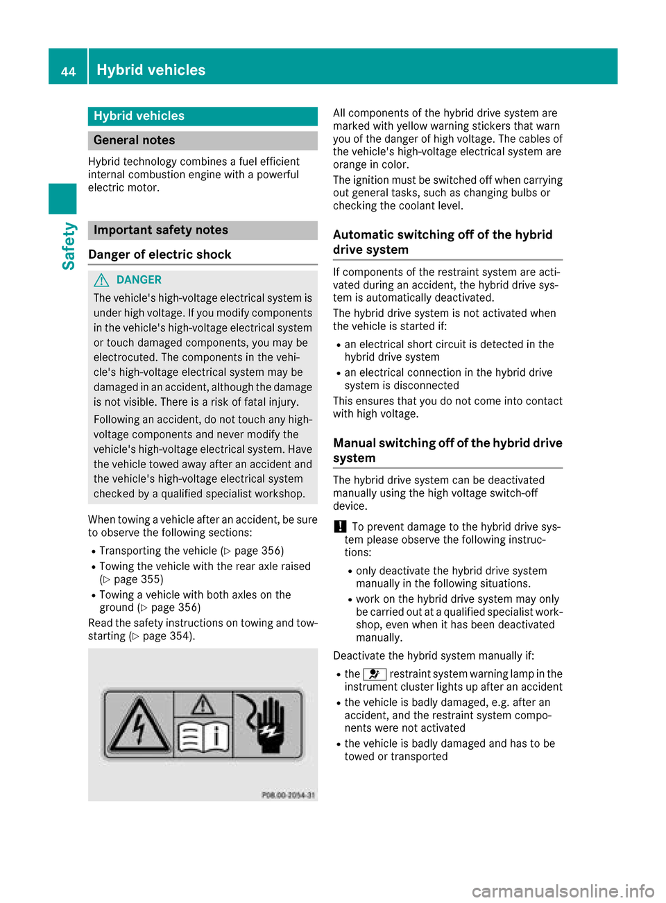
All components of the hybrid drive system are
marked with yellow warning stickers that warn
you of the danger of high voltage. The cables of
the vehicle's high-voltage electrical system are
orange in color.
The ignition must be switched off when carrying
out general tasks, such as changing bulbs or
checking the coolant level.
Automatic switching off of the hybrid
drive system
If components of the restraint system are acti-
vated during an accident, the hybrid drive sys-
tem is automatically deactivated.
The hybrid drive system is not activated when
the vehicle is started if:
Ran electrical short circuit is detected in the
hybrid drive system
Ran electrical connection in the hybrid drive
system is disconnected
This ensures that you do not come into contact
with high voltage.
Manual switching off of the hybrid drive
system
The hybrid drive system can be deactivated
manually using the high voltage switch-off
device.
!To prevent damage to the hybrid drive sys-
tem please observe the following instruc-
tions:
Ronly deactivate the hybrid drive system
manually in the following situations.
Rwork on the hybrid drive system may only
be carried out at a qualified specialist work-
shop, even when it has been deactivated
manually.
Deactivate the hybrid system manually if:
Rthe 6 restraint system warning lamp in the
instrument cluster lights up after an accident
Rthe vehicle is badly damaged, e.g. after an
accident, and the restraint system compo-
nents were not activated
Rthe vehicle is badly damaged and has to be
towed or transported
44Hybrid vehicles
Safety
Page 65 of 398
Installing a child restraint system:
XMake sure you observe the child restraint
system manufacturer's installation instruc-
tions.
XPull the seat belt smoothly from the belt out-
let.
XEngage seat belt tongue in belt buckle.
Activating the special seat belt retractor:
XPull the seat belt out fully and let the inertia
reel retract it again.
While the seat belt is retracting, you should
hear a ratcheting sound. The special seat belt
retractor is enabled.
XPush the child restraint system down so that
the seat belt is tight and does not loosen.
Removing the child restraint system and deac-
tivating the special seat belt retractor:
XMake sure you observe the child restraint
system manufacturer's installation instruc-
tions.
XPress the release button of the seat belt
buckle and guide the seat belt tongue back
towards the belt sash guide.
The special seat belt retractor is deactivated.
Child restraint system
The use of seat belts and child restraint systems
is required by law in:
Rall 50 states
Rthe U.S. territories
Rthe District of Columbia
Rall Canadian provinces
You can obtain further information about the
correct child restraint system from any author-
ized Mercedes-Benz Center.
GWARNING
If the child restraint system is installed incor-
rectly on a suitable seat, it cannot protect as
intended. The child cannot then be restrained
in the event of an accident, heavy braking or
sudden changes of direction. There is an
increased risk of injury, possibly even fatal.
Make sure that you observe the child restraint
system manufacturer's installation instruc-
tions and the notes on use. Please ensure,
that the base of the child restraint system is
always resting completely on the seat cush-
ion. Never place objects, e.g. cushions, under or behind the child restraint system. Only use
child restraint systems with the original cover
designed for them. Only replace damaged
covers with genuine covers.
GWARNING
If the child restraint system is installed incor-
rectly or is not secured, it can come loose in
the event of an accident, heavy braking or a
sudden change in direction. The child
restraint system could be thrown about, strik-
ing vehicle occupants. There is an increased
risk of injury, possibly even fatal.
Always install child restraint systems prop-
erly, even if they are not being used. Make
sure that you observe the child restraint sys-
tem manufacturer's installation instructions.
You will find further information on stowing
objects, luggage or loads under "Loading guide-
lines" (
Ypage 308).
GWARNING
Child restraint systems or their securing sys-
tems which have been damaged or subjected
to a load in an accident can no longer protect
as intended. The child cannot then be
restrained in the event of an accident, heavy
braking or sudden changes of direction. There is an increased risk of injury, possibly even
fatal.
Replace child restraint systems which have
been damaged or subjected to a load in an
accident as soon as possible. Have the secur-
ing systems on the child restraint system
checked at a qualified specialist workshop,
before you install a child restraint system
again.
The securing systems of child restraint systems
are:
Rthe seat belt system
Rthe LATCH-type (ISOFIX) securing rings
Rthe Top Tether anchorages
If it is absolutely necessary to carry a child on
the front-passenger seat, be sure to observe the
Children in the vehicle63
Safety
Z
Page 75 of 398
GWARNING
Adaptive Brake Assist does not react:
Rto people or animals
Rto oncoming vehicles
Rto crossing traffic
Rwhen cornering
As a result, the Adaptive Brake Assist may not
intervene in all critical conditions. There is a
risk of an accident.
Always pay careful attention to the traffic sit- uation and be ready to brake.
Due to the nature of the system, particularly
complicated but non-critical driving conditions
may also cause Brake Assist to intervene.
If adaptive Brake Assist is not available due to a
malfunction in the radar sensor system, the
brake system remains available with full brake
boosting effect and BAS.
ESP®(Electronic Stability Program)
General notes
iObserve the "Important safety notes" sec-
tion (Ypage 68).
ESP
®monitors driving stability and traction, i.e.
power transmission between the tires and the
road surface.
If ESP
®detects that the vehicle is deviating from
the direction desired by the driver, one or more
wheels are braked to stabilize the vehicle. The
engine output is also modified to keep the vehi-
cle on the desired course within physical limits.
ESP
®assists the driver when pulling away on
wet or slippery roads. ESP®can also stabilize
the vehicle during braking.
ETS/4ETS (Electronic Traction System)
iObserve the "Important safety notes" sec-
tion (Ypage 68).
ETS traction control is part of ESP
®. On vehicles
with 4MATIC, 4ETS is part of ESP®.
Traction control brakes the drive wheels indi-
vidually if they spin. This enables you to pull
away and accelerate on slippery surfaces, for
example if the road surface is slippery on one side. In addition, more drive torque is transfer-
red to the wheel or wheels with traction.
Traction control remains active, even if you
deactivate ESP
®.
Important safety notes
iObserve the "Important safety notes" sec-
tion (Ypage 68).
GWARNING
If ESP
®is malfunctioning, ESP®is unable to
stabilize the vehicle. Additionally, further driv-
ing safety systems are deactivated. This
increases the risk of skidding and an accident.
Drive on carefully. Have ESP
®checked at a
qualified specialist workshop.
When towing the vehicle with the rear axle
raised, observe the notes on ESP
®
(Ypage 355).
If the å ESP®OFF warning lamp lights up
continuously, ESP®is deactivated.
If the ÷ ESP®warning lamp lights up contin-
uously, ESP®is not available due to a malfunc-
tion.
Observe the information on warning lamps
(
Ypage 290) and display messages which may
be shown in the instrument cluster
(
Ypage 256).
Only use wheels with the recommended tire
sizes. Only then will ESP
®function properly.
Characteristics of ESP®
General information
If the ÷ ESP warning lamp goes out before
beginning the journey, ESP®is automatically
active.
If ESP
®intervenes, the ÷ESP®warning lamp
flashes in the instrument cluster.
If ESP
®intervenes:
XDo not deactivate ESP®under any circum-
stances.
XOnly depress the accelerator pedal as far as
necessary when pulling away.
XAdapt your driving style to suit the prevailing
road and weather conditions.
Driving safety systems73
Safety
Z
Page 159 of 398
There is a risk of an accident and injury.
When leaving the vehicle, always take the
SmartKey with you and lock the vehicle. Never
leave children or animals unattended in the
vehicle. Always keep the SmartKey out of
reach of children.
XIf the transmission is in positionDor R: push
the DIRECT SELECT lever up or down to the
first point of resistance.
XIf the transmission is in position P: depress
the brake pedal and push the DIRECT SELECT
lever up or down to the first point of resist-
ance.
If you switch the engine off with the transmis-
sion in position Ror D, the automatic transmis-
sion shifts to Nautomatically.
With the SmartKey: if you then open the driv-
er's door or the front-passenger door or remove
the SmartKey from the ignition, the automatic
transmission shifts to Pautomatically.
With the Start/Stop button: if you then open
the driver's door or the front-passenger door,
the automatic transmission shifts to Pautomat-
ically.
If you want the automatic transmission to
remain in neutral N, e.g. when having the vehicle
cleaned in an automatic car wash with a towing
system:
XVehicles with the Start-Stop button:
remove the Start-Stop button from the igni-
tion lock.
XInsert the SmartKey into the ignition lock.
XAll vehicles: switch the ignition on.
XDepress the brake pedal and keep it
depressed.
XShift to neutral N.
XRelease the brake pedal.
XRelease the electric parking brake.
XSwitch off the ignition and leave the SmartKey
in the ignition lock.
Engaging drive position D
XIf the transmission is in position Ror N: push
the DIRECT SELECT lever down past the first
point of resistance.
XIf the transmission is in position P: depress
the brake pedal and push the DIRECT SELECT lever down past the first point of resistance.
Transmission position and drive pro-
gram display
The current transmission position and drive pro-
gram appear in the multifunction display.
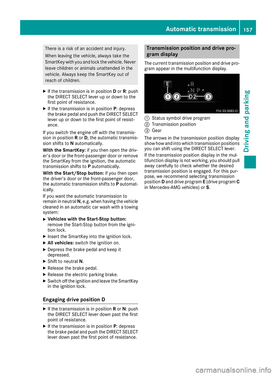
:Status symbol drive program
;Transmission position
=Gear
The arrows in the transmission position display
show how and into which transmission positions
you can shift using the DIRECT SELECT lever.
If the transmission position display in the mul-
tifunction display is not working, you should pull
away carefully to check whether the desired
transmission position is engaged. For this pur-
pose, we recommend selecting transmission
position Dand drive program E(drive program C
in Mercedes-AMG vehicles) or S.
Automatic transmission157
Driving and parking
Z
Page 173 of 398
on again, the charging process resumes auto-
matically. Following an interruption in the
power supply or tripping of the building's fuse,
it may take up to 10 minutes for charging to
resume automatically.
Switch on the building protection system again
after it has been triggered. Otherwise, the
charging process cannot be continued.
General information about the charging
procedure
Pay attention to the "Important safety notes"
(Ypage 168).
The vehicle socket is located in the rear bumper
on the right below the tail lamp.
The charge socket flap and the vehicle are cen-
trally locked or unlocked simultaneously.
Charging the high-voltage battery via
the electrical outlet
Charging cable for electrical outlets
Important safety notes
!Only use the charging cable to charge the
high-voltage battery. Do not use the charging
cable for other purposes. It may otherwise be
damaged.
A charging cable for connection to the electrical outlet is included with the vehicle. Only use the
charging cable included with the vehicle or
charging cables that have been approved for the
vehicle.
iIf you use the supplied 12 A charging cable
to charge a high-voltage battery:
Rthe charge time increases considerably
Relectrical consumption increases consider-
ably
Where possible, charge the high-voltage bat-
tery at a charging station (
Ypage 174). Only
then can certified electrical energy consump-
tion levels be reached.
iThe charging process can vary depending on
the power supply. Therefore, always observe
the local information.
Information about charging from a wallbox
(
Ypage 173). Information on charging at a charging station
(
Ypage 174).
Stowing the charging cable
The charging cable can be stowed in the bag
supplied in the trunk/cargo compartment of the
vehicle and held in place with the Velcro fas-
tener.
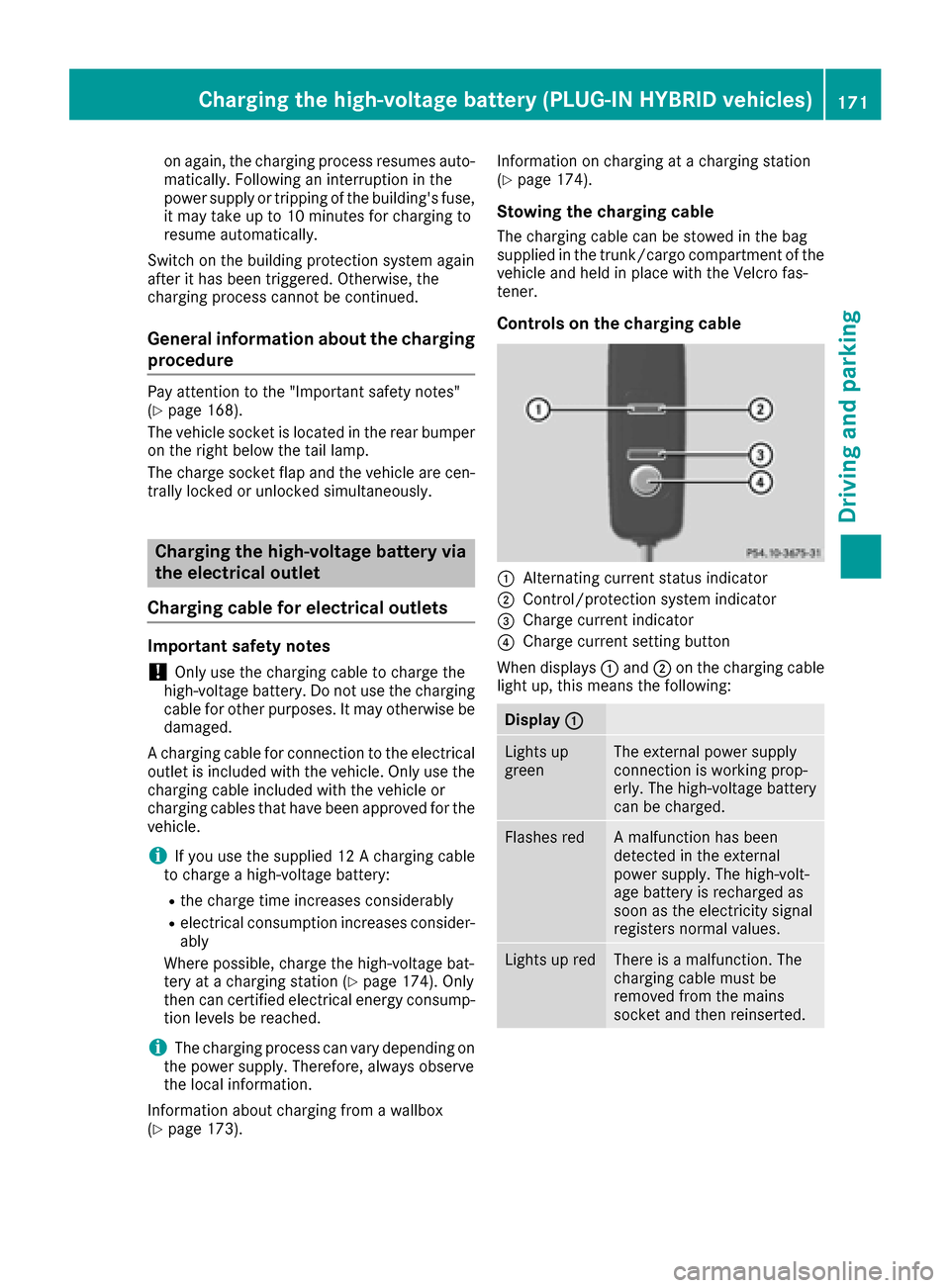
Controls on the charging cable
:Alternating current status indicator
;Control/protection system indicator
=Charge current indicator
?Charge current setting button
When displays :and ;on the charging cable
light up, this means the following:
Display :
Lights up
greenThe external power supply
connection is working prop-
erly. The high-voltage battery
can be charged.
Flashes redA malfunction has been
detected in the external
power supply. The high-volt-
age battery is recharged as
soon as the electricity signal
registers normal values.
Lights up redThere is a malfunction. The
charging cable must be
removed from the mains
socket and then reinserted.
Charging the high-voltage battery (PLUG-IN HYBRID vehicles)171
Driving and parking
Z
Page 179 of 398
Parking
Important safety notes
GWARNING
Flammable material such as leaves, grass or
twigs may ignite if they come into contact with
hot parts of the exhaust system or exhaust
gas flow. There is a risk of fire.
Park the vehicle so that no flammable mate-
rials come into contact with parts of the vehi-
cle which are hot. Take particular care not to
park on dry grassland or harvested grain
fields.
GWARNING
If you leave children unsupervised in the vehi-
cle, they could set it in motion by, for example:
Rrelease the parking brake.
Rshift the automatic transmission out of the
parking position P.
Rstart the engine.
In addition, they may operate vehicle equip-
ment and become trapped. There is a risk of
an accident and injury.
When leaving the vehicle, always take the
SmartKey with you and lock the vehicle. Never
leave children unsupervised in the vehicle.
!Always secure the vehicle correctly against
rolling away. Otherwise, the vehicle or its driv-
etrain could be damaged.
To ensure that the vehicle is secured against
rolling away unintentionally:
Rthe electric parking brake must be applied.
Rthe transmission must be in position Pand the
SmartKey must be removed from the ignition
lock.
Rthe front wheels must be turned towards the
curb on steep uphill or downhill gradients.
Rthe empty vehicle must be secured at the
front axle with a wheel chock or similar, for
example, on uphill or downhill gradients.
Ra laden vehicle must also be secured at the
rear axle with a wheel chock or similar, for
example, on uphill or downhill gradients.
Switching off the engine
Important safety notes
GWARNING
The automatic transmission switches to neu-
tral position Nwhen you switch off the engine.
The vehicle may roll away. There is a risk of an
accident.
After switching off the engine, always switch
to parking position P. Prevent the parked vehi-
cle from rolling away by applying the parking
brake.
Vehicles with automatic transmission
XApply the electric parking brake.
XShift the transmission to position P.
XWith the SmartKey:turn the SmartKey to
position 0in the ignition lock and remove it.
The immobilizer is activated.
XWith the Start/Stop button: press the
Start/Stop button (Ypage 146).
The engine stops and all the indicator lamps in
the instrument cluster go out.
When the driver's door is closed, this corre-
sponds to SmartKey position 1. When the
driver's door is open, this corresponds to
SmartKey position 0: "SmartKey removed".
If you switch the engine off with the transmis-
sion in position Ror D, the automatic transmis-
sion shifts to Nautomatically.
With the SmartKey: if you then open the driv-
er's door or the front-passenger door or remove the SmartKey from the ignition, the automatic
transmission shifts to Pautomatically.
With the Start/Stop button: if you then open
the driver's door or the front-passenger door,
the automatic transmission shifts to Pautomat-
ically.
If you want the automatic transmission to
remain in neutral N, e.g. when having the vehicle
cleaned in an automatic car wash with a towing system:
XVehicles with the Start-Stop button:
remove the Start-Stop button from the igni-
tion lock.
XInsert the SmartKey into the ignition lock.
XAll vehicles: switch the ignition on.
Parking177
Driving and parking
Z
Page 189 of 398
Change into a lower gearingood time on long
and steep downhillgradients. This isespecially
impo rtant ifthe veh icle isladen. By doing so, you
will make use of the braking effect of the engine.
This relieves the load on the brake system and
prevents the brakes from overheating and wear-
ing too quickly.
If DI ST RONIC PLUS detects that there isa risk of
a co llisio n, you will be warned visually and
acoustically. DI STRONIC PLUS cannot prevent a
co llisio nwit hout your intervention. An intermit-
tent warning tone willthen sound and the dis-
tance warning lamp willlight up inthe instru-
ment cluster. Brake immediately inorder to
increase the distance to the veh icle infront or
take evasive action pro videdit is safe to doso.
DI ST RONIC PLUS operates inrange between
0 mph (0 km/h) and 120 mph (200 km/h).
Do not use DI STRONIC PLUS while driving on
roads with steep gradients.
As DI STRONIC PLUS transmits radar waves, it
can resemble the radar detectors of the respon-
sible authorities. You can refer to the relevant
chapter inthe Operator's Manual ifquestions
are asked about this.
iUSA only: This device has been approved by
the FCC as a "Vehicular Radar System". The
radar sensor isintended for use inan auto-
motive radar system only. Removal, tamper-
in
g, or altering of the device willvoid any war-
ranties, and isnot permitted bythe FCC. Do
not tamper with, alter, or use inany non-
approved way.
Any unauthorized mod ification to th isdevice
could void the user's authority to operate the
equipm ent.
iCanada only: This device co mplieswit h
RSS -210 of Industry Canada. Operation is
subject to the foll owing two conditions:
1. This device may not cause harmful inter-
ference, and
2. This device must accept any interference
receive d,inc ludin g interference that may
cause undesired operation of the device.
Removal, tampering, or altering of the device
will void any warranties, and isnot permitte d.
Do not tamper with, alter, or use inany non-
approved way.
Any unauthorized mod ification to th isdevice
could void the user's authority to operate the
equipm ent.
Important safety notes
GWARNING
DISTRONIC PLUS does not react to:
Rpeople or animals
Rstationary obstacles on the road, e.g. stop- ped or parked vehicles
Roncoming and crossing traffic
As a result, DI STRONIC PLUS may neither give
warnings nor intervene insuch situations.
There is a risk of an accident.
Alwa ys pay careful attention to the traff icsit-
uation and be ready to brake.
GWARNING
DISTRONIC PLUS cannot always clearly iden-
tify other road users and co mplex traffic sit-
uations.
In such cases, DI STRONIC PLUS may:
Rgive an unnecessary warning and then
brake the vehicle
Rneither givea warning nor intervene
Raccelerate or brake unexpect edly
There isa risk of an accident.
Continue to drive carefully and be ready to
brake, in particular when warned to do so by
DISTRONIC PLU S.
GWARNING
DISTRONIC PLUS brakes your vehicle with up to 50 %of the maximum possible deceleration.
If this braking force is insufficient, DISTRONIC
PLUS warns you visually and audibly. There is a risk of an accident.
In such cases, apply the brakes yourself and
try to take evasive action.
!If DISTRONIC PLUS or the HOLD function is
activated, the vehicle brakes automatically in
certain situations.
To prevent damage to the vehicle, deactivate
DISTRONIC PLUS and the HOLD function in
the following or other similar situations:
Rwhen towing the vehicle
Rin the car wash
Driving systems187
Driving and parking
Z