rear view mirror MERCEDES-BENZ C-CLASS SEDAN 2018 User Guide
[x] Cancel search | Manufacturer: MERCEDES-BENZ, Model Year: 2018, Model line: C-CLASS SEDAN, Model: MERCEDES-BENZ C-CLASS SEDAN 2018Pages: 370, PDF Size: 6.25 MB
Page 112 of 370
If you come into contact with the electrolyte,
observe the following:
RRinse off the electrolyte from your skin
immediately with water.
RImmediately rinse the electrolyte out of
your eyes thoroughly with clean water.
RIf the electrolyte is swallowed, immediately
rinse your mouth out thoroughly. Do not
induce vomiting.
RIf electrolyte comes into contact with your
skin or hair or is swallowed, seek medical
attention immediately.
RImmediately change out of clothing which
has come into contact with electrolyte.
RIf an allergic reaction occurs, seek medical
attention immediately.
The exterior mirror on the driver's side and the
rear-view mirror automatically go into anti-glare
mode if:
Rthe ignition is switched on
Rincident light from headlamps strikes the sen-
sor in the rear-view mirror
The mirrors do not go into anti-glare mode if
reverse gear is engaged or if the interior lighting
is switched on.
Parking position for the exterior mir-
ror on the front-passenger side
Storing the parking position
You can set the front-passenger side exterior
mirror such that you can see the rear wheel on
that side as soon as you engage reverse gear.
You can store this position.
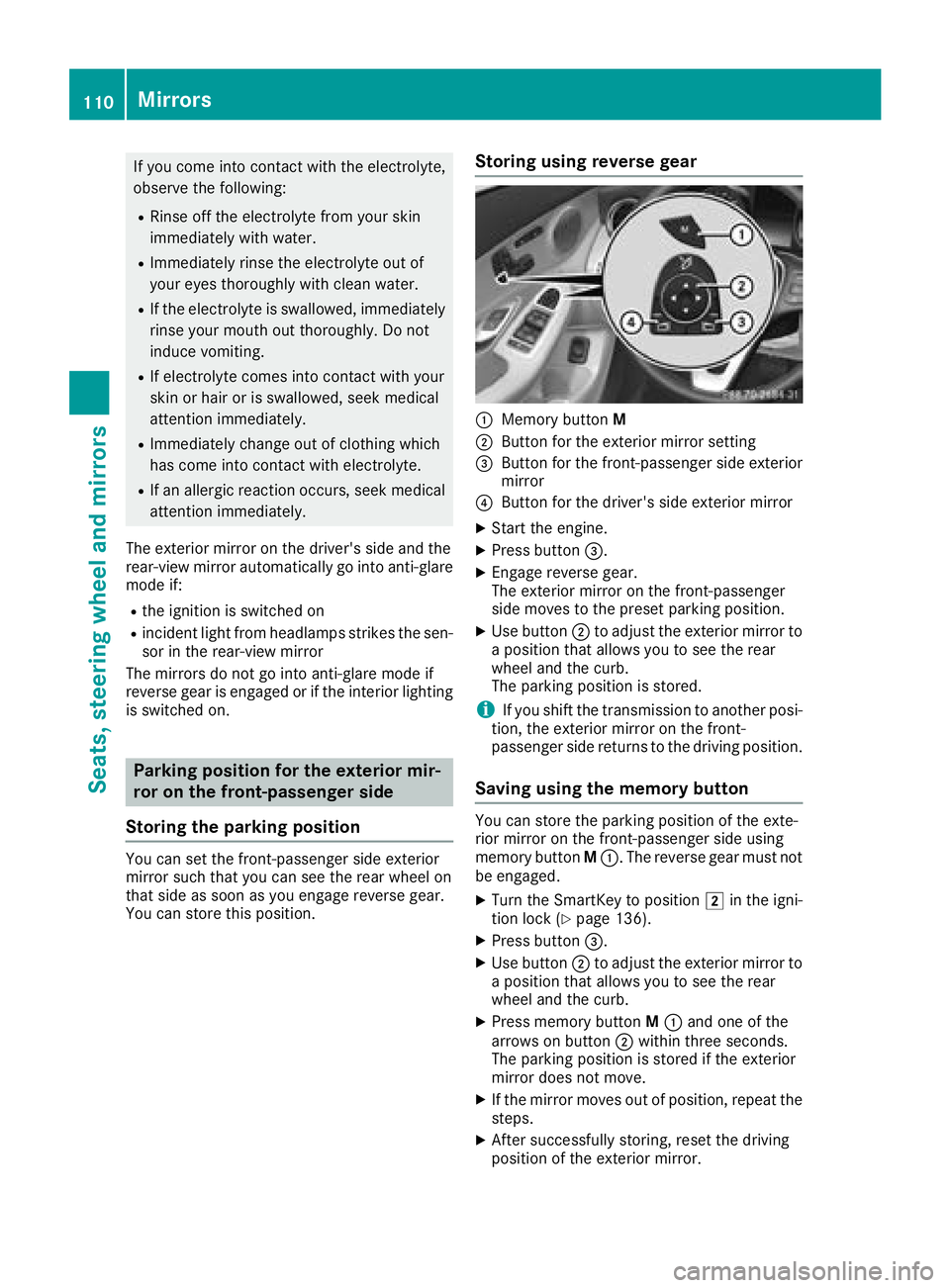
Storing using reverse gear
:Memory button M
;Button for the exterior mirror setting
=Button for the front-passenger side exterior
mirror
?Button for the driver's side exterior mirror
XStart the engine.
XPress button=.
XEngage reverse gear.
The exterior mirror on the front-passenger
side moves to the preset parking position.
XUse button;to adjust the exterior mirror to
a position that allows you to see the rear
wheel and the curb.
The parking position is stored.
iIf you shift the transmission to another posi-
tion, the exterior mirror on the front-
passenger side returns to the driving position.
Saving using the memory button
You can store the parking position of the exte-
rior mirror on the front-passenger side using
memory button M:. The reverse gear must not
be engaged.
XTurn the SmartKey to position 2in the igni-
tion lock (Ypage 136).
XPress button =.
XUse button;to adjust the exterior mirror to
a position that allows you to see the rear
wheel and the curb.
XPress memory button M: and one of the
arrows on button ;within three seconds.
The parking position is stored if the exterior
mirror does not move.
XIf the mirror moves out of position, repeat the
steps.
XAfter successfully storing, reset the driving
position of the exterior mirror.
110Mirrors
Seats, steering wheel and mirrors
Page 193 of 370
Rear view camera
General notes
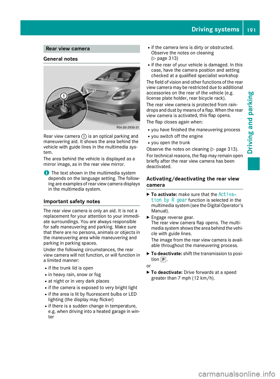
Rear view camera :is an optical parking and
maneuvering aid. It shows the area behind the
vehicle with guide lines in the multimedia sys-
tem.
The area behind the vehicle is displayed as a
mirror image, as in the rear view mirror.
iThe text shown in the multimedia system
depends on the language setting. The follow-
ing are examples of rear view camera displays
in the multimedia system.
Important safety notes
The rear view camera is only an aid. It is not a
replacement for your attention to your immedi-
ate surroundings. You are always responsible
for safe maneuvering and parking. Make sure
that there are no persons, animals or objects in
the maneuvering area while maneuvering and
parking in parking spaces.
Under the following circumstances, the rear
view camera will not function, or will function in
a limited manner:
Rif the trunk lid is open
Rin heavy rain, snow or fog
Rat night or in very dark places
Rif the camera is exposed to very bright light
Rif the area is lit by fluorescent bulbs or LED
lighting (the display may flicker)
Rif there is a sudden change in temperature,
e.g. when driving into a heated garage in win- ter
Rif the camera lens is dirty or obstructed.
Observe the notes on cleaning
(
Ypage 313)
Rif the rear of your vehicle is damaged. In this
case, have the camera position and setting
checked at a qualified specialist workshop
The field of vision and other functions of the rear
view camera may be restricted due to additional
accessories on the rear of the vehicle (e.g.
license plate holder, rear bicycle rack).
The rear view camera is protected from rain-
drops and dust by means of a flap. When the rear view camera is acti vated
, this flap opens.
The flap closes again when:
Ryou have finished the maneuvering process
Ryou switch off the engine
Ryou open the trunk
Observe the notes on cleaning (
Ypage 313).
For technical reasons, the flap may remain open
briefly after the rear view camera has been
deactivated.
Activating/deactivating the rear view
camera
XTo activate: make sure that the Activa‐
tion by R gearfunction is selected in the
multimedia system (see the Digital Operator's
Manual).
XEngage reverse gear.
The rear view camera flap opens. The multi-
media system shows the area behind the vehi-
cle with guide lines.
The image from the rear view camera is avail- able throughout the maneuvering process.
XTo deactivate: shift the transmission to posi-
tion j.
or
XTo deactivate: Drive forwards at a speed
greater than 7 mph (12 km/h).
Driving systems191
Driving and parking
Z
Page 194 of 370
Multimedia display
The rear view camera may show a distorted view
of obstacles, show them incorrectly or not at all.
The rear view camera does not show objects in
the following positions:
Rvery close to the rear bumper
Runder the rear bumper
Rin close range above the handle on the trunk
lid
!Objects not at ground level may appear to
be further away than they actually are, e.g.:
Rthe bumper of a parked vehicle
Rthe drawbar of a trailer
Rthe ball coupling of a trailer tow hitch
Rthe rear section of an HGV
Ra slanted post
Use the guidelines only for orientation.
Approach objects no further than the bottom-
most guideline.
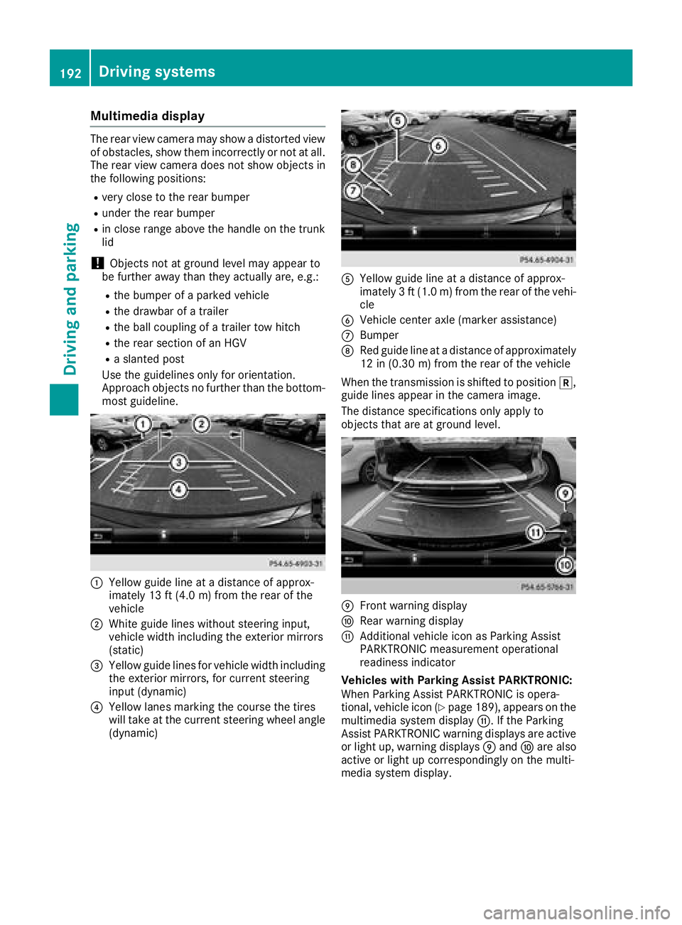
:Yellow guide line at a distance of approx-
imately 13 ft (4.0 m) from the rear of the
vehicle
;White guide lines without steering input,
vehicle width including the exterior mirrors
(static)
=Yellow guide lines for vehicle width including
the exterior mirrors, for current steering
input (dynamic)
?Yellow lanes marking the course the tires
will take at the current steering wheel angle
(dynamic)
AYellow guide line at a distance of approx-
imately 3 ft (1.0 m) from the rear of the vehi-
cle
BVehicle center axle (marker assistance)
CBumper
DRed guide line at a distance of approximately
12 in (0.30 m) from the rear of the vehicle
When the transmission is shifted to position k,
guide lines appear in the camera image.
The distance specifications only apply to
objects that are at ground level.
EFront warning display
FRear warning display
GAdditional vehicle icon as Parking Assist
PARKTRONIC measurement operational
readiness indicator
Vehicles with Parking Assist PARKTRONIC:
When Parking Assist PARKTRONIC is opera-
tional, vehicle icon (
Ypage 189), appears on the
multimedia system display G. If the Parking
Assist PARKTRONIC warning displays are active
or light up, warning displays Eand Fare also
active or light up correspondingly on the multi-
media system display.
192Driving systems
Driving and parking
Page 195 of 370
"Reverse parking" function
Backing up straight into a parking space
without steering input
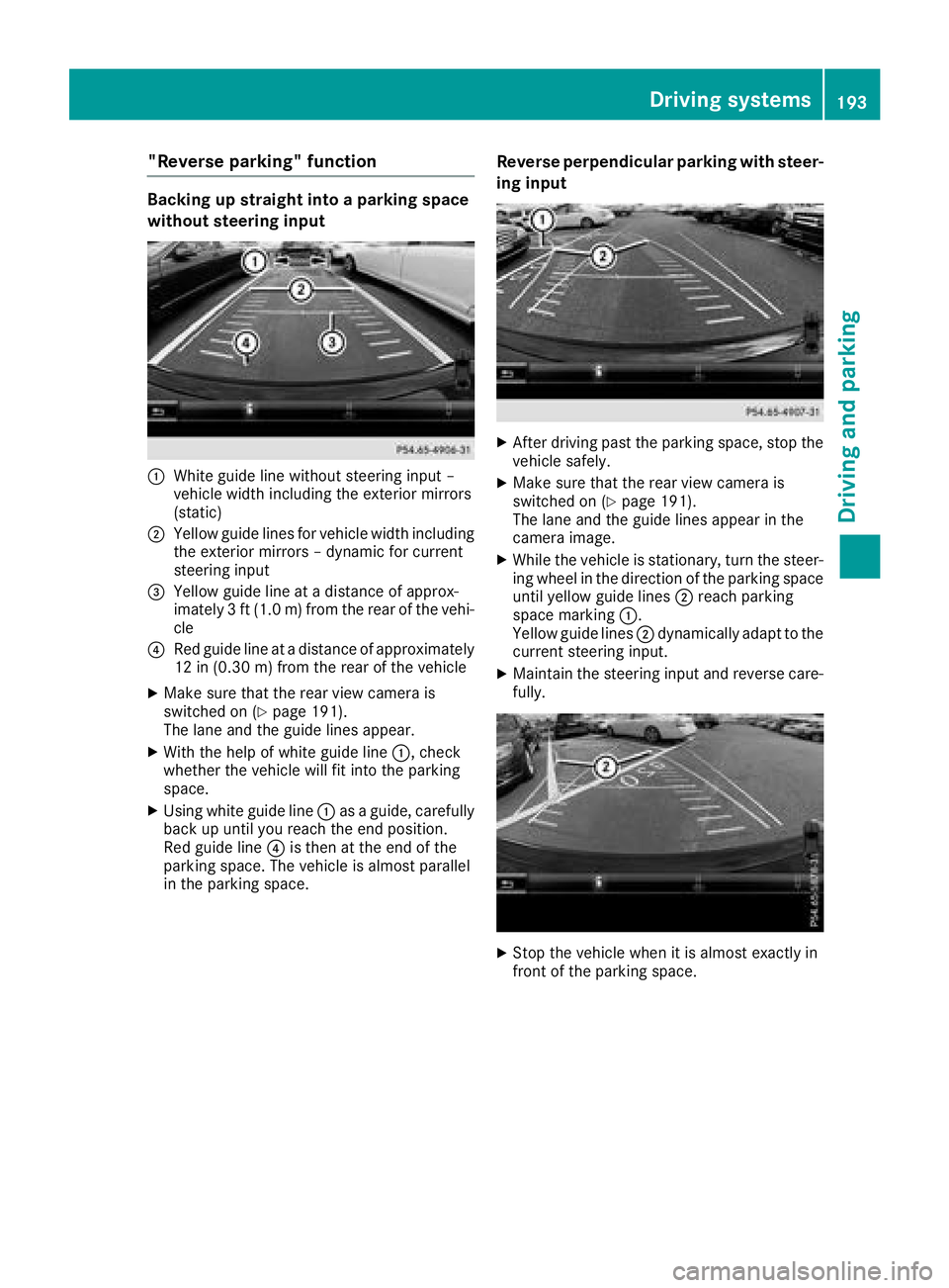
:White guide line without steering input –
vehicle width including the exterior mirrors
(static)
;Yellow guide lines for vehicle width including
the exterior mirrors – dynamic for current
steering input
=Yellow guide line at a distance of approx-
imately 3 ft (1.0 m) from the rear of the vehi-
cle
?Red guide line at a distance of approximately
12 in (0.30m)from the rear of the vehicle
XMake sure that the rear view camera is
switched on (Ypage 191).
The lane and the guide lines appear.
XWith the help of white guide line :, check
whether the vehicle will fit into the parking
space.
XUsing white guide line :as a guide, carefully
back up until you reach the end position.
Red guide line ?is then at the end of the
parking space. The vehicle is almost parallel
in the parking space.
Reverse perpendicular parking with steer-
ing input
XAfter driving past the parking space, stop the
vehicle safely.
XMake sure that the rear view camera is
switched on (Ypage 191).
The lane and the guide lines appear in the
camera image.
XWhile the vehicle is stationary, turn the steer-
ing wheel in the direction of the parking space
until yellow guide lines ;reach parking
space marking :.
Yellow guide lines ;dynamically adapt to the
current steering input.
XMaintain the steering input and reverse care-
fully.
XStop the vehicle when it is almost exactly in
front of the parking space.
Driving systems193
Driving and parking
Z
Page 197 of 370
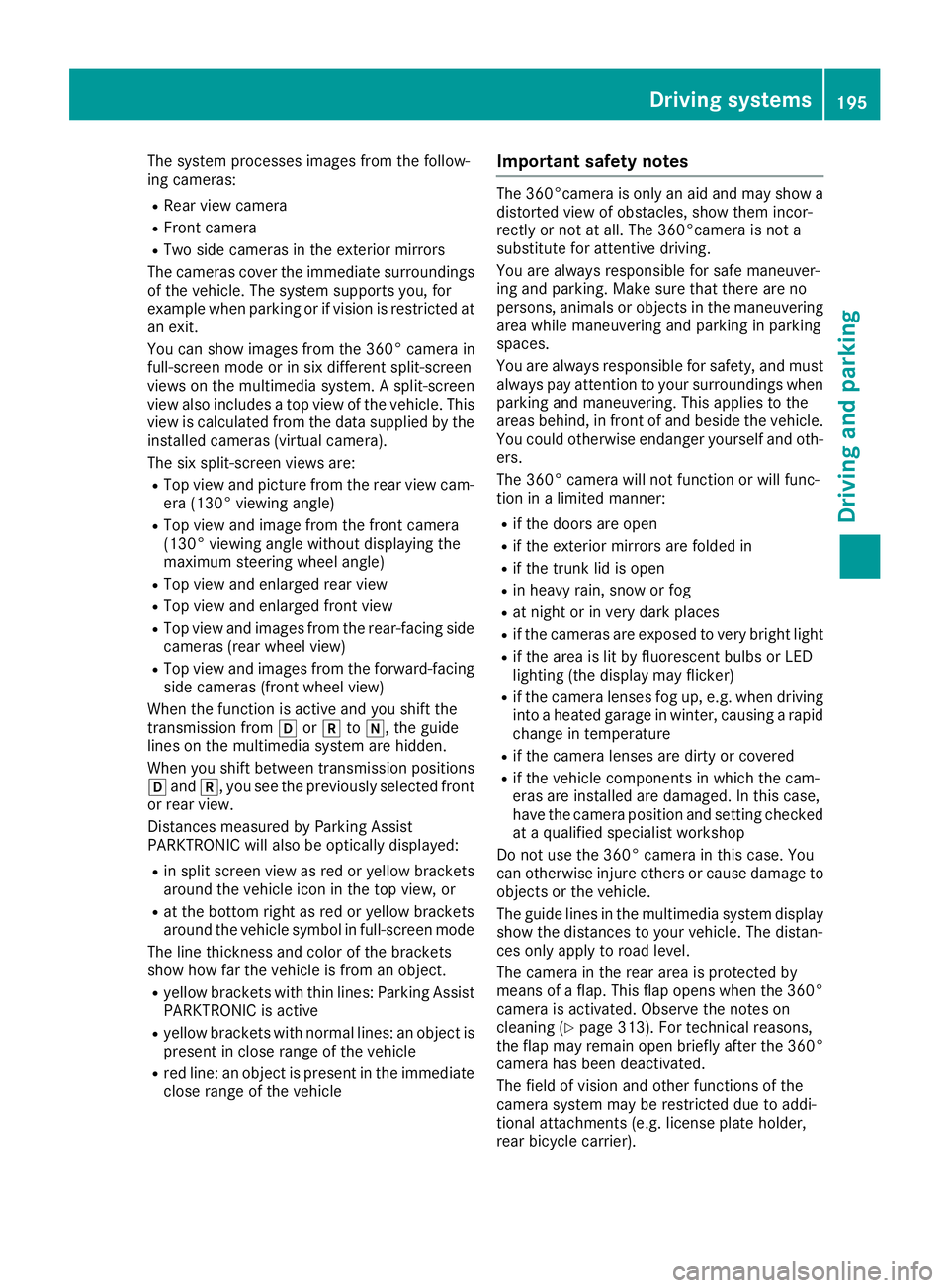
The system processes images from the follow-
ing cameras:
RRear view camera
RFront camera
RTwo side cameras in the exterior mirrors
The cameras cover the immediate surroundings
of the vehicle. The system supports you, for
example when parking or if vision is restricted at
an exit.
You can show images from the 360° camera in
full-screen mode or in six different split-screen
views on the multimedia system. A split-screen
view also includes a top view of the vehicle. This
view is calculated from the data supplied by the installed cameras (virtual camera).
The six split-screen views are:
RTop view and picture from the rear view cam-
era (130° viewing angle)
RTop view and image from the front camera
(130° viewing angle without displaying the
maximum steering wheel angle)
RTop view and enlarged rear view
RTop view and enlarged front view
RTop view and images from the rear-facing side
cameras (rear wheel view)
RTop view and images from the forward-facing
side cameras (front wheel view)
When the function is active and you shift the
transmission from hork toi, the guide
lines on the multimedia system are hidden.
When you shift between transmission positions
h and k, you see the previously selected front
or rear view.
Distances measured by Parking Assist
PARKTRONIC will also be optically displayed:
Rin split screen view as red or yellow brackets
around the vehicle icon in the top view, or
Rat the bottom right as red or yellow brackets
around the vehicle symbol in full-screen mode
The line thickness and color of the brackets
show how far the vehicle is from an object.
Ryellow brackets with thin lines: Parking Assist
PARKTRONIC is active
Ryellow brackets with normal lines: an object is present in close range of the vehicle
Rred line: an object is present in the immediate
close range of the vehicle
Important safety notes
The 360°camera is only an aid and may show a
distorted view of obstacles, show them incor-
rectly or not at all. The 360°camera is not a
substitute for attentive driving.
You are always responsible for safe maneuver-
ing and parking. Make sure that there are no
persons, animals or objects in the maneuvering
area while maneuvering and parking in parking
spaces.
You are always responsible for safety, and must
always pay attention to your surroundings when
parking and maneuvering. This applies to the
areas behind, in front of and beside the vehicle.
You could otherwise endanger yourself and oth-
ers.
The 360° camera will not function or will func-
tion in a limited manner:
Rif the doors are open
Rif the exterior mirrors are folded in
Rif the trunk lid is open
Rin heavy rain, snow or fog
Rat night or in very dark places
Rif the cameras are exposed to very bright light
Rif the area is lit by fluorescent bulbs or LED
lighting (the display may flicker)
Rif the camera lenses fog up, e.g. when driving
into a heated garage in winter, causing a rapid
change in temperature
Rif the camera lenses are dirty or covered
Rif the vehicle components in which the cam-
eras are installed are damaged. In this case,
have the camera position and setting checked
at a qualified specialist workshop
Do not use the 360° camera in this case. You
can otherwise injure others or cause damage to
objects or the vehicle.
The guide lines in the multimedia system display
show the distances to your vehicle. The distan-
ces only apply to road level.
The camera in the rear area is protected by
means of a flap. This flap opens when the 360° camera is activated. Observe the notes on
cleaning (
Ypage 313). For technical reasons,
the flap may remain open briefly after the 360°
camera has been deactivated.
The field of vision and other functions of the
camera system may be restricted due to addi-
tional attachments (e.g. license plate holder,
rear bicycle carrier).
Driving systems195
Driving and parking
Z
Page 198 of 370
On vehicles with height-adjustable chassis,
depending on technical conditions, leaving the
standard height can result in:
Rinaccuracies in the guide lines
Rinaccuracies in the display of generated
images (top view)
Activation conditions
The image from the 360° camera appears if:
Rthe multimedia system is switched on
Rthe360° Camerafunction is switched on
If you are driving faster than at a moderate
speed and you turn on the 360° camera, a warn-
ing message appears.
The warning message disappears if:
Ryou are again driving at a moderate speed The 360° camera is then activated
Rthe message is confirmed with the %but-
ton
Switching the 360° camera on and off
using the button
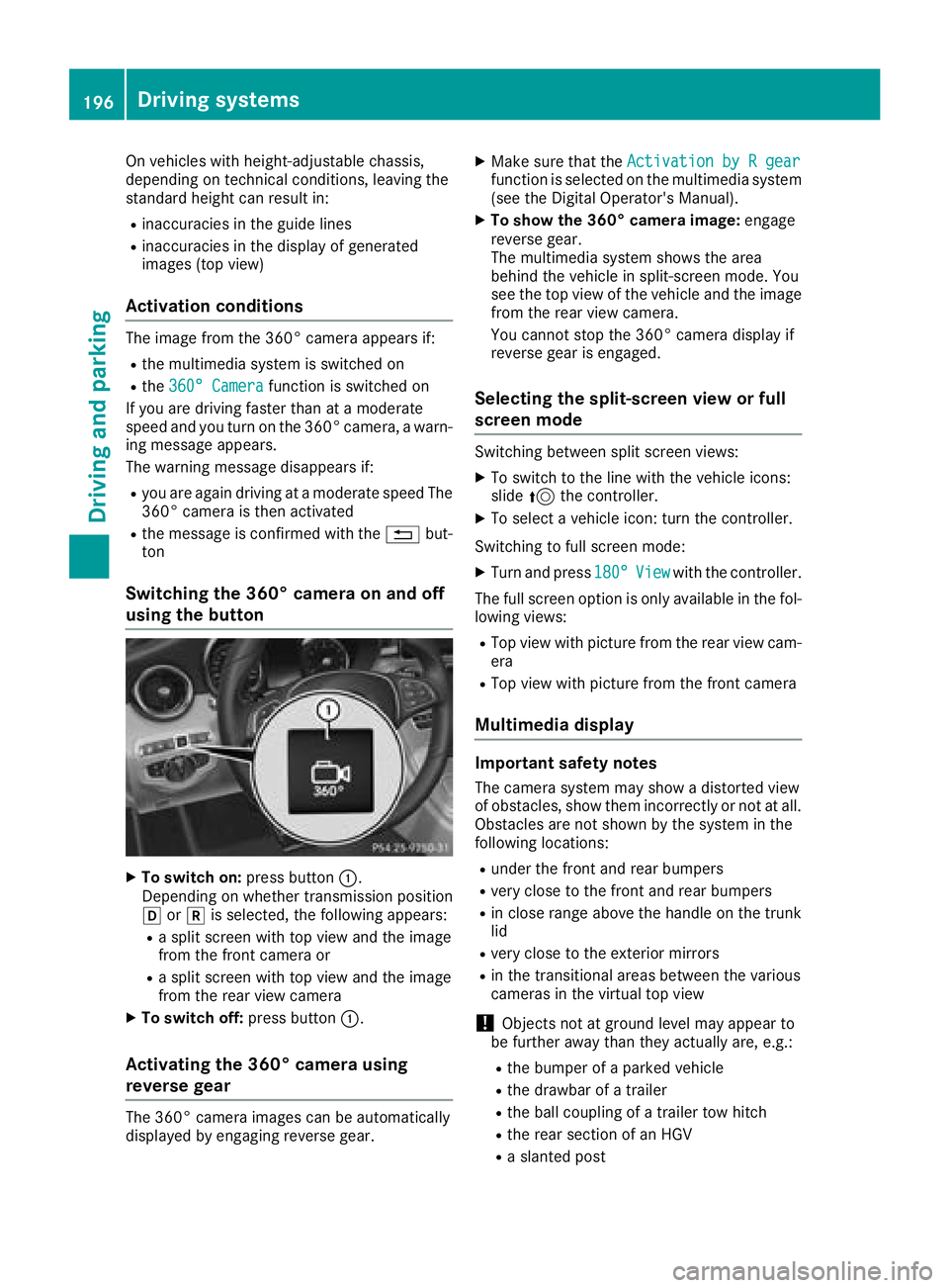
XTo switch on: press button:.
Depending on whether transmission position
h ork is selected, the following appears:
Ra split screen with top view and the image
from the front camera or
Ra split screen with top view and the image
from the rear view camera
XTo switch off: press button:.
Activating the 360° camera using
reverse gear
The 360° camera images can be automatically
displayed by engaging reverse gear.
XMake sure that the Activation by R gearfunction is selected on the multimedia system
(see the Digital Operator's Manual).
XTo show the 360° camera image: engage
reverse gear.
The multimedia system shows the area
behind the vehicle in split-screen mode. You
see the top view of the vehicle and the image
from the rear view camera.
You cannot stop the 360° camera display if
reverse gear is engaged.
Selecting the split-screen view or full
screen mode
Switching between split screen views:
XTo switch to the line with the vehicle icons:
slide 5the controller.
XTo select a vehicle icon: turn the controller.
Switching to full screen mode:
XTurn and press 180°Viewwith the controller.
The full screen option is only available in the fol-
lowing views:
RTop view with picture from the rear view cam-
era
RTop view with picture from the front camera
Multimedia display
Important safety notes
The camera system may show a distorted view
of obstacles, show them incorrectly or not at all.
Obstacles are not shown by the system in the
following locations:
Runder the front and rear bumpers
Rvery close to the front and rear bumpers
Rin close range above the handle on the trunk
lid
Rvery close to the exterior mirrors
Rin the transitional areas between the various
cameras in the virtual top view
!Objects not at ground level may appear to
be further away than they actually are, e.g.:
Rthe bumper of a parked vehicle
Rthe drawbar of a trailer
Rthe ball coupling of a trailer tow hitch
Rthe rear section of an HGV
Ra slanted post
196Driving systems
Driving and parking
Page 199 of 370
Use the guidelines only for orientation.
Approach objects no further than the bottom-
most guideline.
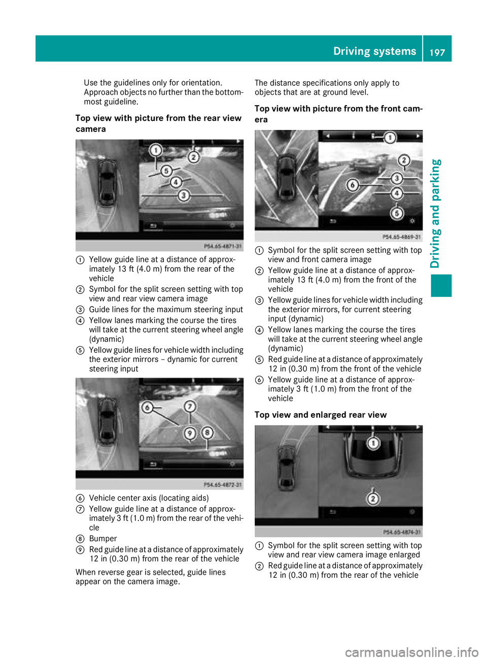
Top view with picture from the rear view
camera
:Yellow guide line at a distance of approx-
imately 13 ft (4.0 m) from the rear of the
vehicle
;Symbol for the split screen setting with top
view and rear view camera image
=Guide lines for the maximum steering input
?Yellow lanes marking the course the tires
will take at the current steering wheel angle
(dynamic)
AYellow guide lines for vehicle width including
the exterior mirrors – dynamic for current
steering input
BVehicle center axis (locating aids)
CYellow guide line at a distance of approx-
imately 3 ft (1.0 m) from the rear of the vehi-
cle
DBumper
ERed guide line at a distance of approximately
12 in (0.30 m) from the rear of the vehicle
When reverse gear is selected, guide lines
appear on the camera image. The distance specifications only apply to
objects that are at ground level.
Top view with picture from the front cam-
era
:Symbol for the split screen setting with top
view and front camera image
;Yellow guide line at a distance of approx-
imately 13 ft (4.0 m) from the front of the
vehicle
=Yellow guide lines for vehicle width including
the exterior mirrors, for current steering
input (dynamic)
?Yellow lanes marking the course the tires
will take at the current steering wheel angle
(dynamic)
ARed guide line at a distance of approximately
12 in (0.30 m) from the front of the vehicle
BYellow guide line at a distance of approx-
imately 3 ft (1.0 m) from the front of the
vehicle
Top view and enlarged rear view
:Symbol for the split screen setting with top
view and rear view camera image enlarged
;Red guide line at a distance of approximately
12 in (0.30
m)from the rear of the vehicle
Driving systems197
Driving and parking
Z
Page 200 of 370
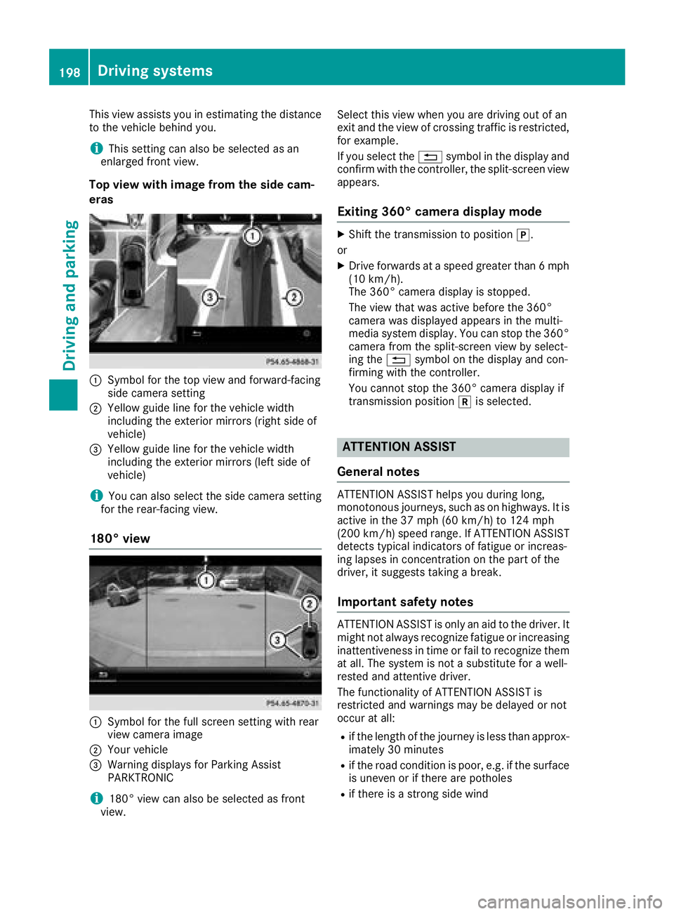
This view assists you in estimating the distance
to the vehicle behind you.
iThis setting can also be selected as an
enlarged front view.
Top view with image from the side cam-
eras
:Symbol for the top view and forward-facing
side camera setting
;Yellow guide line for the vehicle width
including the exterior mirrors (right side of
vehicle)
=Yellow guide line for the vehicle width
including the exterior mirrors (left side of
vehicle)
iYou can also select the side camera setting
for the rear-facing view.
180° view
:Symbol for the full screen setting with rear
view camera image
;Your vehicle
=Warning displays for Parking Assist
PARKTRONIC
i180° view can also be selected as front
view. Select this view when you are driving out of an
exit and the view of crossing traffic is restricted,
for example.
If you select the %symbol in the display and
confirm with the controller, the split-screen view
appears.
Exiting 360° camera display mode
XShift the transmission to position j.
or
XDrive forwards at a speed greater than 6 mph (10 km/h).
The 360° camera display is stopped.
The view that was active before the 360°
camera was displayed appears in the multi-
media system display. You can stop the 360°
camera from the split-screen view by select-
ing the %symbol on the display and con-
firming with the controller.
You cannot stop the 360° camera display if
transmission position kis selected.
ATTENTION ASSIST
General notes
ATTENTION ASSIST helps you during long,
monotonous journeys, such as on highways. It is
active in the 37 mph (60 km/h) to 124 mph
(200 km/h) speed range. If ATTENTION ASSIST
detects typical indicators of fatigue or increas-
ing lapses in concentration on the part of the
driver, it suggests taking a break.
Important safety notes
ATTENTION ASSIST is only an aid to the driver. It
might not always recognize fatigue or increasing inattentiveness in time or fail to recognize them
at all. The system is not a substitute for a well-
rested and attentive driver.
The functionality of ATTENTION ASSIST is
restricted and warnings may be delayed or not
occur at all:
Rif the length of the journey is less than approx-
imately 30 minutes
Rif the road condition is poor, e.g. if the surface
is uneven or if there are potholes
Rif there is a strong side wind
198Driving systems
Driving and parking
Page 292 of 370
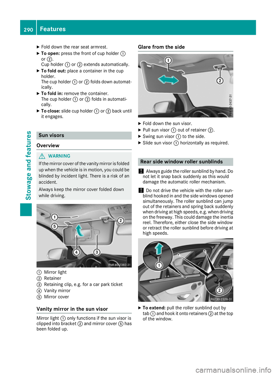
XFold down the rear seat armrest.
XTo open:press the front of cup holder :
or ;.
Cup holder :or; extends automatically.
XTo fold out: place a container in the cup
holder.
The cup holder :or; folds down automat-
ically.
XTo fold in: remove the container.
The cup holder :or; folds in automati-
cally.
XTo close: slide cup holder :or; back until
it engages.
Sun visors
Overview
GWARNING
If the mirror cover of the vanity mirror is folded
up when the vehicle is in motion, you could be
blinded by incident light. There is a risk of an
accident.
Always keep the mirror cover folded down
while driving.
:Mirror light
;Retainer
=Retaining clip, e.g. for a car park ticket
?Vanity mirror
AMirror cover
Vanity mirror in the sun visor
Mirror light :only functions if the sun visor is
clipped into bracket ;and mirror cover Ahas
been folded up.
Glare from the side
XFold down the sun visor.
XPull sun visor :out of retainer ;.
XSwing sun visor :to the side.
XSlide sun visor :horizontally as required.
Rear side window roller sunblinds
!
Always guide the roller sunblind by hand. Do
not let it snap back suddenly as this would
damage the automatic roller mechanism.
!Do not drive the vehicle with the roller sun-
blind hooked in and the side windows opened
simultaneously. The roller sunblind can jump
out of the retainers and spring back suddenly
when driving at high speeds, e.g. when driving
on the freeway. This could damage the inertia
reel. Therefore, either close the side window
or retract the roller sunblind before driving at
high speeds.
XTo extend: pull the roller sunblind out by
tab :and hook it onto retainers ;at the top
of the window.
290Features
Stowage and features
Page 301 of 370
Another function of the Vehicle Health Check is
the transfer of service data to the Customer
Assistance Center. If a service is due, the display
shows a message to this effect together with
information about any special offers at your
workshop.
This information can also be called up under
"Owners Online" at http://www.mbusa.com.
Information on the data stored in the vehicle
(
Ypage 33).
Information on Roadside Assistance
(
Ypage 30).
Downloading routes
Downloading routes allows you to transfer and
save predefined routes in the navigation sys-
tem.
A route can be prepared and sent by either a
customer service representative or under "Own-
ers Online" at http://www.mbusa.com.
Each route can include up to four way points.
Once a route has been received by the naviga-
tion system, you will see the Do
youwanttostart route guidance? DestinationReceived destination has been savedin "Previous destinations".message on
the multimedia system display.
The route is saved.
XTo start route guidance: selectYes.
An overview of the route is shown in the dis-
play.
If you select No
, the saved route can be called
up later in the navigation menu.
XSelect Start.
Route guidance starts.
Downloaded and saved routes can be called up
again.
Speed alert
You can define the upper speed limit, which
must not be exceeded by the vehicle.
If this selected speed is exceeded by the vehicle,
a message will be sent to the Customer Assis-
tance Center. The Customer Assistance Center
then forwards this information to you.
You can select the way in which you receive this
information beforehand. Possible options
include text message, e-mail or an automated
call. The data you receive contains the following
information:
Rthe location where the speed limit was excee-
ded
Rthe time at which the speed limit was excee-
ded
Rthe selected speed limit which was exceeded
Geo fencing
Geo fencing allows you to select areas which the
vehicle should not enter or leave. You will be
informed if the vehicle crosses the boundaries
of the selected areas. You can select the way in
which you receive this information beforehand.
Possible options include text message, e-mail or
an automated call.
The area can be determined as either a circle or
a polygon with a maximum of ten corners. You
can specify up to ten areas simultaneously. Dif-
ferent settings are possible for each area.
These settings can be called up under "Owners
Online" at http://www.mbusa.com.
Alternatively, you can trigger an Info call and
notify the customer service representative that
you wish to activate geo-fencing.
Currently inactive areas can be activated by text
message.
Triggering the vehicle alarm
With this function, you can trigger the vehicle's
panic alarm via text message. An alarm sounds
and the exterior lighting flashes. Depending on
the setting, the panic alarm lasts five or ten sec- onds. Afterwards, the alarm switches off.
Garage door opener
General notes
The HomeLink®garage door opener integrated
in the rear-view mirror allows you to operate up
to three different door and gate systems.
Use the integrated garage door opener only on
garage doors that:
Rhave safety stop and reverse features and
Rmeet current U.S. federal safety standards
Once programed, the integrated garage door
opener in the rear-view mirror will assume the
function of the garage door system's remote
Features299
Stowag ean d features
Z