Trunk light MERCEDES-BENZ C230 KOMPRESSOR COUPE 2002 CL203 Owner's Manual
[x] Cancel search | Manufacturer: MERCEDES-BENZ, Model Year: 2002, Model line: C230 KOMPRESSOR COUPE, Model: MERCEDES-BENZ C230 KOMPRESSOR COUPE 2002 CL203Pages: 399
Page 7 of 399

4 Contents
LIGHTING SYSTEM .................... 300
LIGHT SENSOR........................... 302
DOOR............................................ 302
TRUNK OPEN ............................. 303
HOOD ........................................... 303
TELEPHONE – FUNCTION........ 304
TELE AID ..................................... 304
WASHER FLUID.......................... 305
RESTRAINT SYSTEM ................. 306
KEY ............................................... 306
FUEL RESERVE .......................... 307
UNDERVOLTAGE ........................ 307
STEERING WHEEL ADJUST. ..... 308
Practical hintsFirst aid kit...................................... 310
Stowing things in the vehicle ...... 311
Fuses ................................................ 311
Hood ................................................. 315
Automatic transmission
fluid level ................................... 317
Adding engine oil........................... 318
Coolant level ................................... 319Adding coolant ............................ 319
Windshield and headlamp
washer system .......................... 320
Spare wheel, storage
compartment ............................. 321
Vehicle tools and air pump .......... 322
Vehicle jack .................................... 323
Wheels ............................................ 324
Tire replacement........................ 324
Rotating wheels ......................... 325
Spare wheel .................................... 326
Changing wheels ........................... 327
Inflating the collapsible
spare tire ..................................... 333
Storing spare wheel in
wheel well ................................... 334
Tire inflation pressure ................. 335
Battery............................................. 336
Jump starting.................................. 338
Towing the vehicle ........................ 341
Transmission selector lever,
manually unlocking .................. 344
Exterior lamps ............................... 345
Replacing bulbs ......................... 345Changing batteries in the
electronic main key .................. 351
Synchronizing remote
control .......................................... 353
Emergency engine shut-down ..... 353
Fuel filler flap, manual release ... 354
Replacing wiper blade insert ....... 356
Roof rack ......................................... 357
Vehicle careCleaning and care of
the vehicle.................................. 360
Power washer.............................. 361
Tar stains ..................................... 361
Paintwork, painted body
components ................................. 361
Engine cleaning.......................... 362
Vehicle washing ......................... 362
Ornamental moldings................ 363
Headlamps, taillamps,
turn signal lenses ...................... 363
Window cleaning........................ 363
Wiper blade ................................. 363
Page 34 of 399
31 Central locking system
Te ch n i c a l
data Instruments
and controlsOperationDrivingInstrument
cluster displayPractical hints Car care Index Central locking system
Radio frequency and infrared remote control
The electronic key has an integrated radio frequency
and infrared remote control.
Due to the extended operational range of the remote
control, it could be possible to unintentionally lock or
unlock the vehicle by pressing the transmit button. If
one of the transmit buttons is pressed, the battery check
lamp lights up briefly – indicating that the batteries are
in order. See page 351 for checking batteries.
The vehicle doors, trunk and fuel filler flap can be
centrally locked and unlocked via remote control.
Opening and closing the windows and panorama
sliding/pop-up roof can only be done with the infrared
portion of the remote control. Aim transmitter eye at a
receiver (6 or 7), press and hold transmit button Œ
or ‹, seepage34.
If the electronic key is inserted in starter switch, the
vehicle cannot be locked or unlocked, and the trunk lid
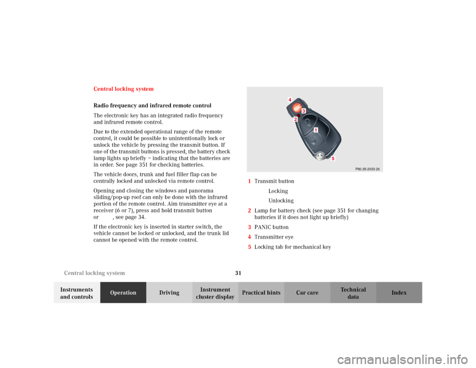
cannot be opened with the remote control.1Transmit button
‹ Locking
ΠUnlocking
2Lamp for battery check (see page 351 for changing
batteries if it does not light up briefly)
3PANIC button
4Transmitter eye
5Locking tab for mechanical key
P80.35-2033-26
2
1
4
3
5
Page 36 of 399
33 Central locking system
Te ch n i c a l
data Instruments
and controlsOperationDrivingInstrument
cluster displayPractical hints Car care Index Locking and unlocking with remote control
Unlocking:
Press transmit button Œ. All turn signal lamps blink
once to indicate that the vehicle is unlocked.
The remote control can be programmed for two kinds of
unlocking modes (see below):
Selective unlocking mode –
Press transmit button Œonce to unlock driver’s door
and fuel filler flap.
Press transmit button Πtwice to unlock all doors,
fuel filler flap, and trunk.
Global unlocking mode –
Press transmit button Œonce to unlock all doors,
fuel filler flap, and trunk.
Notes:
The presently active unlocking mode (selective or
global) can only be determined by unlocking the vehicle
with the remote control (see below for changing mode).If within 40 seconds of unlocking with the remote
control, neither door or trunk is opened, the electronic
key is not inserted in the starter switch, or the central
locking switch is not activated, the vehicle will
automatically lock.
Locking:
Press transmit button ‹ once. All turn signal lamps
blink three times to indicate that the vehicle is locked. If
they do not blink three times, a door or trunk is not
properly closed.
Note:
If the vehicle cannot be locked or unlocked by pressing
the transmit button, then it may be necessary to change
the batteries in the electronic key (if ok, battery check
lamp in electronic key will light briefly when pressing
transmit button) or to synchronize the remote control,
see pages 351 and 353.
Choosing global or selective mode on remote control
Press and hold transmit buttons‹ andŒ
simultaneously for five seconds to reprogram the
remote control. Battery check lamp will blink two times
indicating the completed mode change.
Page 284 of 399
281 Contents - Instrument cluster display
Te ch n i c a l
data Instruments
and controlsOperation DrivingInstrument
cluster displayPractical hints Car care Index
Instrument cluster displayMalfunction and indicator
lamps in the instrument
cluster ......................................... 282
On-board diagnostic system ......... 283
Check engine malfunction
indicator lamp............................. 283
Brake warning lamp .................. 284
Supplemental restraint
system (SRS) indicator lamp .... 285
Fuel reserve warning................. 286
ABS malfunction indicator
lamp.............................................. 287
Electronic stability program
(ESP) — warning lamp ............... 288
Seat belt nonusage warning
lamp ............................................288Malfunction and indicator
lamp in the center console...... 289
AIRBAG OFF indicator lamp .... 289
Malfunction and warning
messages in the
multifunction display .............. 290
DISPLAY DEFECTIVE................ 291
BATTERY / ALTERNATOR ....... 292
ANTILOCK BRAKE SYSTEM .... 293
BRAKE ASSIST........................... 293
BRAKE PAD WEAR.................... 294
BRAKE FLUID ............................ 294
PARKING BRAKE ....................... 295
SEAT BELT SYSTEM .................. 295
ELEC. STABIL. PROG.
(Electronic stability program).. 296
COOLANT (coolant level).......... 297COOLANT
(coolant temperature) ................ 298
ENGINE OIL LEVEL ................... 299
LIGHTING SYSTEM .................... 300
LIGHT SENSOR........................... 302
DOOR............................................ 302
TRUNK OPEN ............................. 303
HOOD ........................................... 303
TELEPHONE – FUNCTION ....... 304
TELE AID ..................................... 304
WASHER FLUID.......................... 305
RESTRAINT SYSTEM ................. 306
KEY............................................... 306
FUEL RESERVE .......................... 307
UNDERVOLTAGE ........................ 307
STEERING WHEEL ADJUST. ..... 308
Page 314 of 399
311 Fuses
Te ch n i c a l
data Instruments
and controlsOperation DrivingInstrument
cluster displayPractical hintsCar care Index Stowing things in the vehicle Fuses
Most of your vehicle’s electrical components are fused
with safety fuses. With the exception of the brake lights,
all individual lighting system components are
electronically fused. Before replacing a blown safety
fuse, determine the cause of the short circuit. Always
observe amperage and color of fuse.
The circuit for components is protected by a cycled
circuit breaker interrupted if too much current is being
drawn. The circuit closes automatically after a short
time; the circuit is broken again if the malfunction
reoccurs.
Always use a new fuse for replacement. Never attempt to
repair or bridge a blown fuse.
A fuse chart is located in fuse box (1).
A special fuse puller is located in the auxiliary fuse box
in the trunk, see page 314.
Wa r n i n g !
To help avoid personal injury during a collision or
sudden maneuver, exercise care when stowing
things. Put luggage or cargo in the trunk if
possible. Do not pile luggage or cargo higher than
the seat backs. Do not place anything on the shelf
below the rear window.
Page 336 of 399
333 Tires, Wheels
Te ch n i c a l
data Instruments
and controlsOperation DrivingInstrument
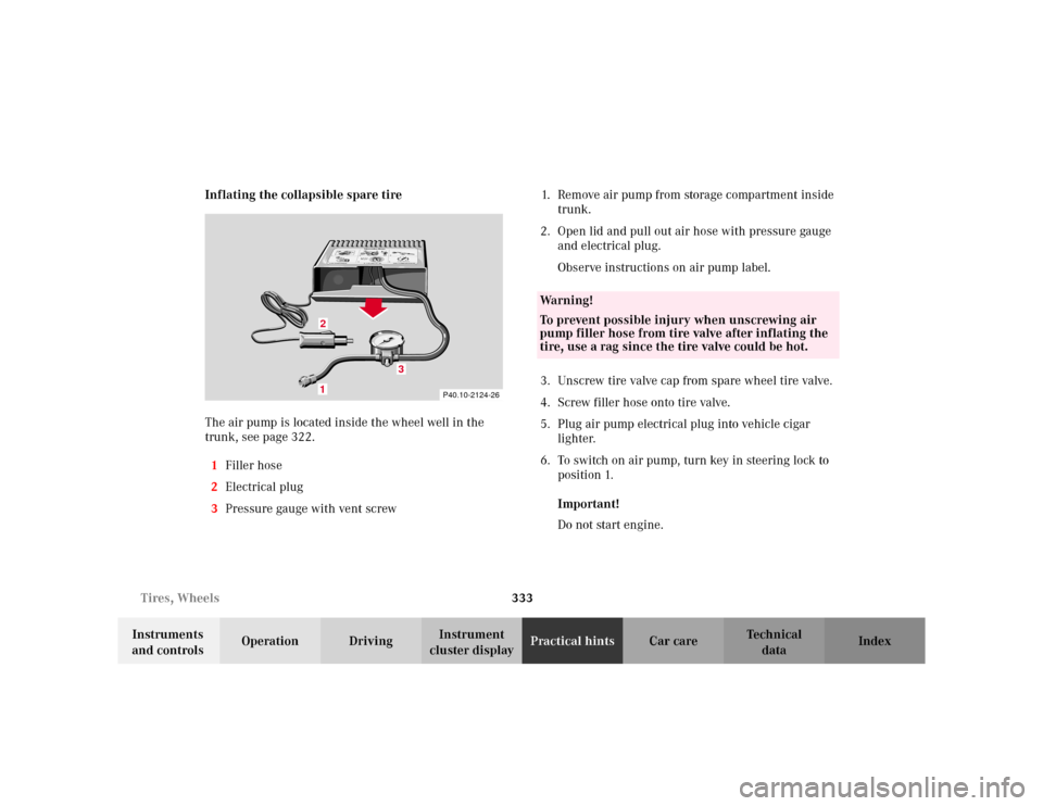
cluster displayPractical hintsCar care Index Inflating the collapsible spare tire
The air pump is located inside the wheel well in the
trunk, see page 322.
1Filler hose
2Electrical plug
3Pressure gauge with vent screw1. Remove air pump from storage compartment inside
trunk.
2. Open lid and pull out air hose with pressure gauge
and electrical plug.
Observe instructions on air pump label.
3. Unscrew tire valve cap from spare wheel tire valve.
4. Screw filler hose onto tire valve.
5. Plug air pump electrical plug into vehicle cigar
lighter.
6. To switch on air pump, turn key in steering lock to
position 1.
Important!
Do not start engine.
P40.10-2124-26
1
0
45 6max. 6 min
A 170 584 01 38 AIR COMPRESSOR 23
Mercedes-Benz
2
3
2 1
1
2,5 bar
36 psi1
0 23
4
5
620PSI
BAR40
60
80
LUFTPRESSER12
12
3
Wa r n i n g !
To prevent possible injury when unscrewing air
pump filler hose from tire valve after inflating the
tire, use a rag since the tire valve could be hot.
Page 357 of 399
354 Fuel filler flap, manual release
Te ch n i c a l
data Instruments
and controlsOperation DrivingInstrument
cluster displayPractical hintsCar care Index
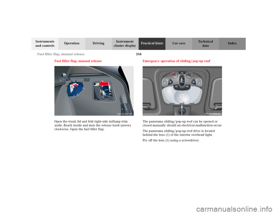
Fuel filler flap, manual release
Open the trunk lid and fold right-side taillamp trim
aside. Reach inside and turn the release knob (arrow)
clockwise. Open the fuel filler flap.Emergency operation of sliding / pop-up roof
The panorama sliding / pop-up roof can be opened or
closed manually should an electrical malfunction occur.
The panorama sliding / pop-up roof drive is located
behind the lens (1) of the interior overhead light.
Pry off the lens (1) using a screwdriver.
P47.25-2031-26