parking brake MERCEDES-BENZ C240 2002 W203 Owner's Guide
[x] Cancel search | Manufacturer: MERCEDES-BENZ, Model Year: 2002, Model line: C240, Model: MERCEDES-BENZ C240 2002 W203Pages: 406
Page 331 of 406
328 Tires, Wheels
Te ch n i c a l
data Instruments
and controlsOperation DrivingInstrument
cluster displayPractical hintsCar care Index
Wheels
Replace rims or tires with the same designation,
manufacturer and type as shown on the original part.
See your authorized Mercedes-Benz Center for further
information.
See your authorized Mercedes-Benz Center for
information on tested and recommended rims and tires
for summer and winter operation. They can also offer
advice concerning tire service and purchase.
Tire replacement
Front and rear tires should be replaced in sets. Rims
and tires must be of the correct size and type. For
dimensions, see “Technical Data”.
We recommend that you break in new tires for
approximately 60 miles (100 km) at moderate speed.
Wa r n i n g !
The jack is designed exclusively for jacking up the
vehi c le a t the j ack take-up b ra ckets b ui lt i nto eit her
side of the vehicle. To help avoid personal injury,
use the jack only to lift the vehicle during a wheel
change. Never get beneath the vehicle while it is
supported by the jack. Keep hands and feet away
from the area under the lifted vehicle. Always
firmly set parking brake and block wheels before
raising vehicle with jack.Do n ot d is engage parki n g brake w hil e t he vehi c le i s
raised. Be certain that the jack is always vertical
when in use, especially on hills. Always try to use
the jack on level surface. Be sure that the jack arm
is fully seated in the jack take-up bracket. Always
lower the vehicle onto sufficient capacity
jackstands before working under the vehicle.
OM_203.book Seite 328 Donnerstag, 31. Mai 2001 11:57 11
Page 334 of 406
331 Tires, Wheels
Te ch n i c a l
data Instruments
and controlsOperation DrivingInstrument
cluster displayPractical hintsCar care Index Changing wheelsMove vehicle to a level area which is a safe distance
from the roadway.
1. Set parking brake and turn on hazard warning
flasher.
2. Move selector lever to position “P” and turn off
engine (manual transmission to 1st or reverse gear).
3. Prevent vehicle from rolling away by blocking
wheels with wheel chocks (not supplied with
vehicle) or sizable wood block or stone. When
changing a wheel on a hill, place chocks on the
downhill side blocking both wheels of the other
axle. On an level road, place one chock in front of
and one behind the wheel that is diagonally
opposite to the wheel being changed.
Wa r n i n g !
The jack is designed exclusively for jacking up the
vehi c le a t the j ack take-up b ra ckets b ui lt i nto eit her
side of the vehicle. To help avoid personal injury,
use the jack only to lift the vehicle during a wheel
change. Never get beneath the vehicle while it is
supported by the jack. Keep hands and feet away
from the area under the lifted vehicle. Always
firmly set parking brake and block wheels before
raising vehicle with jack.
Do n ot d is engage parki n g brake w hil e t he vehi c le i s
raised. Be certain that the jack is always vertical
when in use, especially on hills. Always try to use
the jack on level surface. Be sure that the jack arm
is fully seated in the jack take-up bracket. Always
lower the vehicle onto sufficient capacity
jackstands before working under the vehicle.
OM_203.book Seite 331 Donnerstag, 31. Mai 2001 11:57 11
Page 341 of 406
338 Tires, Wheels
Te ch n i c a l
data Instruments
and controlsOperation DrivingInstrument
cluster displayPractical hintsCar care Index
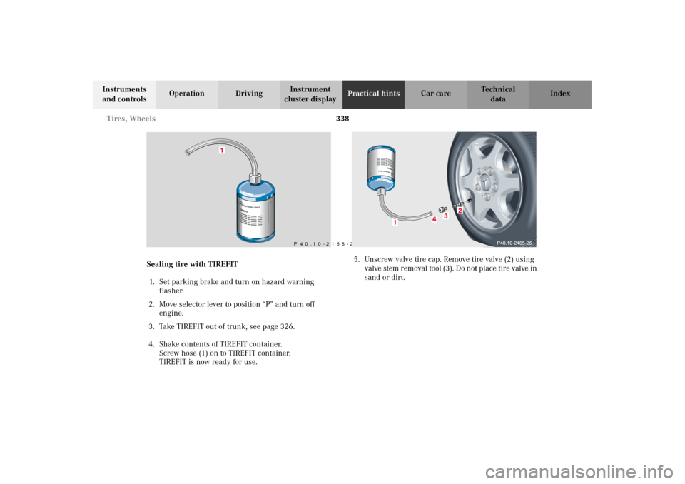
Sealing tire with TIREFIT
1. Set parking brake and turn on hazard warning
flasher.
2. Move selector lever to position “P” and turn off
engine.
3. Take TIREFIT out of trunk, see page 326.
4. Shake contents of TIREFIT container.
Screw hose (1) on to TIREFIT container.
TIREFIT is now ready for use.5. Unscrew valve tire cap. Remove tire valve (2) using
valve stem r emoval tool (3 ). Do n ot p lace tir e valve in
sand or dirt.
1
P 40.10-2158-26
OM_203.book Seite 338 Donnerstag, 31. Mai 2001 11:57 11
Page 349 of 406
346 Jump starting
Te ch n i c a l
data Instruments
and controlsOperation DrivingInstrument
cluster displayPractical hintsCar care Index
Proceed as follows:
1. Position the vehicle with the charged battery so that
the jumper cables will reach, but never let the
vehicles touch. Make sure the jumper cables do not
have loose or missing insulation.
2. On both vehicles:
•Turn off engine and all lights and accessories,
except hazard warning flashers or work lights.
•Apply parking brake and shift selector lever to
position “P” (manual transmission to Neutral).
Important!
3. Clamp one end of the first jumper cable to the
positive (+) under hood terminal of the discharged
battery and the other end to the positive (+) terminal
of the charged battery. Make sure the cable clamps
do not touch any other metal parts.
4. Clamp one end of the second jumper cable to the
grounded negative (–) terminal of the charged
battery and the final connection to the negative (–)
under hood terminal of the disabled vehicle.Important!
5. Start engine of the vehicle with the charged battery
and run at high idle. Make sure the cables are not
on or near pulleys, fans, or other parts that move
when the engine is started. Allow the discharged
battery to charge for a few minutes. Start engine of
the disabled vehicle in the usual manner.
6. After the engine has started, remove jumper cables
by exactly reversing the above installation
sequence, starting with the last connection made
first. When removing each clamp, make sure that it
does not touch any other metal while the other end
is still attached.
Note:
If engine does not run after several unsuccessful
starting attempts, have it checked at the nearest
authorized Mercedes-Benz Center.
Excessive unburned fuel may damage the catalytic
converter.
OM_203.book Seite 346 Donnerstag, 31. Mai 2001 11:57 11
Page 397 of 406
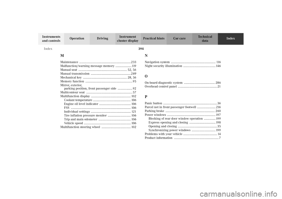
394 Index
Te ch n i c a l
data Instruments
and controlsOperation DrivingInstrument
cluster displayPractical hints Car careIndex
MMaintenance ...................................................................233
Malfunction/warning message memory .....................119
Manual seat ............................................................... 52, 56
Manual transmission ....................................................249
Mechanical key ......................................................... 28, 36
Memory function ............................................................. 95
Mirror, exterior,
parking position, front passenger side ................... 92
Multicontour seat ............................................................ 57
Multifunction display .................................................... 102
Coolant temperature ................................................. 106
Engine oil level indicator ......................................... 106
FSS .............................................................................. 106
Individual settings .................................................... 121
Tire inflation pressure monitor .............................. 106
Trip and main odometer .......................................... 106
Vehicle speed ............................................................. 106
Multifunction steering wheel ...................................... 102
NNavigation system .......................................................... 116
Night security illumination .......................................... 146OOn-board diagnostic system ........................................ 286
Overhead control panel ................................................... 21PPanic button ......................................................................36
Parcel net in front passenger footwell ........................ 216
Parking brake ................................................................ 260
Power windows ............................................................... 197
Blocking of rear door window operation ............... 199
Express opening and closing .................................. 198
Opening and closing ...................................................35
Synchronizing power windows ............................... 199
Problems with your vehicle ............................................ 14
Product information .......................................................... 7
OM_203.book Seite 394 Donnerstag, 31. Mai 2001 11:57 11