brake MERCEDES-BENZ CL COUPE 2009 Manual Online
[x] Cancel search | Manufacturer: MERCEDES-BENZ, Model Year: 2009, Model line: CL COUPE, Model: MERCEDES-BENZ CL COUPE 2009Pages: 421, PDF Size: 10.78 MB
Page 354 of 421
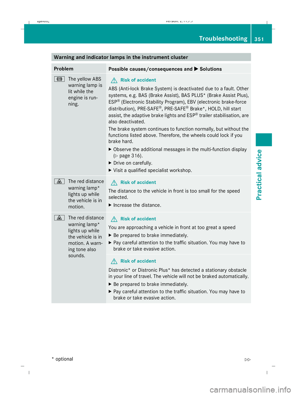
Warning and indicator lamps in the instrument cluster
Problem
Possible causes/consequences and
X
X Solutions !
The yellow ABS
warning lamp is
lit while the
engine is run-
ning. G
Risk of accident
ABS (Anti-lock Brake System) is deactivated due to a fault. Other
systems, e.g. BAS (Brake Assist), BAS PLUS* (Brake Assist Plus),
ESP ®
(Electronic Stability Program), EBV (electronic brake-force
distribution), PRE-SAFE ®
, PRE-SAFE ®
Brake*, HOLD, hill start
assist, the adaptive brake lights and ESP ®
trailer stabilisation, are
also deactivated.
The brake system continues to function normally, but without the
functions listed above. Therefore, the wheels could lock if you
brake hard.
X Observe the additional messages in the multi-function display
(Y page 316).
X Drive on carefully.
X Visit a qualified specialist workshop. ·
The red distance
warning lamp*
lights up while
the vehicle is in
motion. G
Risk of accident
The distance to the vehicle in front is too small for the speed
selected.
X Increase the distance. ·
The red distance
warning lamp*
lights up while
the vehicle is in
motion. A warn-
ing tone also
sounds. G
Risk of accident
You are approaching a vehicle in front at too great a speed
X Be prepared to brake immediately.
X Pay careful attention to the traffic situation. You may have to
brake or take evasive action. G
Risk of accident
Distronic* or Distronic Plus* has detected a stationary obstacle
in your line of travel. The vehicle will not be braked automatically.
X Be prepared to brake immediately.
X Pay careful attention to the traffic situation. You may have to
brake or take evasive action. Troubleshooting
351Practical advice
* optional
216_AKB; 2; 3, en-GB
bjanott,
Version: 2.11.7.7 2009-02-27T14:54:17+01:00 - Seite 351 Z
Dateiname: 6515230602_buchblock.pdf; erzeugt am 04. Mar 2009 11:16:40; WK
Page 355 of 421
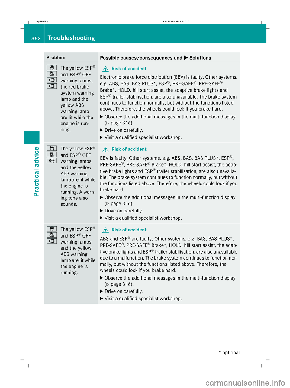
Problem
Possible causes/consequences and
X XSolutions ÷
å
J
!
The yellow ESP
®
and ESP ®
OFF
warning lamps,
the red brake
system warning
lamp and the
yellow ABS
warning lamp
are lit while the
engine is run-
ning. G
Risk of accident
Electronic brake force distribution (EBV) is faulty. Other systems,
e.g. ABS, BAS, BAS PLUS*, ESP ®
, PRE-SAFE ®
, PRE-SAFE ®
Brake*, HOLD, hill start assist, the adaptive brake lights and
ESP ®
trailer stabilisation, are also unavailable. The brake system
continues to function normally, but without the functions listed
above. Therefore, the wheels could lock if you brake hard.
X Observe the additional messages in the multi-function display
(Y page 316).
X Drive on carefully.
X Visit a qualified specialist workshop. ÷
å
!
The yellow ESP
®
and ESP ®
OFF
warning lamps
and the yellow
ABS warning
lamp are lit while
the engine is
running. A warn-
ing tone also
sounds. G
Risk of accident
EBV is faulty. Other systems, e.g. ABS, BAS, BAS PLUS*, ESP ®
,
PRE-SAFE ®
, PRE-SAFE ®
Brake*, HOLD, hill start assist, the adap-
tive brake lights and ESP ®
trailer stabilisation, are also unavaila-
ble. The brake system continues to function normally, but without
the functions listed above. Therefore, the wheels could lock if you
brake hard.
X Observe the additional messages in the multi-function display
(Y page 316).
X Drive on carefully.
X Visit a qualified specialist workshop. ÷
å
!
The yellow ESP
®
and ESP ®
OFF
warning lamps
and the yellow
ABS warning
lamp are lit while
the engine is
running. G
Risk of accident
ABS and ESP ®
are faulty. Other systems, e.g. BAS, BAS PLUS*,
PRE-SAFE ®
, PRE-SAFE ®
Brake*, HOLD, hill start assist, the adap-
tive brake lights and ESP ®
trailer stabilisation, are also unavailable
due to a malfunction. The brake system continues to function nor-
mally, but without the functions listed above. Therefore, the
wheels could lock if you brake hard.
X Observe the additional messages in the multi-function display
(Y page 316).
X Drive on carefully.
X Visit a qualified specialist workshop. 352
TroubleshootingPractical advice
* optional
216_AKB; 2; 3, en-GB
bjanott,
Version: 2.11.7.7 2009-02-27T14:54:17+01:00 - Seite 352
Dateiname: 6515230602_buchblock.pdf; erzeugt am 04. Mar 2009 11:16:41; WK
Page 356 of 421
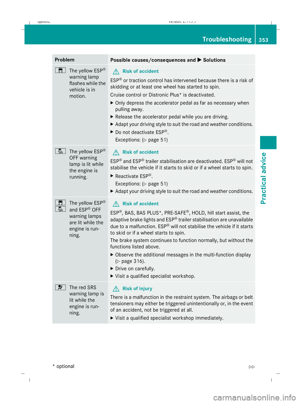
Problem
Possible causes/consequences and
X
X Solutions ÷
The yellow ESP ®
warning lamp
flashes while the
vehicle is in
motion. G
Risk of accident
ESP ®
or traction control has intervened because there is a risk of
skidding or at least one wheel has started to spin.
Cruise control or Distronic Plus* is deactivated.
X Only depress the accelerator pedal as far as necessary when
pulling away.
X Release the accelerator pedal while you are driving.
X Adapt your driving style to suit the road and weather conditions.
X Do not deactivate ESP ®
.
Exceptions: (Y page 51) å
The yellow ESP ®
OFF warning
lamp is lit while
the engine is
running. G
Risk of accident
ESP ®
and ESP ®
trailer stabilisation are deactivated. ESP ®
will not
stabilise the vehicle if it starts to skid or if a wheel starts to spin.
X Reactivate ESP ®
.
Exceptions: (Y page 51)
X Adapt your driving style to suit the road and weather conditions. ÷
å
The yellow ESP
®
and ESP ®
OFF
warning lamps
are lit while the
engine is run-
ning. G
Risk of accident
ESP ®
, BAS, BAS PLUS*, PRE-SAFE ®
, HOLD, hill start assist, the
adaptive brake lights and ESP ®
trailer stabilisation are unavailable
due to a malfunction. ESP ®
will not stabilise the vehicle if it starts
to skid or if a wheel starts to spin.
The brake system continues to function normally, but without the
functions listed above.
X Observe the additional messages in the multi-function display
(Y page 316).
X Drive on carefully.
X Visit a qualified specialist workshop. 6
The red SRS
warning lamp is
lit while the
engine is run-
ning. G
Risk of injury
There is a malfunction in the restraint system. The airbags or belt
tensioners may either be triggered unintentionally or, in the event
of an accident, not be triggered at all.
X Visit a qualified specialist workshop immediately. Troubleshooting
353Practical advice
* optional
216_AKB; 2; 3, en-GB
bjanott,
Version: 2.11.7.7 2009-02-27T14:54:17+01:00 - Seite 353 Z
Dateiname: 6515230602_buchblock.pdf; erzeugt am 04. Mar 2009 11:16:41; WK
Page 357 of 421
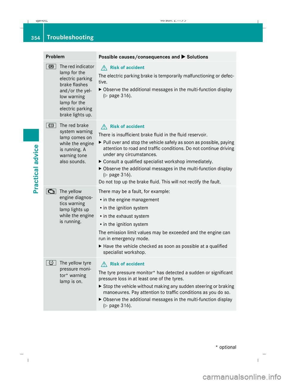
Problem
Possible causes/consequences and
X XSolutions !
The red indicator
lamp for the
electric parking
brake flashes
and/or the yel-
low warning
lamp for the
electric parking
brake lights up. G
Risk of accident
The electric parking brake is temporarily malfunctioning or defec-
tive.
X Observe the additional messages in the multi-function display
(Y page 316). J
The red brake
system warning
lamp comes on
while the engine
is running. A
warning tone
also sounds. G
Risk of accident
There is insufficient brake fluid in the fluid reservoir.
X Pull over and stop the vehicle safely as soon as possible, paying
attention to road and traffic conditions. Do not continue driving
under any circumstances.
X Consult a qualified specialist workshop immediately.
X Observe the additional messages in the multi-function display
(Y page 316).
Do not top up the brake fluid. This will not rectify the fault. ;
The yellow
engine diagnos-
tics warning
lamp lights up
while the engine
is running. There may be a fault, for example:
R
in the engine management
R in the ignition system
R in the exhaust system
R in the ignition system
The emission limit values may be exceeded and the engine can
run in emergency mode.
X Have the vehicle checked as soon as possible at a qualified
specialist workshop. h
The yellow tyre
pressure moni-
tor* warning
lamp is on. G
Risk of accident
The tyre pressure monitor* has detected a sudden or significant
pressure loss in at least one of the tyres.
X Stop the vehicle without making any sudden steering or braking
manoeuvres. Pay attention to traffic conditions as you do so.
X Observe the additional messages in the multi-function display
(Y page 316). 354
TroubleshootingPractical advice
* optional
216_AKB; 2; 3, en-GB
bjanott,
Version: 2.11.7.7 2009-02-27T14:54:17+01:00 - Seite 354
Dateiname: 6515230602_buchblock.pdf; erzeugt am 04. Mar 2009 11:16:41; WK
Page 359 of 421
Problem
Possible causes/consequences and
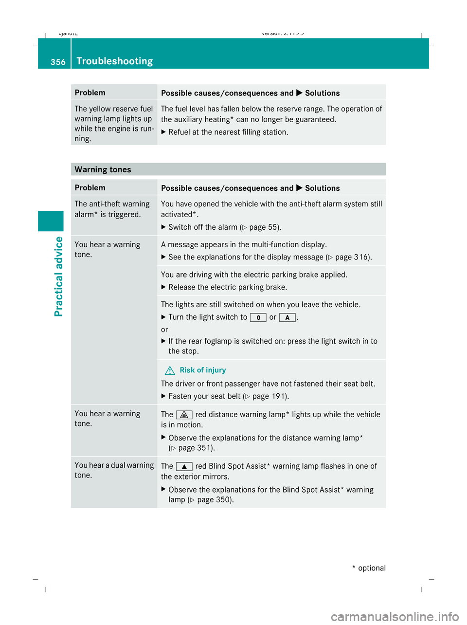
X XSolutions The yellow reserve fuel
warning lamp lights up
while the engine is run-
ning. The fuel level has fallen below the reserve range. The operation of
the auxiliary heating* can no longer be guaranteed.
X
Refuel at the nearest filling station. Warning tones
Problem
Possible causes/consequences and
X XSolutions The anti-theft warning
alarm* is triggered. You have opened the vehicle with the anti-theft alarm system still
activated*.
X
Switch off the alarm (Y page 55).You hear a warning
tone. A message appears in the multi-function display.
X
See the explanations for the display message (Y page 316).You are driving with the electric parking brake applied.
X
Release the electric parking brake. The lights are still switched on when you leave the vehicle.
X
Turn the light switch to $orc.
or
X If the rear foglamp is switched on: press the light switch in to
the stop. G
Risk of injury
The driver or front passenger have not fastened their seat belt.
X Fasten your seat belt (Y page 191).You hear a warning
tone.
The
· red distance warning lamp* lights up while the vehicle
is in motion.
X Observe the explanations for the distance warning lamp*
(Y page 351). You hear a dual warning
tone.
The
9 red Blind Spot Assist* warning lamp flashes in one of
the exterior mirrors.
X Observe the explanations for the Blind Spot Assist* warning
lamp (Y page 350). 356
TroubleshootingPractical advice
* optional
216_AKB; 2; 3, en-GB
bjanott,
Version: 2.11.7.7 2009-02-27T14:54:17+01:00 - Seite 356
Dateiname: 6515230602_buchblock.pdf; erzeugt am 04. Mar 2009 11:16:41; WK
Page 375 of 421
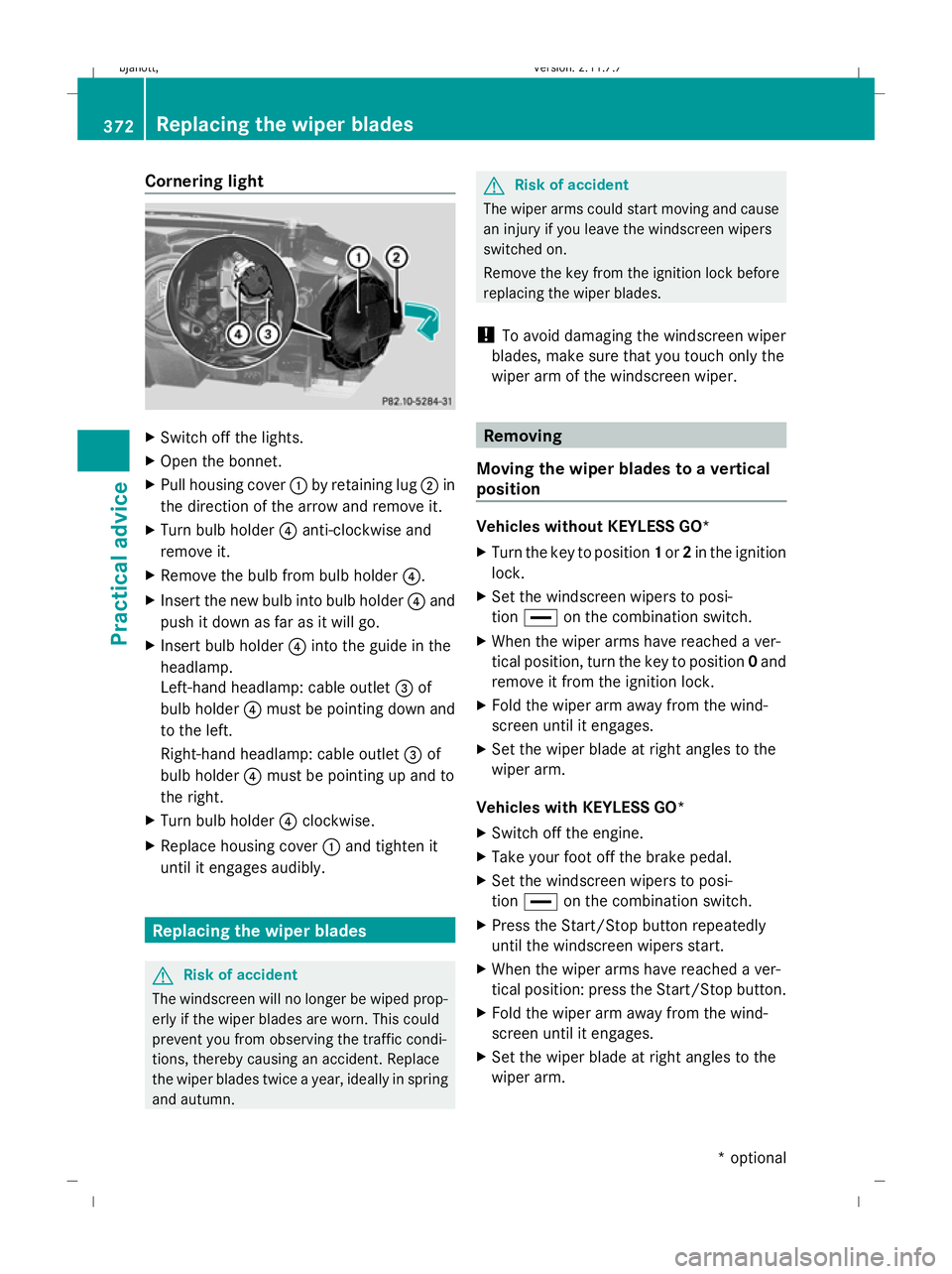
Cornering light
X
Switch off the lights.
X Open the bonnet.
X Pull housing cover :by retaining lug ;in
the direction of the arrow and remove it.
X Turn bulb holder ?anti-clockwise and
remove it.
X Remove the bulb from bulb holder ?.
X Insert the new bulb into bulb holder ?and
push it down as far as it will go.
X Insert bulb holder ?into the guide in the
headlamp.
Left-hand headlamp: cable outlet =of
bulb holder ?must be pointing down and
to the left.
Right-hand headlamp: cable outlet =of
bulb holder ?must be pointing up and to
the right.
X Turn bulb holder ?clockwise.
X Replace housing cover :and tighten it
until it engages audibly. Replacing the wiper blades
G
Risk of accident
The windscreen will no longer be wiped prop-
erly if the wiper blades are worn. This could
prevent you from observing the traffic condi-
tions, thereby causing an accident. Replace
the wiper blades twice a year, ideally in spring
and autumn. G
Risk of accident
The wiper arms could start moving and cause
an injury if you leave the windscreen wipers
switched on.
Remove the key from the ignition lock before
replacing the wiper blades.
! To avoid damaging the windscreen wiper
blades, make sure that you touch only the
wiper arm of the windscreen wiper. Removing
Moving the wiper blades to a vertical
position Vehicles without KEYLESS GO*
X
Turn the key to position 1or 2in the ignition
lock.
X Set the windscreen wipers to posi-
tion ° on the combination switch.
X When the wiper arms have reached a ver-
tical position, turn the key to position 0and
remove it from the ignition lock.
X Fold the wiper arm away from the wind-
screen until it engages.
X Set the wiper blade at right angles to the
wiper arm.
Vehicles with KEYLESS GO*
X Switch off the engine.
X Take your foot off the brake pedal.
X Set the windscreen wipers to posi-
tion ° on the combination switch.
X Press the Start/Stop button repeatedly
until the windscreen wipers start.
X When the wiper arms have reached a ver-
tical position: press the Start/Stop button.
X Fold the wiper arm away from the wind-
screen until it engages.
X Set the wiper blade at right angles to the
wiper arm. 372
Replacing the wiper bladesPractical advice
* optional
216_AKB; 2; 3, en-GB
bjanott
,V ersion: 2.11.7.7
2009-02-27T14:54:17+01:00 - Seite 372
Dateiname: 6515230602_buchblock.pdf; erzeugt am 04. Mar 2009 11:16:46; WK
Page 376 of 421

Removing the wiper blades
X
Remove the wiper blade from the retainer
on the wiper arm in the direction of the
arrow. Fitting
X Slide the new wiper blade into the retainer
on the wiper arm in the opposite direction
to the arrow.
X Turn the wiper blade parallel to the wiper
arm.
X Fold the wiper arm back onto the wind-
screen. Flat tyre
Flat tyre equipment variants
Your vehicle may be equipped with:
R a TIREFIT kit (Y page 315)
R a "Minispare" emergency spare
wheel* (Y page 315)
R a spare wheel* (Y page 316)
R the MOExtended run-flat sys-
tem* (Y page 381) Preparing the vehicle
i Vehicle preparation is not necessary on
vehicles with MOE tyres*. X
Stop the vehicle as far away as possible
from traffic on solid, non-slippery and level
ground.
X Switch on the hazard warning lamps.
X Engage the electric parking brake manually
(Y page 205).
X Move the DIRECT SELECT selector lever to
P.
X All occupants must get out of the vehicle.
Make sure that they are not endangered as
they get out of the vehicle.
X Make sure that no one is near the danger
area whilst a wheel is being changed. Any-
one who is not directly assisting in the
wheel change should, for example, stand
behind the barrier.
X Switch off the engine.
X Remove the key from the ignition lock.
X Get out of the vehicle.
X Close the driver’s door.
X Place the warning triangle (Y page 314) at
a suitable distance. Observe legal require-
ments. Using the TIREFIT kit
You can use the TIREFIT kit to seal small
punctures, particularly those in the tyre tread.
You can use TIREFIT at outside temperatures
down to -20 †. G
Risk of accident
In the following situations, your safety is at
particular risk and tyre sealant is unable to
provide breakdown assistance if:
R there are cuts or punctures in the tyre
greater than 4 mm
R the wheel rim is damaged
R you have driven at very low tyre pressures
or on a flat tyre
Do not drive any further. Consult a qualified
specialist workshop which has the necessary Flat tyre
373Practical advice
* optional
216_AKB; 2; 3, en-GB
bjanott,
Version: 2.11.7.7 2009-02-27T14:54:17+01:00 - Seite 373 Z
Dateiname: 6515230602_buchblock.pdf; erzeugt am 04. Mar 2009 11:16:47; WK
Page 383 of 421
X
Unscrew the uppermost wheel bolt com-
pletely.
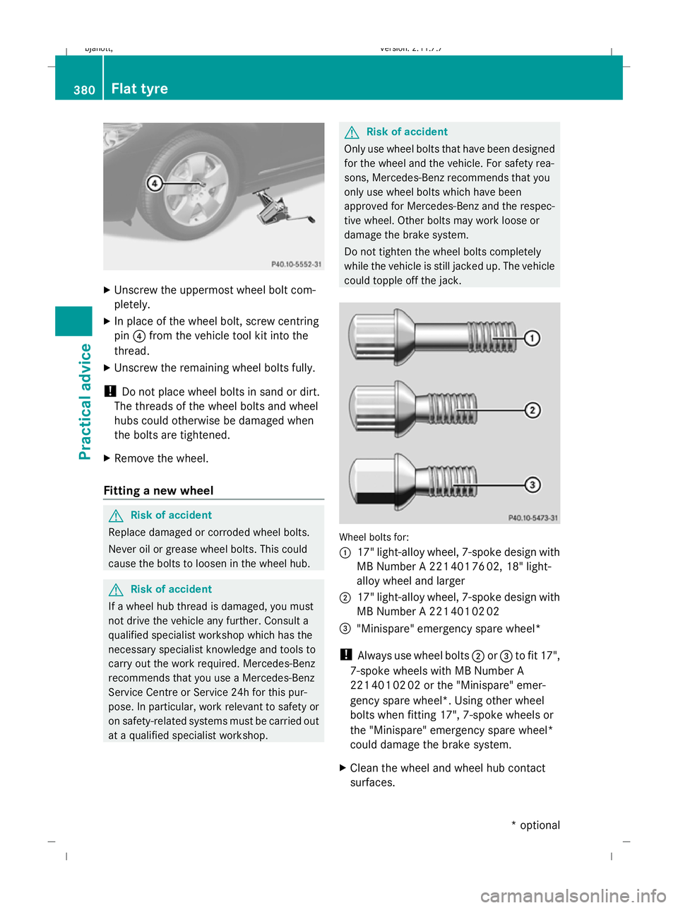
X In place of the wheel bolt, screw centring
pin ?from the vehicle tool kit into the
thread.
X Unscrew the remaining wheel bolts fully.
! Do not place wheel bolts in sand or dirt.
The threads of the wheel bolts and wheel
hubs could otherwise be damaged when
the bolts are tightened.
X Remove the wheel.
Fitting a new wheel G
Risk of accident
Replace damaged or corroded wheel bolts.
Never oil or grease wheel bolts. This could
cause the bolts to loosen in the wheel hub. G
Risk of accident
If a wheel hub thread is damaged, you must
not drive the vehicle any further. Consult a
qualified specialist workshop which has the
necessary specialist knowledge and tools to
carry out the work required. Mercedes-Benz
recommends that you use a Mercedes-Benz
Service Centre or Service 24h for this pur-
pose. In particular, work relevant to safety or
on safety-related systems must be carried out
at a qualified specialist workshop. G
Risk of accident
Only use wheel bolts that have been designed
for the wheel and the vehicle. For safety rea-
sons, Mercedes-Benz recommends that you
only use wheel bolts which have been
approved for Mercedes-Benz and the respec-
tive wheel. Other bolts may work loose or
damage the brake system.
Do not tighten the wheel bolts completely
while the vehicle is still jacked up. The vehicle
could topple off the jack. Wheel bolts for:
:
17" light-alloy wheel, 7-spoke design with
MB Number A 221 401 76 02, 18" light-
alloy wheel and larger
; 17" light-alloy wheel, 7-spoke design with
MB Number A 221 401 02 02
= "Minispare" emergency spare wheel*
! Always use wheel bolts ;or= to fit 17",
7-spoke wheels with MB Number A
221 401 02 02 or the "Minispare" emer-
gency spare wheel*. Using other wheel
bolts when fitting 17", 7-spoke wheels or
the "Minispare" emergency spare wheel*
could damage the brake system.
X Clean the wheel and wheel hub contact
surfaces. 380
Flat tyrePractical advice
* optional
216_AKB; 2; 3, en-GB
bjanott,
Version: 2.11.7.7 2009-02-27T14:54:17+01:00 - Seite 380
Dateiname: 6515230602_buchblock.pdf; erzeugt am 04. Mar 2009 11:16:50; WK
Page 387 of 421
ers. The vehicle will then use very little
energy, thus conserving the battery.
i If the battery is discharged, you must use
the emergency key element to unlock the
vehicle. Charging the battery
G
Risk of injury
Only charge the installed battery using a
Mercedes-Benz approved battery charger.
Otherwise, the vehicle's electronic system
may be damaged. Only charge the battery in
a well-ventilated area. As the battery is being
charged, gases can escape and generate
minor explosions. This could injure you and
other persons or cause damage to the paint-
work or acid corrosion on the vehicle.
You can obtain information about battery
chargers which allow the battery to be
charged while still installed from a qualified
specialist workshop, e.g. a Mercedes-Benz
Service Centre. G
Risk of injury
There is a risk of acid burns during the charg-
ing process due to the gases which escape
from the battery. Do not lean over the battery
during the charging process.
X Use the electric parking brake to secure the
vehicle and use the DIRECT SELECT lever
to set the transmission to P.
X Switch off all electrical consumers.
X Turn the key to position 0in the ignition
lock and remove it.
X Open the bonnet.
X Check that the breather hose is fitted and
that there is a cell cap on the opposite side
of the battery.
X Remove the cover from the positive termi-
nal.
X Connect the positive clamp of the battery
charger to the positive terminal of the bat-
tery. X
Connect the negative clamp of the battery
charger to the vehicle's earth point.
X Charge the battery. Observe the notes in
the operating instructions for your battery
charger.
X Disconnect the battery charger after charg-
ing.
X Attach the positive terminal cover.
X Close the bonnet. Jump-starting
If your vehicle's battery is discharged, the
engine can be jump-started from another
vehicle or from an external battery using jump
leads.
Observe the following points:
R jump-starting may only be performed when
the engine and catalytic converter are cold.
R do not start the engine if the battery is fro-
zen. Let the battery thaw first.
R jump-starting may only be performed from
batteries with a nominal voltage of 12 V.
R only use jump leads which have a sufficient
cross-section and insulated terminal
clamps.
i Jump leads and further information about
jump-starting can be obtained from any
Mercedes-Benz Service Centre.
! Avoid repeated and lengthy starting
attempts.
Never start the vehicle using a rapid battery
charger. G
Risk of injury
There is a risk of acid burns when jump-start-
ing a vehicle due to the gases which escape
from the battery. Do not lean over the battery
while the engine is being jump-started. 384
BatteryPractical advice
216_AKB; 2; 3, en-GB
bjanott,
Version: 2.11.7.7 2009-02-27T14:54:17+01:00 - Seite 384
Dateiname: 6515230602_buchblock.pdf; erzeugt am 04. Mar 2009 11:16:52; WK
Page 388 of 421
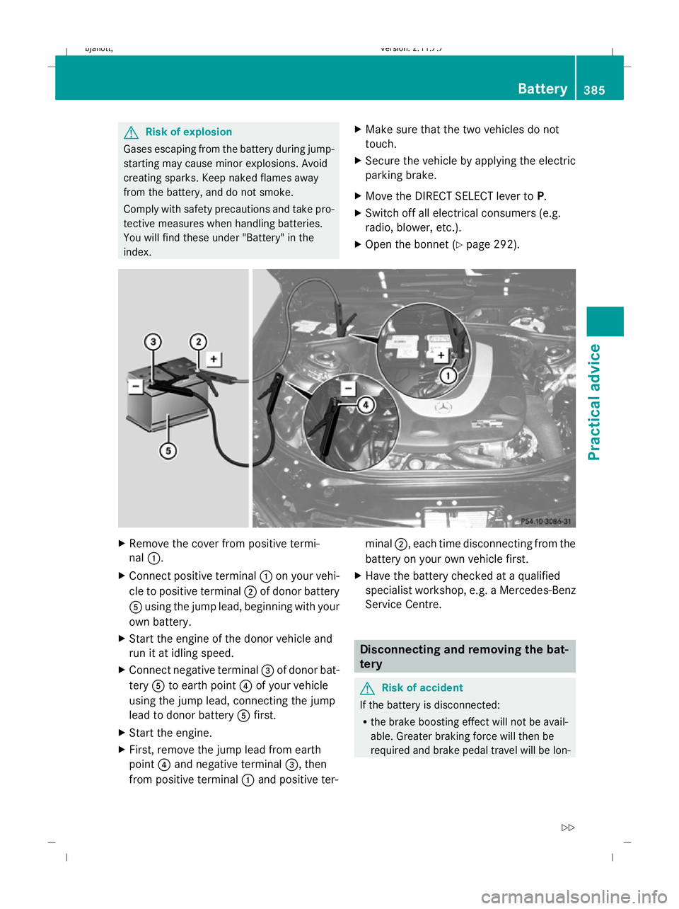
G
Risk of explosion
Gases escaping from the battery during jump-
starting may cause minor explosions. Avoid
creating sparks. Keep naked flames away
from the battery, and do not smoke.
Comply with safety precautions and take pro-
tective measures when handling batteries.
You will find these under "Battery" in the
index. X
Make sure that the two vehicles do not
touch.
X Secure the vehicle by applying the electric
parking brake.
X Move the DIRECT SELECT lever to P.
X Switch off all electrical consumers (e.g.
radio, blower, etc.).
X Open the bonnet (Y page 292). X
Remove the cover from positive termi-
nal :.
X Connect positive terminal :on your vehi-
cle to positive terminal ;of donor battery
A using the jump lead, beginning with your
own battery.
X Start the engine of the donor vehicle and
run it at idling speed.
X Connect negative terminal =of donor bat-
tery Ato earth point ?of your vehicle
using the jump lead, connecting the jump
lead to donor battery Afirst.
X Start the engine.
X First, remove the jump lead from earth
point ?and negative terminal =, then
from positive terminal :and positive ter- minal
;, each time disconnecting from the
battery on your own vehicle first.
X Have the battery checked at a qualified
specialist workshop, e.g. a Mercedes-Benz
Service Centre. Disconnecting and removing the bat-
tery
G
Risk of accident
If the battery is disconnected:
R the brake boosting effect will not be avail-
able. Greater braking force will then be
required and brake pedal travel will be lon- Battery
385Practical advice
216_AKB; 2; 3, en-GB
bjanott, Version: 2.11.7.7 2009-02-27T14:54:17+01:00 - Seite 385 Z
Dateiname: 6515230602_buchblock.pdf; erzeugt am 04. Mar 2009 11:16:52; WK