park assist MERCEDES-BENZ CL500 2001 C215 Owner's Manual
[x] Cancel search | Manufacturer: MERCEDES-BENZ, Model Year: 2001, Model line: CL500, Model: MERCEDES-BENZ CL500 2001 C215Pages: 424, PDF Size: 27.87 MB
Page 6 of 424

3 ContentsCoat hooks ...................................... 192
Cup holder ...................................... 193
Ashtrays .......................................... 196
Lighter ............................................. 198
Parcel net in trunk ........................ 199
Cargo tie-down hooks ....................200
Parcel net in front
passenger footwell ....................200
Telephone, general ........................ 201
Garage door opener .......................202
Infrared reflecting windshield ....206
DrivingControl and operation of radio
transmitters ...............................208
The first 1 000 miles
(1 500 km) .................................209
Maintenance ...................................209
Tele Aid ........................................... 210
Catalytic converter ........................220
Emission control ............................221
Starter switch .................................222
Starter switch – KEYLESS-GO ......224Starting and turning off
the engine .................................. 227
Automatic transmission ............... 229
Parking brake ................................ 238
Driving instructions ...................... 239
Drive sensibly – save fuel ........ 239
Drinking and driving ................ 239
Pedals .......................................... 240
Power assistance ........................ 240
Brakes .......................................... 240
Driving off ................................... 241
Parking ........................................ 242
Tires ............................................. 243
Snow chains ............................... 245
Winter driving instructions ..... 246
Deep water .................................. 248
Passenger compartment ........... 248
Traveling abroad ........................ 249
Cruise control ................................ 250
Distronic (DTR) .............................. 253
Brake assist system
(BAS) .......................................... 268
Antilock brake system
(ABS) .......................................... 269Electronic stability program
(ESP) ........................................... 271
Active body control (ABC) ............275
Level control system ...................... 276
Parking assist (Parktronic) ..........279
What you should know
at the gas station .......................284
Check regularly
and before a long trip ...............287
Instrument cluster displayMalfunction and indicator
lamps in the
instrument cluster ....................290
On-board diagnostic system .....290
Check engine malfunction
indicator lamp .............................290
Brake warning lamp ..................292
Supplemental restraint
system (SRS)
indicator lamp .............................293
Fuel reserve warning .................293
ABS malfunction
indicator lamp .............................294
Page 7 of 424

4 Contents
Electronic stability program
(ESP) — warning lamp ...............295
Distronic (DTR) —
warning lamp ..............................295
Seat belt nonusage
warning lamp ..............................296
Malfunction and indicator
lamp in the center console ......296
AIRBAG OFF indicator lamp .....296
Malfunction and
warning messages in the
multifunction display ...............297
DISPLAY DEFECTIVE
(engine control unit) ..................298
DISPLAY DEFECTIVE
(several systems) ........................298
BATTERY /ALTERNATOR ..........299
ENTRANCE POSITION ..............300
BRAKE ASSIST ...........................300
BRAKE LINING WEAR .............. 301
BRAKE FLUID ............................. 301
PARKING BRAKE .......................302
TRUNK OPEN .............................302ELEC. STABIL. PROG.
(Electronic stability
program) ..................................... 303
COOLANT (coolant level) ......... 304
COOLANT
(coolant temperature) ............... 305
LIGHTING SYSTEM ................... 306
LIGHT SENSOR .......................... 308
SEAT BELT SYSTEM .................. 308
TELEPHONE – FUNCTION ....... 309
CRUISE CONTROL ..................... 309
ACTIVE BO DY CO NTROL
(ABC) ............................................ 310
TIRE PRESSURE .........................312
ENGINE OIL LEVEL .................... 314
SEAT BACKREST ......................... 315
KEY ...............................................316
DOOR ............................................ 316
HOOD ............................................ 317
TELE AID ......................................317
ENGINE OIL LEVEL .................... 318
WASHER FLUID ..........................319
LIGHT SENSOR .......................... 320
DISTRONIC (DTR) ...................... 321
Practical hintsFirst aid kit .....................................324
Fuses ................................................325
Shelf below rear window ..............327
Hood .................................................328
Checking engine oil level ............. 331
Automatic transmission
fluid level ...................................332
Active b od y control
(ABC) fluid level ........................332
Coolant level ...................................333
Adding coolant ...........................333
Windshield and headlamp
washer system ...........................334
Windshield and headlamp
washer fluid mixing ratio .........334
Spare wheel, vehicle tools,
storage compartment ................335
Jack ...................................................336
Wheels .............................................337
Tire Replacement .......................337
Rotating wheels ..........................338
Spare wheel ....................................338
Page 27 of 424
24 Instruments and controls
Te ch n ica l
data Instruments
and controlsOperation DrivingInstrument
cluster displayPractical hints Car care Index
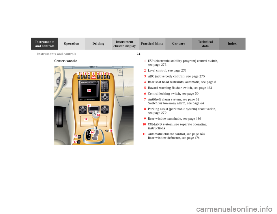
Center console1ESP (electronic stability program) control switch,
seepage273
2Level control, see page 276
3ABC (active body control), see page 275
4Rear seat head restraints, automatic, see page 81
5Hazard warning flasher switch, see page 163
6Central locking switch, see page 50
7Antitheft alarm system, see page 62
Switch for tow-away alarm, see page 64
8Parking assist (parktronic system) deactivation,
seepage279
9Rear window sunshade, see page 186
10COMAND system, see separate operating
instructions
11Automatic climate control, see page 164
Rear window defroster, see page 176
Page 111 of 424
108 Rear view mirrors
Te ch n ica l
data Instruments
and controlsOperationDrivingInstrument
cluster displayPractical hints Car care Index
Parking position
The passenger side exterior mirror can be adjusted and
programmed to assist the driver during parking
maneuvers (e.g. to observe the curb or other objects
close to the vehicle).
With the electronic key in starter switch position 2, and
the exterior rear view mirror switch in the passenger
side position, the passenger side mirror will be turned
downward when placing the gear selector lever in “R”
reverse.
The mirror position can now be adjusted as desired.
At speeds above approx. 6 mph (10 km/h), upon shifting
gear selector lever from “R” Reverse, or upon pressing
the driver’s side mirror button (1), the passenger side
mirror will return to its previous position.To store passenger mirror parking position:
1. Turn electronic key to starter switch position 1 or 2.
The vehicle must be stationary.
2. Select passenger side mirror& and adjust the
mirror to view the curb.
3. Push the memory button “M” (4).
4. Within 3 seconds push bottom of adjustment
button (3).
The mirror should not move.
Repeat the memory procedure if the mirror moves.
5. Select driver side mirror. The passenger side mirror
will return to its previous position.
Note:
One stored parking position is available for each of the
two electronic main keys or each of the KEYLESS-GO-
cards (vehicles with KEYLESS-GO).
Page 212 of 424
207 Contents - Driving
Te ch n ica l
data Instruments
and controlsOperationDrivingInstrument
cluster displayPractical hints Car care Index
DrivingControl and operation of radio
transmitters ...............................208
The first 1 000 miles
(1 500 km) .................................209
Maintenance ...................................209
Tele Aid ........................................... 210
Catalytic converter ........................220
Emission control ............................221
Starter switch .................................222
Starter switch – KEYLESS-GO ......224
Starting and turning off
the engine ..................................227
Automatic transmission ...............229
Parking brake .................................238Driving instructions ...................... 239
Drive sensibly – save fuel ........ 239
Drinking and driving ................ 239
Pedals .......................................... 240
Power assistance ........................ 240
Brakes .......................................... 240
Driving off ................................... 241
Parking ........................................ 242
Tires ............................................. 243
Snow chains ............................... 245
Winter driving instructions ..... 246
Deep water .................................. 248
Passenger compartment ........... 248
Traveling abroad ........................ 249
Cruise control ................................ 250Distronic (DTR) ..............................253
Brake assist system
(BAS) ...........................................268
Antilock brake system
(ABS) ...........................................269
Electronic stability program
(ESP) ........................................... 271
Active body control (ABC) ............275
Level control system ...................... 276
Parking assist (Parktronic) ..........279
What you should know
at the gas station .......................284
Check regularly
and before a long trip ...............287
Page 222 of 424
217 Tele Aid
Te ch n ica l
data Instruments
and controlsOperationDrivingInstrument
cluster displayPractical hints Car care Index During this time you will hear a chirp and voice contact
will be interrupted. Voice contact will resume once the
retransmission is completed. Once a call is concluded, a
chirp will be heard and the appropriate indicator lamp
will stop flashing. The COMAND system operation will
resume.
Important!
If the indicator lamp continues to flash or the system
does not reset, contact the Response Center at
1-800-756-9018 (in the USA) or 1-888-923-8367 (in
Canada), or Mercedes-Benz Client Assistance at
1-800-FOR-MERCedes (1-800-367-6372) in the USA or
Customer Service at 1-800-387-0100 in Canada.Notes:
The indicator lamp in the respective button flashes until
the call is concluded. Calls can only be terminated by a
Response Center or Client Assistance Center
representative except Roadside Assistance and
Information calls, which can also be terminated by
pressing ìbutton on the multifunction steering
wheel.
When a Tele Aid call has been initiated, the COMAND
system audio is muted and the selected mode (radio,
tape or CD) pauses. The optional cellular phone (if
installed) switches off. If you must use this phone, the
vehicle must be parked. Disconnect the coiled cord and
place the call. The navigation system (if engaged) will
continue to run. The display in the instrument cluster is
available for use and spoken commands are only
available by pressing the RPT button on the COMAND
unit. A pop-up window will appear in the COMAND
display to indicate that a Tele Aid call is in progress.
Page 245 of 424
240 Driving instructions
Te ch n ica l
data Instruments
and controlsOperationDrivingInstrument
cluster displayPractical hints Car care Index
Pedals
Power assistanceBrakes
The condition of the parking brake system is checked
each time the vehicle is in the shop for the required
maintenance service.
If the parking brake is released and the brake warning
lamp in the instrument cluster stays on, the brake f luid
level in the reservoir is too low.
Brake pad wear or a leak in the system may be the
reason for low brake f luid in the reservoir.
Wa r n i n g !
Keep driver’s foot area clear at all times. Objects
stored in this area may impair pedal movement.Wa r n i n g !
When the engine is not running, the brake and
steering systems are without power assistance.
Under these circumstances, a much greater effort is
necessary to stop or steer the vehicle.
Wa r n i n g !
After driving in heavy rain for some time without
applying the brakes or through water deep enough
to wet brake components, the first braking action
may be somewhat reduced and increased pedal
pressure may be necessary to obtain expected
braking effect. Be sure to maintain a safe distance
from vehicles in front.Resting your foot on the brake pedal will cause
excessive and premature wear of the brake pads.It can also result in the brakes overheating thereby
significantly reducing their effectiveness. It may
not be possible to stop the vehicle in sufficient time
to avoid an accident.
Page 284 of 424
279 Parking system
Te ch n ica l
data Instruments
and controlsOperationDrivingInstrument
cluster displayPractical hints Car care Index Parking assist (Parktronic)
The Parktronic system assists the driver during parking
maneuvers. It visually and audibly indicates the relative
distance between the vehicle and an obstacle.
The front area of the vehicle is monitored when driving
forward. When reversing or with the gear selector lever
in position “N”, the front as well as the rear areas are
monitored.
With the electronic key in starter switch position 2,
Parktronic engages automatically at speeds up to
approximately 10 mph (15 km/h) and deactivates during
higher speeds.
Parktronic can be switched off by a control switch
located in the center console. It engages automatically
again when starting the engine.
See page 283 for parktronic switch.
Wa r n i n g !
Parktronic is a supplemental system. It is not
intended to nor does it replace the need for extreme
care. The responsibility during parking and other
critical maneuvers rests always with the driver.Special attention must be paid to objects having
smooth surfaces or low silhouettes (e.g. trailer
couplings, painted posts, or street curbs). Such
objects may not be detected by the system and can
damage the vehicle.The operational function of the Parktronic can be
affected by dirty sensors, especially at times of
snow and ice. See page 378 for notes on cleaning
the parktronic system sensors.Interference caused by other ultrasonic signals
(e.g. working jackhammers or the air brakes of
trucks) can cause the system to send erratic
indications, and should be taken into
consideration.
Page 295 of 424
289 Contents - Instrument cluster display
Te ch n ica l
data Instruments
and controlsOperation DrivingInstrument
cluster displayPractical hints Car care Index
Instrument cluster displayMalfunction and indicator
lamps in the
instrument cluster ....................290
On-board diagnostic system .....290
Check engine malfunction
indicator lamp .............................290
Brake warning lamp ..................292
Supplemental restraint
system (SRS)
indicator lamp .............................293
Fuel reserve warning .................293
ABS malfunction
indicator lamp .............................294
Electronic stability program
(ESP) — warning lamp ...............295
Distronic (DTR) —
warning lamp ..............................295
Seat belt nonusage
warning lamp ..............................296Malfunction and indicator
lamp in the center console ...... 296
AIRBAG OFF indicator lamp .... 296
Malfunction and
warning messages in the
multifunction display .............. 297
DISPLAY DEFECTIVE
(engine control unit) ................. 298
DISPLAY DEFECTIVE
(several systems) ....................... 298
BATTERY /ALTERNATOR ......... 299
ENTRANCE POSITION .............. 300
BRAKE ASSIST ........................... 300
BRAKE LINING WEAR .............. 301
BRAKE FLUID ............................ 301
PARKING BRAKE ....................... 302
TRUNK OPEN ............................. 302
ELEC. STABIL. PROG.
(Electronic stability
program) ..................................... 303
COOLANT (coolant level) ......... 304COOLANT
(coolant temperature) ................305
LIGHTING SYSTEM ....................306
LIGHT SENSOR ...........................308
SEAT BELT SYSTEM ...................308
TELEPHONE – FUNCTION .......309
CRUISE CONTROL .....................309
ACTIV E BO DY CO NTROL
(ABC) ............................................ 310
TIRE PRESSURE ......................... 312
ENGINE OIL LEVEL ................... 314
SEAT BACKREST ........................ 315
KEY ............................................... 316
DOOR ........................................... 316
HOOD ........................................... 317
TELE AID ..................................... 317
ENGINE OIL LEVEL ................... 318
WASHER FLUID ......................... 319
LIGHT SENSOR ...........................320
DISTRONIC (DTR) ...................... 321
Page 300 of 424
294 Malfunction and indicator lamps
Te ch n ica l
data Instruments
and controlsOperation DrivingInstrument
cluster displayPractical hints Car care Index
ABS malfunction indicator lamp
The ABS malfunction indicator lamp in the
instrument cluster comes on with the
electronic key in starter switch position 2
and should go out with the engine running.
When the ABS malfunction indicator lamp symbol and
warning in the instrument cluster remains illuminated
while the engine is running, it indicates that the ABS
has detected a malfunction and has switched off. In this
case, the brake system functions in the usual manner,
but without antilock assistance.
A malfunctioning ABS control unit can possibly affect
the operation of other systems (e.g. Parktronic,
Navigation, Automatic transmission). Be guided
a ccord ingly w ith respect to t he u se of th ose systems and
have the system checked at your authorized
Mercedes-Benz Center as soon as possible.With the ABS malfunctioning, the BAS and ESP are also
switched off. The malfunction indicator lamps and
malfunction messages in the multifunction display
come on with the engine running.
If the charging voltage falls below 10 volts, the
malfunction indicator lamp comes on and the ABS is
sw itched of f. Wh en t he voltage is a bove th is value a gain,
the malfunction indicator lamp should go out and the
ABS is operational.
Have the system checked at your authorized
Mercedes-Benz Center as soon as possible.
See page 269 for notes on antilock brake system (ABS).
ABS