remote start MERCEDES-BENZ CL600 2002 C215 User Guide
[x] Cancel search | Manufacturer: MERCEDES-BENZ, Model Year: 2002, Model line: CL600, Model: MERCEDES-BENZ CL600 2002 C215Pages: 430
Page 67 of 430
64 Tow-away alarm
Te ch n i c a l
data Instruments
and controlsOperationDrivingInstrument
cluster displayPractical hints Car care Index
Tow - away a l a r m
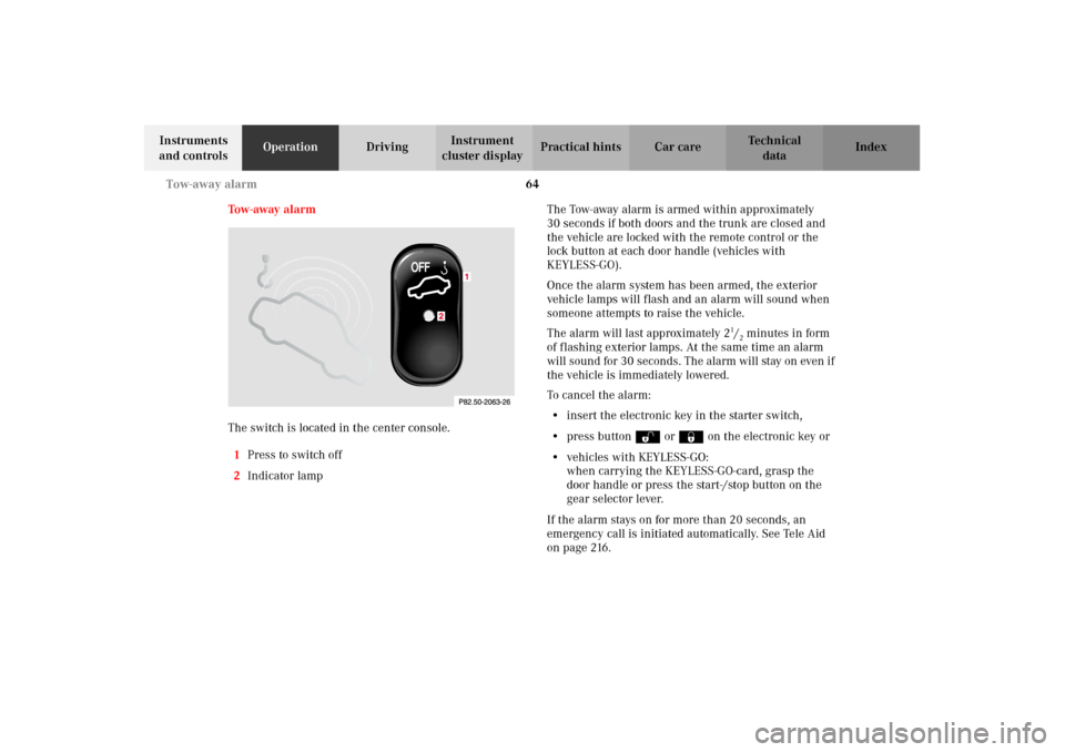
The switch is located in the center console.
1Press to switch off
2Indicator lampThe Tow- away alarm i s armed wit hin ap proxim ately
30 seconds if both doors and the trunk are closed and
the vehicle are locked with the remote control or the
lock button at each door handle (vehicles with
KEYLESS-GO).
Once the alarm system has been armed, the exterior
vehicle lamps will flash and an alarm will sound when
someone attempts to raise the vehicle.
The alarm will last approximately 2
1/2minutes in form
of flashing exterior lamps. At the same time an alarm
will sound for 30 seconds. The alarm will stay on even if
the vehicle is immediately lowered.
To cancel the alarm:
•insert the electronic key in the starter switch,
•press buttonŒ or‹ on the electronic key or
•vehicles with KEYLESS-GO:
when carrying the KEYLESS-GO-card, grasp the
door handle or press the start-/stop button on the
gear selector lever.
If the alarm stays on for more than 20 seconds, an
emergency call is initiated automatically. See Tele Aid
on page 216.
J_OM_215.book Seite 64 Mittwoch, 30. Mai 2001 2:01 14
Page 212 of 430

209 Garage door opener
Te ch n i c a l
data Instruments
and controlsOperationDrivingInstrument
cluster displayPractical hints Car care Index For operation in the USA only: This device complies
with Part 15 of the FCC Rules. Operation is subject to
the following two conditions:
(1) This device may not cause harmful interference, and
(2) this device must accept any interference received,
including interference that may cause undesired
operation.
Any unauthorized modification to this device could void
to the user’s authority to operate the equipment.
Programming or reprogramming the integrated
remote control:
1. Turn electronic key in starter switch to position 1
or 2.
2. Hold the end of the hand-held transmitter of the
device you wish to train approximately 2 to 5 inches
(5 cm to 12 cm) away from the surface of the
integrated remote control located on the inside rear
view mirror, keeping the indicator lamp in view.3. Using both hands, simultaneously push the hand-
held transmitter button and the desired integrated
remote control button. Do not release the buttons
until completing step 4.
4. The indicator lamp on the integrated remote control
will flash, first slowly and then rapidly. When the
indicator lamp flashes rapidly, both buttons may be
released (the rapid flashing lamp indicates
successful programming of the new frequency
signal). To program the remaining two buttons,
follow steps 1 through 4.
Note:
If, after repeated attempts, you do not successfully
program the integrated remote control device to learn
the signal of the hand-held transmitter, the garage door
opener could be equipped with the “rolling code
feature”.
J_OM_215.book Seite 209 Mittwoch, 30. Mai 2001 2:01 14
Page 214 of 430
211 Garage door opener
Te ch n i c a l
data Instruments
and controlsOperationDrivingInstrument
cluster displayPractical hints Car care Index Operation of remote control:
1. Turn electronic key in starter switch to position 1
or 2.
2. Select and press the appropriate button to activate
the remote controlled device. The integrated remote
control transmitter continues to send the signal as
long as the button is pressed – up to 20 seconds.Erasing the remote control memory:
1. Turn electronic key in starter switch to position 1
or 2.
2. Simultaneously holding down the left and right side
buttons for approximately 20 seconds, or until the
control lamp blinks rapidly, will erase the codes of
all three channels.
J_OM_215.book Seite 211 Mittwoch, 30. Mai 2001 2:01 14
Page 219 of 430
216 Tele Aid
Te ch n i c a l
data Instruments
and controlsOperationDrivingInstrument
cluster displayPractical hints Car care Index
Tele Aid
Important!
The initial activation of the Tele Aid system may only be
performed by completing the subscriber agreement and
placing an acquaintance call using the “SOS” button.
Failure to complete either of these steps will result in a
system that is not activated. If the system is not
activated the indicator lamp in the “SOS” button stays
on after turning electronic key in starter switch to
position 2 (vehicles with KEYLESS-GO:
operating position, see page 230) and the message
“TELE AID – NOT ACTIVATED” will be shown in the
multifunction display for approx. 10 seconds.
If you have any questions regarding activation, please
call the Response Center at 1-800-756-9018 (in the USA)
or 1-888-923-8367 (in Canada).
(Te l ematic Alarm Identification on Demand)
The Tele Aid system consists of three types of response;
automatic and manual emergency, roadside assistance
and information.
The Tele Aid system is operational providing that the
vehicle’s battery is charged, properly connected, not
damaged and cellular and GPS coverage is available.The speaker volume of a Tele Aid call can be adjusted
when using the volume control on the multifunction
steering wheel, for raising press buttonæ and for
lowering press buttonç.
To activate, press the “SOS” button, the Roadside
Assistance button or the Information button¡,
depending on the type of response required.
Shortly after the completion of your Acquaintance Call,
you will receive a user ID and password via first call
mail. By visiting www.mbusa.com and selecting
“Tele Aid” (USA only), you will have access to account
information, remote door unlock, Info Services* profile
and more.
* Optional System self-check
Initially, after turning the electronic key in starter
switch to position 2, malfunctions are detected and
indicated (the indicator lamps in the “SOS” button, the
Roadside Assistance button and the Information
button¡ stay on longer than 10 seconds or do not
come on). The message “TELE AID – VISIT
WORKSHOP” appears for approx. 10 seconds in the
multifunction display.
J_OM_215.book Seite 216 Mittwoch, 30. Mai 2001 2:01 14
Page 223 of 430

220 Tele Aid
Te ch n i c a l
data Instruments
and controlsOperationDrivingInstrument
cluster displayPractical hints Car care Index
Roadside Assistance button
Located below the center armrest cover is the Roadside
Assistance button. Pressing and holding the
button (for longer than 2 seconds) will initiate a call to a
Mercedes-Benz Roadside Assistance dispatcher. The
button will flash while the call is in progress. The
message “ROADSIDE ASSISTANCE – CONNECTING
CALL” will appear in the multifunction display. When
the connection is established, the message “ROADSIDE
ASSISTANCE – CALL CONNECTED” appears in the
multifunction display. The Tele Aid system will transmit
data generating the vehicle identification number,
model, color and location (subject to availability of
cellular and GPS signals).A voice connection between the Roadside Assistance
dispatcher and the occupants of the vehicle will be
established. When a voice connection is established the
audio system mutes and the message “TELE AID -
ROADSIDE ASSISTANCE CALL ACTIVE” appears in the
multifunction display. The nature of the need for
assistance can then be described. The Mercedes-Benz
Roadside assistance dispatcher will either dispatch a
qualified Mercedes-Benz technician or arrange to tow
your vehicle to the nearest Mercedes-Benz Center. For
ser vic es s uch as labor an d / or towi ng charges m ay ap ply.
Refer to the Roadside Assistance manual for more
information.
These programs are only available in the USA:
•S ign an d Drive s erv ices : Ser vi ces such as jump start,
a few gallons of fuel or the replacement of a flat tire
with the vehicle spare tire are obtainable,
•Remote Vehicle Diagnostics: This function permits
the Mercedes-Benz Roadside Assistance dispatcher
to download malfunction codes and actual vehicle
data.
Wa r n i n g !
If you feel at any way in jeopardy when in the
vehicle (e.g. smoke or fire in the vehicle, vehicle in
a dangerous road location), please do not wait for
voice contact after you have pressed the emergency
button. Carefully leave the vehicle and move to a
safe location. The Response Center will
automatically contact local emergency officials
with the vehicle’s approximate location if they
rec eive a n a utom at ic “SO S” si gna l a nd ca nn ot ma ke
voice contact with the vehicle occupants.
J_OM_215.book Seite 220 Mittwoch, 30. Mai 2001 2:01 14
Page 332 of 430
329 Contents - Practical hints
Te ch n i c a l
data Instruments
and controlsOperation DrivingInstrument
cluster displayPractical hintsCar care Index
Practical hintsFirst aid kit .....................................330
Fuses ................................................ 331
Shelf below rear window ..............333
Hood .................................................334
Checking engine oil level .............337
Automatic transmission
fluid level ...................................338
Active body control
(ABC) fluid level ........................338
Coolant level ...................................339
Adding coolant ...........................339
Windshield and headlamp
washer system ...........................340
Windshield and headlamp
washer fluid mixing ratio .........340Spare wheel, vehicle tools, storage
compartment ............................. 341
Jack .................................................. 342
Wheels ............................................ 343
Tire Replacement ....................... 343
Rotating wheels ......................... 344
Spare wheel .................................... 344
Changing wheels ........................... 346
Tire inflation pressure ................. 351
Battery ............................................. 352
Jump starting ................................. 355
Towing the vehicle ........................ 357
Exterior lamps ............................... 360
Headlamp assembly .................. 361
Taillamp assemblies .................. 364
Standby bulb function .................. 367Changing batteries
in the electronic key .................369
Synchronizing
remote control ............................ 371
Changing batteries in
the KEYLESS-GO-card ..............372
Emergency engine shut-down ..... 374
Fuel filler flap,
manual release .......................... 374
Emergency operation of
sliding/pop-up roof ...................375
Replacing wiper blades ................. 376
Roof rack .........................................378
J_OM_215.book Seite 329 Mittwoch, 30. Mai 2001 2:01 14
Page 374 of 430
371 Electronic key
Te ch n i c a l
data Instruments
and controlsOperation DrivingInstrument
cluster displayPractical hintsCar care Index Important!
Batteries contain materials that can harm the
environment if disposed of improperly. Recycling of
batteries is the preferred method of disposal. For
disposal, please follow manufacturer’s recommendation
on battery package.
Replacement Battery:
Lithium, type CR 2025 or equivalent.Synchronizing remote control
The remote control may have to be resynchronized, if
the vehicle cannot be locked or unlocked.
To synchronize insert electronic key in starter switch.
The remote control should once again be operational.
J_OM_215.book Seite 371 Mittwoch, 30. Mai 2001 2:01 14
Page 413 of 430

410 Index
Te ch n i c a l
data Instruments
and controlsOperation DrivingInstrument
cluster displayPractical hints Car careIndex
DDashboard ......................................................................... 22
Deep water
Driving instructions ................................................. 254
DISPLAY DEFECTIVE (engine control unit) -
malfunction and warning messages ......................304
DISPLAY DEFECTIVE (several systems) -
malfunction and warning messages ......................304
Display illumination .......................................................116
Distronic (DTR) ...................................................... 135, 259
Activation of Distronic ............................................. 262
Additional driving hints .......................................... 267
Cleaning sensor ........................................................ 384
Deactivation of Distronic .........................................264
Displays in the speedometer dial ........................... 274
Distance warning function ...................................... 270
Distronic settings ...................................................... 271
Driving with Distronic activated ............................265
Invalid attempts to activate ..................................... 263
Multifunction display ...............................................273
Warning lamp ............................................................ 301
DISTRONIC (DTR) -
malfunction and warning messages ......................327
DOOR -
malfunction and warning messages ......................322Door control panel ........................................................... 20
Door entry lamps ........................................................... 190
Doors ..................................................................................47
Power closing assist .................................................... 49
Drinking and driving .................................................... 245
Drive sensibly - save fuel ............................................. 245
Driving instructions ..................................................... 245
Driving off ...................................................................... 247
EEasy-entry/exit feature ...................................................66
ELEC. STABIL. PROGR. -
malfunction and warning messages ..................... 309
Electronic key ................................................................... 29
Changing batteries .................................................. 369
Starting the engine .................................................. 233
Turning off the engine ............................................ 233
Electronic main key
Synchronizing remote control ................................ 371
Electronic stability program (ESP) ............................. 278
Warning lamp ............................................................301
Emergency call
See Tele Aid ............................................................... 216
Emergency engine shut-down ...................................... 374
J_OM_215.book Seite 410 Mittwoch, 30. Mai 2001 2:01 14
Page 421 of 430
418 Index
Te ch n i c a l
data Instruments
and controlsOperation DrivingInstrument
cluster displayPractical hints Car careIndex
Service indicator
See Flexible service system (FSS) .......................... 150
Setting the audio volume .............................................. 149
Shelf below rear window ..............................................333
Side impact airbags ......................................................... 95
Side marker lamp ..........................................................366
Simultaneous use of
electronic main key and
KEYLESS-GO-card ....................................................... 43
Sliding/pop-up roof ....................................................... 186
Emergency operation ...............................................375
Opening and closing .................................................. 44
Synchronizing ........................................................... 188
Snow chains .................................................................... 251
SOS-call
See Tele Aid ............................................................... 216
Spare wheel .................................................................... 344
Spare wheel, vehicle tools,
storage compartment ................................................ 341
Special settings
(Automatic climate control) .................................... 174
SRS indicator lamp ........................................................ 299
SRS malfunction .............................................................. 92
Standby bulb function ................................................... 367Start lock-out ..................................................................... 31
Electronic main key .................................................... 31
KEYLESS-GO-card ....................................................... 31
Starter switch .........................................................228, 230
Starting and turning off the engine ........................... 233
Starting the engine
Electronic key ........................................................... 233
KEYLESS-GO ............................................................. 234
Steering lock
See Starter switch ............................................228, 230
Steering wheel
Easy-entry/exit feature .............................................. 66
Storage compartment
Trunk floor ................................................................. 341
Storage compartment in the
rear passenger compartment .................................. 198
Storage compartments and armrests .......................... 193
Center console ........................................................... 195
Glove box .................................................................... 194
Storing mirror positions ............................................... 107
Sun visors ........................................................................ 192
Supplemental restraint system (SRS) ........................... 90
Synchronizing remote control ..................................... 371
J_OM_215.book Seite 418 Mittwoch, 30. Mai 2001 2:01 14