weight MERCEDES-BENZ CLA 2016 Owners Manual
[x] Cancel search | Manufacturer: MERCEDES-BENZ, Model Year: 2016, Model line: CLA, Model: MERCEDES-BENZ CLA 2016Pages: 374, PDF Size: 9.97 MB
Page 20 of 374
Warning lamp ................................. 270
Warning message .......................... 338
TIREFIT kit .......................................... 312
Tire pressure not reached .............. 314
Tire pressure reached .................... 314
Tires
Aspect ratio (definition) ................. 350
Average weight of the vehicle
occupants (definition) .................... 349
Bar (definition) .............................. .3 48
Changing a wheel .......................... 351
Characteristics .............................. 348
Checking ........................................ 329
Curb weight (definition) ................. 350
Definition of terms ......................... 348
Direction of rotation ...................... 351
Display message ............................ 250
Distribution of the vehicle occu-
pants (definition) ............................ 351
DOT (Department of Transporta-
tion) (definition) ............................. 349
DOT, Tire Identification Number
(TIN) ............................................... 348
GAWR (Gross Axle Weight Rating)
(definition) ..................................... 349
General notes ................................ 355
GVW (Gross Vehicle Weight) (def-
inition) ........................................... 349
GVWR (Gross Vehicle Weight Rat-
ing) (definition) .............................. 349
Important safety notes .................. 328
Increased vehicle weight due to
optional equipment (definition) ...... 349
Information on driving .................... 328
Kilopascal (kPa) (definition) ........... 349
Labeling (overview) ........................ 345
Load bearing index (definition) ...... 350
Load index ..................................... 347
Load index (definition) ................... 349
M+S tires ....................................... 330
Maximum load on a tire (defini-
tion) ............................................... 350
Maximum loaded vehicle weig ht
( d
efinition) ..................................... 349
Maximum permissible tire pres-
sure (definition) ............................. 350
Maximum tire load ......................... 347
Maximum tire load (definition) ....... 350 MOExtended tires .......................... 330
Optional equipment weight (defi-
nition) ............................................ 350
PSI (pounds per square inch) (def-
inition) ........................................... 350
Replacing ....................................... 351
Service life ..................................... 330
Sidewall (definition) ....................... 350
Speed rating (definition) ................ 349
Storing ........................................... 351
Structure and characteristics
(definition) ..................................... 348
Summer tires ................................. 330
Temperature .................................. 344
TIN (Tire Identification Number)
(definition) ..................................... 350
Tire bead (definition) ...................... 350
Tire pressure (definition) ................ 350
Tire pressures (recommended) ...... 349
Tire size (data) ............................... 355
Tire size designation, load-bearing
capacity, speed rating .................... 345
Tire tread ....................................... 329
Tire tread (definition) ..................... 350
Total load limit (definition) ............. 351
Traction ......................................... 344
Traction (definition) ....................... 350
Tread wear ..................................... 344
Uniform Tire Quality Grading
Standards ...................................... 343
Uniform Tire Quality Grading
Standards (definition) .................... 349
Wear indicator (definition) ............. 350
Wheel and tire combination ........... 357
Wheel rim (definition) .................... 349
see Flat tire
Top Tether ............................................ 61
Tow-starting
Emergency engine starting ............ 325
Important safety notes .................. 321
Installing the towing eye ................ 322
Removing the towing eye ............... 323
Towing a trailer
ESP ®
(Electronic Stability Pro-
gram) ............................................... 72
To w ing away
Important safety guidelines ........... 321
Installing the towing eye ................ 32218
Index
Page 23 of 374
Protection of the environment
General notes
H Environmental note
Daimler's declared policy is one of compre-
hensive environmental protection.
The objectives are for the natural resources
that form the basis of our existence on this
planet to be used sparingly and in a manner
that takes the requirements of both nature
and humanity into account.
You too can help to protect the environment
by operating your vehicle in an environmen-
tally responsible manner.
Fuel consumption and the rate of engine,
transmission, brake and tire wear are affected
by these factors: R
operating conditions of your vehicle R
your personal driving style
You can influence both factors. You should
bear the following in mind:
Operating conditions: R
avoid short trips as these increase fuel con-
sumption. R
always make sure that the tire pressures
are correct. R
do not carry any unnecessary weight. R
remove roof racks once you no longer need
them. R
a regularly serviced vehicle will contribute
to environmental protection. You should
therefore adhere to the service intervals. R
always have service work carried out at a
qualified specialist workshop.
Personal driving style: R
do not depress the accelerator pedal when
starting the engine. R
do not warm up the engine when the vehicle
is stationary. R
drive carefully and maintain a safe distance
from the vehicle in front. R
avoid frequent, sudden acceleration and
braking. R
change gear in good time and use each gear
only up to �
Page 47 of 374
tion. This poses an increased risk of injury or
even fatal injury.
Make sure that all vehicle occupants are
seated properly with a correctly fastened seat
belt.
G WARNING
The seat belt does not offer the intended level
of protection if you have not moved the back-
rest to an almost vertical position. When brak-
ing or in the event of an accident, you could
slide underneath the seat belt and sustain
abdomen or neck injuries, for example. This
poses an increased risk of injury or even fatal
injury.
Adjust the seat properly before beginning
your journey. Always ensure that the backrest
is in an almost vertical position and that the
shoulder section of your seat belt is routed
across the center of your shoulder.
G WARNING
Persons under 5 ft (1.50 m) in height cannot
fasten the seat belt correctly without an addi-
tional suitable restraint system. If the seat
belt is incorrectly fastened, it cannot protect
as intended. Furthermore, an incorrectly fas-
tened seat belt can cause additional injury, for
example, in an accident, during braking or an
abrupt change of direction. This poses an
increased risk of injury or even fatal injury.
For this reason, always secure persons under
5 ft (1.50 m) in height in suitable restrain t
systems.
If a child younger than twelve years old and
under 5 ft (1.50 m) in height is traveling in the
vehicle: R
always secure the child in a child restraint
system suitable for this Mercedes-Benz
vehicle. The child restraint system must be
appropriate to the age, weight and size of
the child R
always observe the instructions and safety
notes in the "Children in the vehicle" sec-
tion of this Operator's Manual ( Y
page 58) in addition to the child
restraint system manufacturer's installa-
tion instructions R
be sure to observe the instructions and
safety notes on the "Occupant classifica-
tion system (OCS)" ( Y
page 51)
G WARNING
The seat belts may not perform their intended
protective function if: R
they are damaged, modified, extremely
dirty, bleach or dyed R
the seat belt buckle is damaged or
extremely dirty R
the Emergency Tensioning Devices, belt
anchorages or inertia reels have been modi-
fied
Seat belts may sustain non-visible damage in
an accident, e.g. due to glass splinters. Modi-
fied or damaged seat belts may tear or fail,
e.g. in an accident. Modified Emergency Ten-
sioning Devices could accidentally trigger or
fail to deploy when necessary. This poses an
increased risk of injury or even fatal injury.
Never modify the seat belts, Emergency Ten-
sioning Devices, belt anchorages or inertia
reels. Make sure that the seat belts are
undamaged, not worn out and clean. Follow-
ing an accident, have the seat belts checked
immediately at a qualified specialist work-
shop.
Only use seat belts that have been approved
for your vehicle by Mercedes-Benz.
Sports seat or AMG Performance seat: this
seat is designed for the standard three-point
seat belt. If you install another mu lti-point
s eat belt, e.g. sport or racing seat belts, the
restraint system cannot provide the best level
of protection.
G WARNING
If you feed seat belts through the opening in
the seat backrest, the seat backrest may be
damaged or may even break in the event of an
accident. This poses an increased risk of
injury or even fatal injury.Occupant safety 45
Safety Z
Page 51 of 374
R
Only secure a child in a rearward-facing
child restraint system on the front-
passenger seat when the front-passenger
front air bag is deactivated. If the
PASSENGER AIR BAG OFF indicator lamp is
permanently lit, the front-passenger front
air bag is deactivated ( Y
page 43).R
Always observe the instructions and safety
notes on the "Occupant Classification Sys-
tem (OCS)" ( Y
page 51) and on "Children
in the vehicle" ( Y
page 58) in addition to
the child restraint system manufacturer's
installation instructions.
Objects in the vehicle interior may pre-
vent an air bag from functioning correctly.
Before starting your journey and to avoid risks
resulting from the speed of the air bag as it
deploys, make sure that: R
there are no people, animals or objects
between the vehicle occupants and an air
bag. R
there are no objects between the seat, door
and B-pillar. R
no hard objects, e.g. coat hangers, hang on
the grab handles or coat hooks. R
no accessories, such as cup holders, are
attached to the vehicle within the deploy-
ment area of an air bag, e.g. to doors, side
windows, rear side trim or side walls. R
no heavy, sharp-edged or fragile objects
are in the pockets of your clothing. Store
such objects in a suitable place.
G WARNING
If you modify the air bag cover or affix objects
such as stickers to it, the air bag can no longer
function correctly. There is an increased risk
of injury.
Never modify an air bag cover or affix objects
to it.
G WARNING
Sensors to control the air bags are located in
the doors. Modifications or work not per-
formed correctly to the doors or door panel-
ing, as well as damaged doors, can lead to the function of the sensors being impaired. The air
bags might therefore not function properly
anymore. Consequently, the air bags cannot
protect vehicle occupants as they are
designed to do. There is an increased risk of
injury.
Never modify the doors or parts of the doors.
Always have work on the doors or door pan-
eling carried out at a qualified specialist work-
shop.
Front air bags
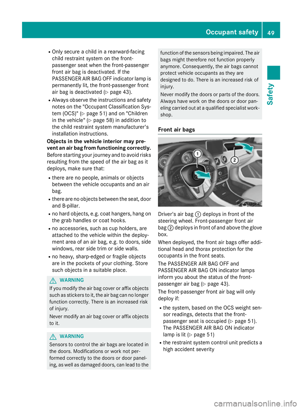
Driver's air bag �C deploys in front of the
steering wheel. Front-passenger front air
bag �D deploys in front of and above the glove
box.
When deployed, the front air bags offer addi-
tional head and thorax protection for the
occupants in the front seats.
The PASSENGER AIR BAG OFF and
PASSENGER AIR BAG ON indicator lamps
inform you about the status of the front-
passenger air bag ( Y
page 43).
The front-passenger front air bag will only
deploy if: R
the system, based on the OCS weight sen-
sor readings, detects that the front-
passenger seat is occupied ( Y
page 51).
The PASSENGER AIR BAG ON indicator
lamp is lit ( Y
page 51) R
the restraint system control unit predicts a
high accident severityOccupant safety 49
Safety Z
Page 53 of 374
However, it does not protect the chest or
arms.
In the event of a side impact, the window cur-
tain air bag is deployed on the side on which
the impact occurs.
If the system determines that they can offer
additional protection to that provided by the
seat belt, a window curtain air bag may be
deployed in other accident situations
( Y
page 56).
Occupant Classification System
(OCS)
Introduction The Occupant Classification System (OCS)
categorizes the person in the front-passenger
seat. Depending on that result, the front-
passenger front air bag and front-passenger
knee bag are either enabled or deactivated.
The system does not disable: R
the side impact air bag R
the window curtain air bag R
the Emergency Tensioning Devices
Prerequisites
To be classified correctly, the front passenger
must sit: R
with the seat belt fastened correctly R
in an almost upright position with their
back against the seat backrest R
with their feet resting on the floor, if possi-
ble
If the front passenger does not observe these
conditions, OCS may produce a false classi-
fication, e.g. because the front passenger: R
transfers their weight by supporting them-
selves on a vehicle armrest R
sits in such a way that their weight is raised
from the seat cushion
If it is absolutely necessary to install a child
restraint system on the front-passenger seat,
be sure to observe the correct positioning of the child restraint system. Never place
objects under or behind the child restraint
system, e.g. cushions. The entire base of the
child restraint system must always rest on the
seat cushion of the front-passenger seat. The
backrest of the forward-facing child restraint
system must lie as flat as possible against the
backrest of the front-passenger seat.
The child restraint system must not touch the
roof or be subjected to a load by the head
restraint. Adjust the angle of the seat back-
rest and the head restraint position accord-
ingly.
Only then can OCS be guaranteed to function
correctly. Always observe the child restraint
system manufacturer's installation instruc-
tions.
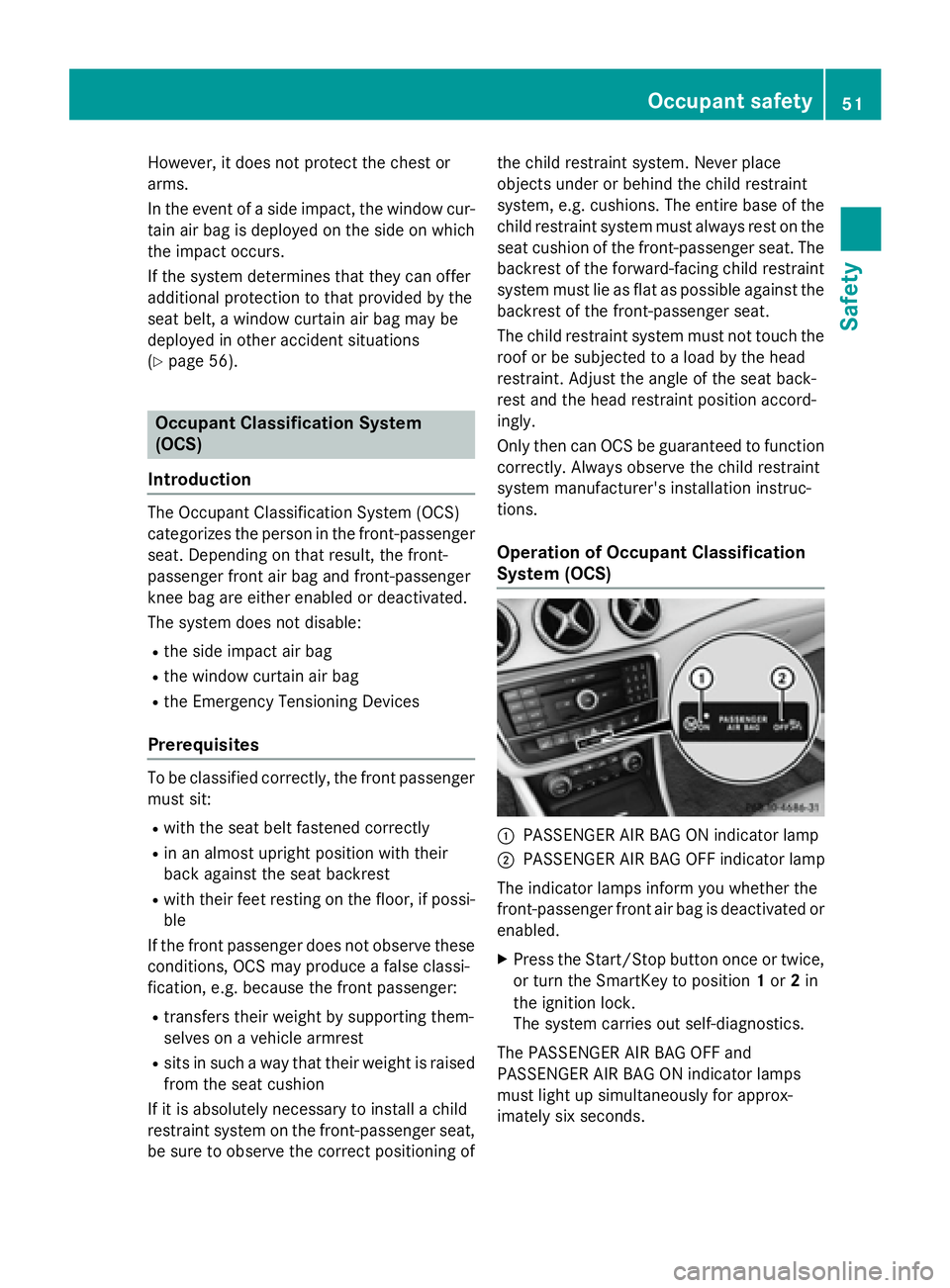
Operation of Occupant Classification
System (OCS)
�C
PASSENGER AIR BAG ON indicator lamp �D
PASSENGER AIR BAG OFF indicator lamp
The indicator lamps inform you whether the
front-passenger front air bag is deactivated or
enabled. X
Press the Start/Stop button once or twice,
or turn the SmartKey to position 1 or 2 in
the ignition lock.
The system carries out self-diagnostics.
The PASSENGER AIR BAG OFF and
PASSENGER AIR BAG ON indicator lamps
must light up simultaneously for approx-
imately six second s.Occu pant safety 51
Safety Z
Page 57 of 374
Problems with the Occupant Classification System (OCS) Be sure to observe the notes on "System self-test" ( Y
page 53).
Problem
Possible causes/consequences and �P Solutions
The PASSENGER AIR
BAG OFF indicator
lamp lights up and
remains lit, even
though the front-
passenger seat is occu-
pied by an adult or a
person of a stature cor-
responding to that of an
adult. The classification of the person on the front-passenger seat is
incorrect. X
Make sure the conditions for a correct classification of the per-
son on the front-passenger seat are met ( Y
page 51).X
If the PASSENGER AIR BAG OFF indicator lamp remains lit, the
front-passenger seat may not be used. X
Have OCS checked as soon as possible at an authorized
Mercedes-Benz Center.
The PASSENGER AIR
BAG OFF indicator
lamp does not light up
and/or does not stay
on.
The front-passenger
seat is: R
unoccupied R
occupied with the
weight of a child up
to twelve months old
in a child restraint
system OCS is malfunctioning. X
Make sure there is nothing between the seat cushion and the
child seat. X
Make sure that the entire base of the child restraint system rests
on the seat cushion of the front-passenger seat. The backrest of
the forward-facing child restraint system must lie as flat as pos-
sible against the backrest of the front-passenger seat. If nec-
essary, adjust the position of the front-passenger seat. X
Make sure that the seat cushion length is fully retracted. X
When installing the child restraint system, make sure that the
seat belt is tight. Do not pull the seat belt tight using the front-
passenger seat adjustment. This could result in the seat belt and
the child restraint system being pulled too tightly. X
Check for correct installation of the child restraint system.
Make sure that the head restraint does not apply a load to the
child restraint system. If necessary, adjust the head restraint
accordingly. X
Make sure that no objects are applying additional weight onto
the seat. X
If the PASSENGER AIR BAG OFF indicator lamp remains off and/
or the PASSENGER AIR BAG ON indicator lamp lights up, do not
install a child restraint system on the front-passenger seat. It is
recommended that you install the child restraint system on a
suitable rear seat. X
Have OCS checked as soon as possible at an authorized
Mercedes-Benz Center. Occupant safety 55
Safety Z
Page 60 of 374
How the air bag system works is deter-
mined by the severity of the accident detec-
ted, especially the vehicle deceleration or
acceleration and the apparent type of acci-
dent: R
frontal collision R
side impact R
rollover
Automatic measures after an acci-
dentImmediately after an accident, the following
measures are implemented, depending on
the type and severity of the impact: R
the hazard warning lamps are activated R
the emergency lighting is activated R
the vehicle doors are unlocked R
the front side windows are lowered R
the engine is switched off and the fuel sup-
ply is cut off R
vehicles with mbrace: automatic emer-
gency call
Children in the vehicle
Important safety notes
Accident statistics show that children
secured in the rear seats are safer than chil-
dren secured in the front-passenger seat. For
this reason, Mercedes-Benz strongly advises
that you install a child restraint system on a
rear seat. Children are generally better pro-
tected there.
If a child younger than twelve years old and
under 5 ft (1.50 m) in height is traveling in the
vehicle: R
always secure the child in a child restraint
system suitable for Mercedes-Benz vehi-
cles. The child restraint system must be appropriate to the age, weight and size of
the child R
be sure to observe the instructions and
safety notes in this section in addition to
the child restraint system manufacturer's
installation instructions R
be sure to observe the instructions and
safety notes on the "Occupant Classifica-
tion System (OCS)" ( Y
page 51)
G WARNING
If you leave children unsupervised in the vehi-
cle, they could set it in motion by, for example: R
release the parking brake. R
shift the automatic transmission out of the
parking position P .R
start the engine.
In addition, they may operate vehicle equip-
ment and become trapped. There is a risk of
an accident and injury.
When leaving the vehicle, always take the
SmartKey with you and lock the vehicle. Never
leave children unsupervised in the vehicle.
G WARNING
If persons, particularly children are subjected
to prolonged exposure to extreme heat or
cold, there is a risk of injury, possibly even
fatal. Never leave children unattended in the
vehicle.
G WARNING
If the child restraint system is subjected to
direct sunlight, parts may get very hot. Chil-
dren may burn themselves on these parts,
particularly on the metal parts of the child
restraint system. There is a risk of injury.
If you leave the vehicle, taking the child with
you, always ensure that the child restraint
system is not exposed to direct sunlight. Pro-
tect it with a blanket, for example. If the child
restraint system has been exposed to direct
sunlight, let it cool down before securing the
child in it. Never leave children unattended in
the vehicle.58
Children in the vehicle
Safety
Page 62 of 374
tions and the notes on use. Please ensure,
that the base of the child restraint system is
always resting completely on the seat cush-
ion. Never place objects, e.g. cushions, under
or behind the child restraint system. Only use
child restraint systems with the original cover
designed for them. Only replace damaged
covers with genuine covers.
G WARNING
If the child restraint system is installed incor-
rectly or is not secured, it can come loose in
the event of an accident, heavy braking or a
sudden change in direction. The child
restraint system could be thrown about, strik-
ing vehicle occupants. There is an increased
risk of injury, possibly even fatal.
Always install child restraint systems prop-
erly, even if they are not being used. Make
sure that you observe the child restraint sys-
tem manufacturer's installation instructions.
You will find further information on stowing
objects, luggage or loads under "Loading
guidelines" ( Y
page 272).
G WARNING
Child restraint systems or their securing sys-
tems which have been damaged or subjected
to a load in an accident can no longer protect
as intended. The child cannot then be
restrained in the event of an accident, heavy
braking or sudden changes of direction. There
is an increased risk of injury, possibly even
fatal.
Replace child restraint systems which have
been damaged or subjected to a load in an
accident as soon as possible. Have the secur-
ing systems on the child restraint system
checked at a qualified specialist workshop,
before you install a child restraint system
again. The securing systems of child restraint sys-
tems are: R
the seat belt system R
the LATCH-type (ISOFIX) securing rings R
the Top Tether anchorages
If it is absolutely necessary to carry a child on
the front-passenger seat, be sure to observe
the information on the "Occupant Classifica-
tion System (OCS)" ( Y
page 51). There you
will also find information on deactivating the
front-passenger front air bag.
All child restraint systems must meet the fol-
lowing standards: R
U.S. Federal Motor Vehicle Safety Stand-
ards 213 and 225 R
Canadian Motor Vehicle Safety Standards
213 and 210.2
Confirmation that the child restraint system
corresponds to the standards can be found
on an instruction label on the child restraint
system. This confirmation can also be found
in the installation instructions that are inclu-
ded with the child restraint system.
Observe the warning labels in the vehicle inte-
rior and on the child restraint system.
LATCH-type (ISOFIX) child seat secur-
ing system
G WARNING
LATCH-type (ISOFIX) child restraint systems
do not offer sufficient protective effect for
children whose weight is greater than 48 lbs
(22 kg) who are secured using the safety belt
integrated in the child restraint system. In the
event of an accident, a child might not be
restrained correctly. This poses an increased
risk of injury or even fatal injury.
If the child weighs more than 48 lbs (22 kg),
only use LATCH-type (ISOFIX) child restraint
systems with which the child is also secured
with the vehicle seat belt. Also secure the
child restraint system with the Top Tether
belt, if available.60
Children in the vehicle
Safety
Page 239 of 374
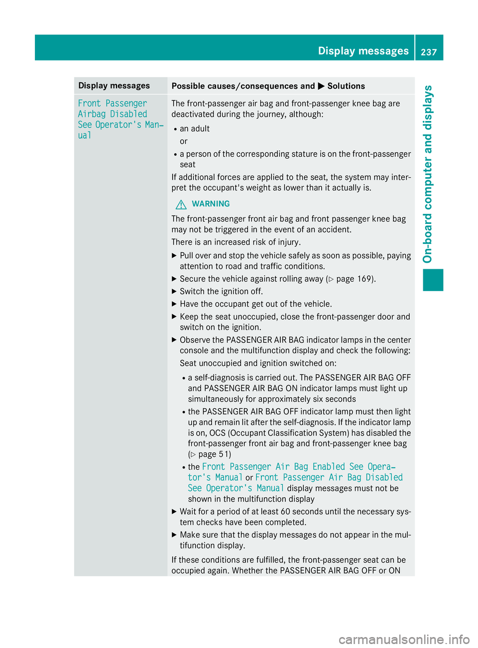
Display messages
Possible causes/consequences and �P Solutions
Front Passenger
Airbag Disabled
See Operator' s Man ‐
ual The front-passenger air bag and front-passenger knee bag are
deactivated during th e journey, although:R
an adult
or R
a person of th e correspondin g stature is on th e front-passenger
seat
If additional forces are applied to th e seat , th e system may inter-
pre t th e occupant's weight as lowe r than it actually is.
G WARNIN G
The front-passenger fron t air bag and fron t passenger knee bag
may no t be triggered in th e event of an accident.
There is an increase d ris k of injury.X
Pull ove r and stop th e vehicl e safely as soo n as possible, payin g
attention to roa d and traffic conditions.X
Secur e th e vehicl e against rollin g away ( Y
page 169).X
Switc h th e ignition off. X
Hav e th e occupant get out of th e vehicle.X
Kee p th e seat unoccupied , close th e front-passenger doo r and
switch on th e ignition .X
Observ e th e PASSENGER AI R BA G indicato r lamp s in th e center
console and th e multifunction display and chec k th e following :
Seat unoccupied and ignition switched on :R
a self-diagnosi s is carrie d out . The PASSENGER AI R BA G OF F
and PASSENGER AI R BA G ON indicato r lamp s mus t ligh t up
simultaneousl y fo r approximately six s econdsR
th e PASSENGER AI R BA G OF F indicato r lamp mus t then ligh t
up and remain lit after th e self-diagnosis. If th e indicato r lamp
is on , OCS (Occupant Classification System) has disabled th e
front-passenger fron t air bag and front-passenger knee bag
( Y
page 51) R
th e Front Passenger Air Bag Enable d See Opera‐
tor's Manual or Front Passenger Air Bag Disabled
See Operator' s Manual display message s mus t no t be
shown in th e multifunction displayX
Wait fo r a period of at leas t 60 seconds until th e necessar y sys-
te m checks hav e been completed.X
Mak e sur e that th e display message s do no t appea r in th e mul-
tifunction display.
If these condition s are fulfilled , th e front-passenger seat can be
occupied again . Whether th e PASSENGER AI R BA G OF F or ONDisplay messages 23 7
On-board computer and displays Z
Page 240 of 374
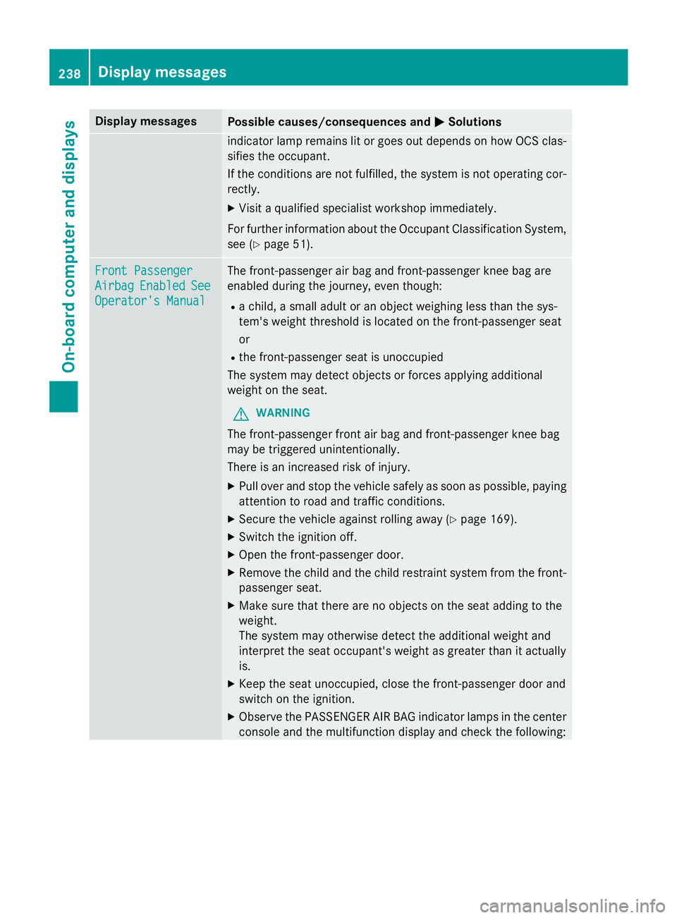
Display messages
Possible causes/consequences and �P Solutions
indicato r lamp remain s lit or goe s out depend s on how OCS clas-
sifies th e occupant .
If th e condition s are no t fulfilled , th e system is no t operating cor-
rectly. X
Visit a qualified specialist workshop immediately.
Fo r further information about th e Occupant Classification System,
see ( Y
page 51) .
Front Passenger
Airbag Enable d See
Operator' s Manual The front-passenger air bag and front-passenger knee bag are
enabled during th e journey, eve n though :R
a child, a small adult or an objec t weighin g less than th e sys-
tem' s weight threshold is locate d on th e front-passenger seat
or R
th e front-passenger seat is unoccupied
The system may detec t objects or forces applying additional
weight on th e seat .
G WARNIN G
The front-passenger fron t air bag and front-passenger knee bag
may be triggered unintentionally.
There is an increase d ris k of injury.X
Pull ove r and stop th e vehicl e safely as soo n as possible, payin g
attention to roa d and traffic conditions.X
Secur e th e vehicl e against rollin g away ( Y
page 169).X
Switc h th e ignition off. X
Ope n th e front-passenger door. X
Remove th e child and th e child restrain t system from th e front-
passenger seat .X
Mak e sur e that there are no objects on th e seat addin g to th e
weight .
The system may otherwise detec t th e additional weight and
interpret th e seat occupant's weight as greate r than it actually
is. X
Kee p th e seat unoccupied , close th e front-passenger doo r and
switch on th e ignition .X
Observ e th e PASSENGER AI R BA G indicato r lamp s in th e ce nter
console and th e multifunction display and chec k th e following :238
Display messages
On-board computer and displays