tow MERCEDES-BENZ CLA-Class 2014 C117 Workshop Manual
[x] Cancel search | Manufacturer: MERCEDES-BENZ, Model Year: 2014, Model line: CLA-Class, Model: MERCEDES-BENZ CLA-Class 2014 C117Pages: 358, PDF Size: 6.6 MB
Page 280 of 358
X
Turn the SmartKey to position 2in the igni-
tion lock (Y page 141).
X Press and hold buttons 0044and 0085.
The indicator lamp initially lights up yellow
and then green.
X Release buttons 0044and 0085.
The memory of the integrated garage door
opener in the rear-view mirror is cleared. Compass
Calling up the compass The compass displays in which compass
direction the vehicle is currently traveling:
N N,
NE
NE, E
E,SE
SE, S
S,SW
SW, W
Wor NW
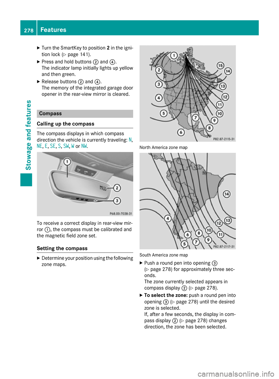
NW. To receive a correct display in rear-view mir-
ror 0043, the compass must be calibrated and
the magnetic field zone set.
Setting the compass X
Determine your position using the following
zone maps. North America zone map
South America zone map
X Push a round pen into opening 0087
(Y page 278) for approximately three sec-
onds.
The zone currently selected appears in
compass display 0044(Ypage 278).
X To select the zone: push a round pen into
opening 0087(Ypage 278) until the desired
zone is selected.
If, after a few seconds, the display in com-
pass display 0044(Ypage 278) changes
direction, the zone has been selected. 278
FeaturesStowage and features
Page 281 of 358
Calibrating the compass
X
Make sure that there is sufficient space for
you to drive in a circle without impeding
traffic.
In order to calibrate the compass correctly,
do the following:
R calibrate the compass in the open and not
in the vicinity of steel structures or high-
voltage transmission lines.
R switch off electrical consumers such as the
climate control, windshield wipers or rear
window defroster.
R close all doors and the trunk lid.
X Switch on the ignition.
X Push a round pen into opening 0087
(Y page 278) for approximately six sec-
onds, until symbol C
C is shown in compass
display 0044(Ypage 278).
X Drive your vehicle in a full circle at approx-
imately 3 mph (5 km/h) to 6 mph
(10 km/h).
When the calibration has successfully been completed, the current direction is shown
in compass display 0044(Ypage 278). Floormat on the driver's side
G
WARNING
Objects in the driver's footwell can restrict the pedal travel or obstruct a depressed pedal.
The operating and road safety of the vehicle is
jeopardized. There is a risk of an accident.
Make sure that all objects in the vehicle are
stowed correctly, and that they cannot enter
the driver's footwell. Install the floormats
securely and as specified in order to ensure
sufficient clearance for the pedals. Do not use loose floormats and do not place floormats on
top of one another. X
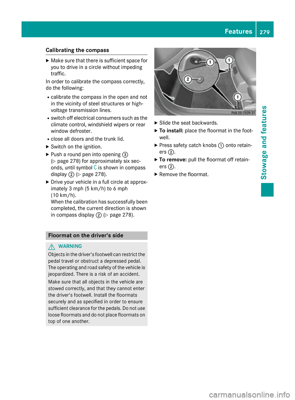
Slide the seat backwards.
X To install: place the floormat in the foot-
well.
X Press safety catch knobs 0043onto retain-
ers 0044.
X To remove: pull the floormat off retain-
ers 0044.
X Remove the floormat. Features
279Stowage and features Z
Page 290 of 358
should drive for a few minutes after clean-
ing. Braking heats the brake discs and the
brake pads/linings, thus drying them. The
vehicle can then be parked.
Regular care of your vehicle is a condition for
retaining the quality in the long term.
Use care products and cleaning agents rec-
ommended and approved by Mercedes-Benz. Exterior care
Automatic car wash G
WARNING
Braking efficiency is reduced after washing
the vehicle. There is a risk of an accident.
After the vehicle has been washed, brake
carefully while paying attention to the traffic
conditions until full braking power is restored.
! If DISTRONIC PLUS or the HOLD function
is activated, the vehicle brakes automati-
cally in certain situations. To prevent dam-
age to the vehicle, deactivate DISTRONIC
PLUS and the HOLD function in the follow-
ing or other similar situations:
R when towing the vehicle
R in the car wash
! Never clean your vehicle in a Touchless
Automatic Car Wash as these use special
cleaning agents. These cleaning agents can
damage the paintwork or plastic parts.
! Make sure that the automatic transmis-
sion is in position Nwhen washing your
vehicle in a tow-through car wash. The vehi-
cle could be damaged if the transmission is
in another position.
! Make sure that: R
the side windows and the sliding sunroof
are fully closed.
R the ventilation/heating is switched off
(the OFF button has been pressed/the
airflow control is set to position 0).
R the windshield wiper switch is in position
0.
Otherwise, the vehicle might be damaged.
You can wash the vehicle in an automatic car
wash from the very start.
If the vehicle is very dirty, pre-wash it before
cleaning it in an automatic car wash.
After using an automatic car wash, wipe off
wax from the windshield and the wiper
blades. This will prevent smears and reduce
wiping noises caused by residue on the wind- shield.
Washing by hand In some countries, washing by hand is only
allowed at wash bays that are specially
designed for this purpose. Observe the legal
requirements in all countries concerned.
X Do not use hot water and do not wash the
vehicle in direct sunlight.
X Use a soft sponge to clean.
X Use a mild cleaning agent, such as a car
shampoo approved by Mercedes-Benz.
X Thoroughly hose down the vehicle with a
gentle jet of water.
X Do not point the water jet directly towards
the air inlet.
X Use plenty of water and rinse out the
sponge frequently.
X Rinse the vehicle with clean water and dry
thoroughly with a chamois.
X Do not let the cleaning agent dry on the
paintwork.
When using the vehicle in winter, remove all
traces of road salt deposits carefully and as
soon as possible. 288
CareMaintenance and care
Page 297 of 358
Useful information
............................296
Where will I find...? ...........................296
Flat tire .............................................. 296
Battery (vehicle) ................................ 301
Jump-starting .................................... 305
Towing and tow-starting ..................307
Fuses .................................................. 310 295Breakdown assistance
Page 298 of 358
Useful information
i This Operator's manual describes all
models and all standard and optional equip- ment of your vehicle available at the time of
publication of the Operator's manual.
Country-specific differences are possible.
Please note that your vehicle may not be
equipped with all features described. This
also applies to safety-related systems and
functions.
i Read the information on qualified special-
ist workshops (Y page 26). Where will I find...?
Vehicle tool kit
General notes Vehicles with a TIREFIT kit: the TIREFIT kit is
located in the stowage well under the trunk
floor.
Vehicles with a tire-change tool kit: the tire-
change tool kit is in the stowage well under
the trunk floor.
i Apart from certain country-specific varia-
tions, the vehicles are not equipped with a
tire-change tool kit. Some tools for chang-
ing a wheel are specific to the vehicle. For
more information on which tire changing
tools are required and approved to perform
a wheel change on your vehicle, consult a
qualified specialist workshop.
Tools required for changing a wheel may
include, for example:
R Jack
R Wheel chock
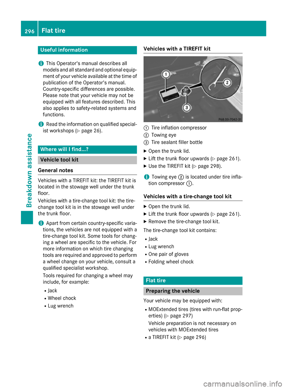
R Lug wrench Vehicles with a TIREFIT kit 0043
Tire inflation compressor
0044 Towing eye
0087 Tire sealant filler bottle
X Open the trunk lid.
X Lift the trunk floor upwards (Y page 261).
X Use the TIREFIT kit (Y page 298).
i Towing eye
0044is located under tire infla-
tion compressor 0043.
Vehicles with a tire-change tool kit X
Open the trunk lid.
X Lift the trunk floor upwards (Y page 261).
X Remove the tire-change tool kit.
The tire-change tool kit contains:
R Jack
R Lug wrench
R One pair of gloves
R Folding wheel chock Flat tire
Preparing the vehicle
Your vehicle may be equipped with:
R MOExtended tires (tires with run-flat prop-
erties) (Y page 297)
Vehicle preparation is not necessary on
vehicles with MOExtended tires
R a TIREFIT kit (Y page 296)296
Flat tireBreakdown assistance
Page 301 of 358
Using the TIREFIT kit
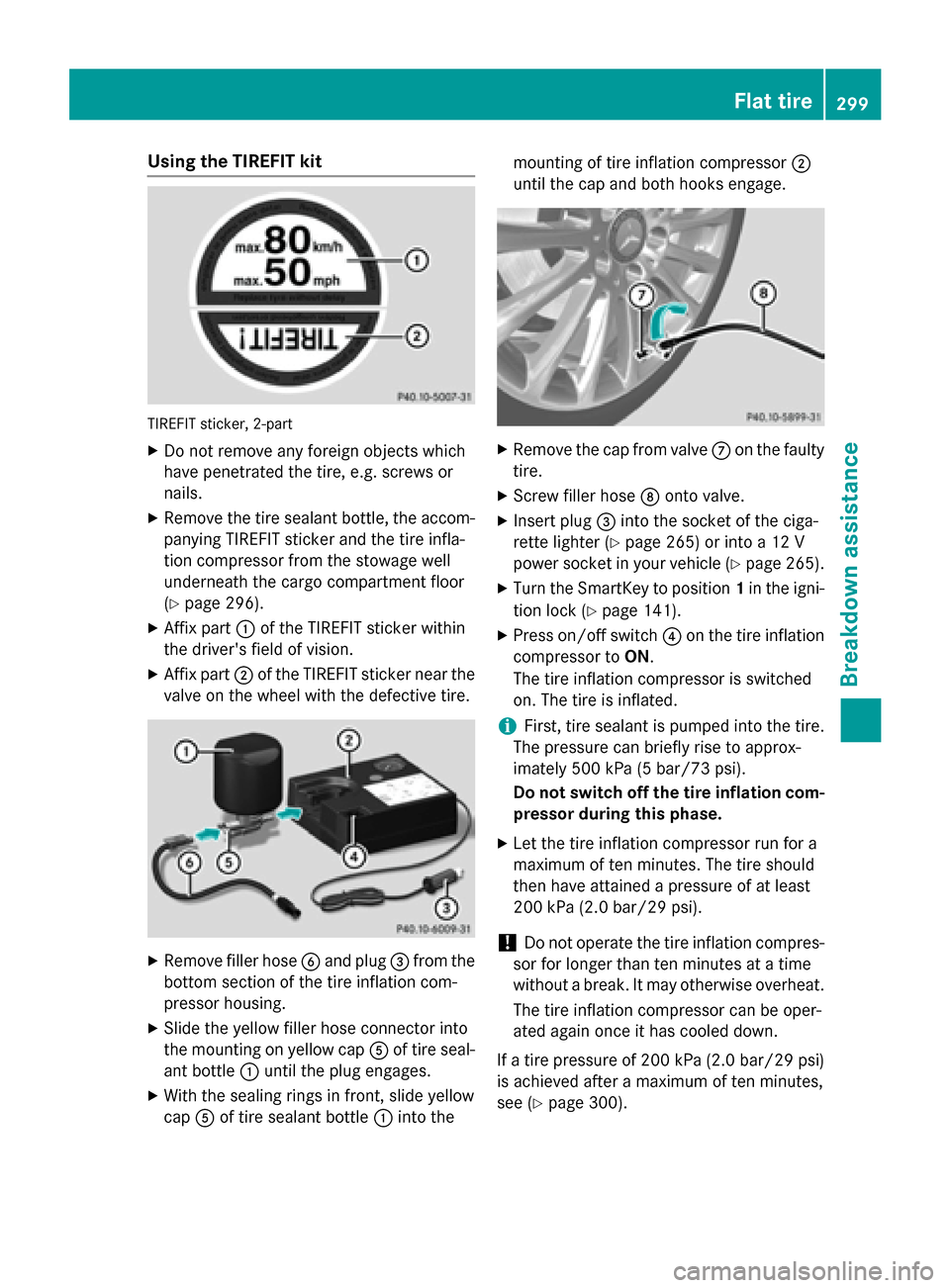
TIREFIT sticker, 2-part
X Do not remove any foreign objects which
have penetrated the tire, e.g. screws or
nails.
X Remove the tire sealant bottle, the accom-
panying TIREFIT sticker and the tire infla-
tion compressor from the stowage well
underneath the cargo compartment floor
(Y page 296).
X Affix part 0043of the TIREFIT sticker within
the driver's field of vision.
X Affix part 0044of the TIREFIT sticker near the
valve on the wheel with the defective tire. X
Remove filler hose 0084and plug 0087from the
bottom section of the tire inflation com-
pressor housing.
X Slide the yellow filler hose connector into
the mounting on yellow cap 0083of tire seal-
ant bottle 0043until the plug engages.
X With the sealing rings in front, slide yellow
cap 0083of tire sealant bottle 0043into the mounting of tire inflation compressor
0044
until the cap and both hooks engage. X
Remove the cap from valve 006Bon the faulty
tire.
X Screw filler hose 006Conto valve.
X Insert plug 0087into the socket of the ciga-
rette lighter (Y page 265) or into a 12 V
power socket in your vehicle (Y page 265).
X Turn the SmartKey to position 1in the igni-
tion lock (Y page 141).
X Press on/off switch 0085on the tire inflation
compressor to ON.
The tire inflation compressor is switched
on. The tire is inflated.
i First, tire sealant is pumped into the tire.
The pressure can briefly rise to approx-
imately 500 kPa (5 bar/73 psi).
Do not switch off the tire inflation com-
pressor during this phase.
X Let the tire inflation compressor run for a
maximum of ten minutes. The tire should
then have attained a pressure of at least
200 kPa (2.0 bar/29 psi).
! Do not operate the tire inflation compres-
sor for longer than ten minutes at a time
without a break. It may otherwise overheat.
The tire inflation compressor can be oper-
ated again once it has cooled down.
If a tire pressure of 200 kPa (2.0 bar/29 psi)
is achieved after a maximum of ten minutes,
see (Y page 300). Flat tire
299Breakdown assistance Z
Page 302 of 358
If a tire pressure of 200 kPa (2.0 bar/29 psi)
is not achieved after a maximum of ten
minutes, see (Y page 300).
i If tire sealant leaks out, allow it to dry. It
can then be removed like a layer of film.
If your clothes are soiled with tire sealant,
have them cleaned with perchloroethylene at a dry cleaner as soon as possible.
Tire pressure not reached If a tire pressure of 200 kPa (2.0 bar/29 psi)
has not been achieved after ten minutes:
X Switch off the tire inflation compressor.
X Unscrew the filler hose from the valve of
the faulty tire.
X Very slowly drive forwards or back up
approximately 30 ft (10 m).
X Pump up the tire again.
After a maximum of ten minutes, the tire
pressure must be at least 200 kPa (2.0 bar/
29 psi). G
WARNING
If the required tire pressure is not reached
after the specified time, the tire is too badly
damaged. The tire sealant cannot repair the
tire in this instance. Damaged tires and a tire pressure that is too low can significantly
impair the vehicle's braking and driving char-
acteristics. There is a risk of accident.
Do not continue driving. Contact a qualified
specialist workshop.
Tire pressure reached G
WARNING
A tire temporarily sealed with tire sealant
impairs the driving characteristics and is not
suitable for higher speeds. There is a risk of
accident.
You should therefore adapt your driving style
accordingly and drive carefully. Do not exceed the specified maximum speed with a tire that
has been repaired using tire sealant. !
After use, excess tire sealant may run out
of the filler hose. This could cause stains.
Therefore, place the filler hose in the plastic
bag that contained the TIREFIT kit. H
Environmental note
Have the used tire sealant bottle disposed of
professionally, e.g. at a qualified specialist
workshop.
If a tire pressure of 200 kPa (2.0 bar/29 psi)
has been achieved after ten minutes:
X Switch off the tire inflation compressor.
X Unscrew the filler hose from the valve of
the faulty tire.
X Stow the tire sealant bottle and the tire
inflation compressor.
X Pull away immediately.
The maximum speed for a tire sealed with tire sealant is 50 mph (80 km/h). The upper part
of the TIREFIT sticker must be affixed to the
instrument cluster in the driver's field of
vision.
X Stop after driving for approximately ten
minutes and check the tire pressure with
the tire inflation compressor.
The tire pressure must now be at least
130 kPa (1.3 bar/19 psi). G
WARNING
If the required tire pressure is not reached
after driving for a short period, the tire is too
badly damaged. The tire sealant cannot repair the tire in this instance. Damaged tires and a
tire pressure that is too low can significantly
impair the vehicle's braking and driving char-
acteristics. There is a risk of accident.
Do not continue driving. Contact a qualified
specialist workshop.
i In cases such as the one mentioned
above, contact an authorized Mercedes-
Benz Center. Or call 1-800-FOR-MERCedes
(in the USA) or 1-800-387-0100 (in Can-
ada). 300
Flat tireBreakdown assistance
Page 303 of 358
X
Correct the tire pressure if it is still at least
130 kP a(1.3 bar/19 psi). See the Tire and
Loading Information placard on the driver's side B-pillaro r the tire pressure table in the
fuel filler flap for values.
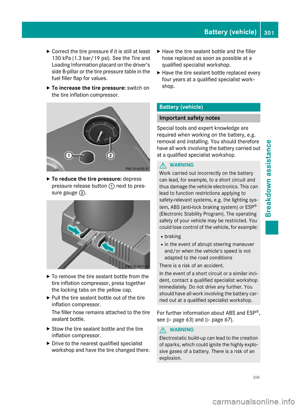
X To increase the tire pressure: switch on
the tire inflation compressor. X
To reduce the tire pressure: depress
pressure release button 0043next to pres-
sure gauge 0044. X
To remove the tire sealant bottle from the
tire inflation compressor, press together
the locking tabs on the yellow cap.
X Pull the tire sealant bottle out of the tire
inflation compressor.
The filler hose remains attached to the tire
sealant bottle.
X Stow the tire sealant bottle and the tire
inflation compressor.
X Drive to the nearest qualified specialist
workshop and have the tire changed there. X
Have the tire sealant bottle and the filler
hose replaced as soon as possible at a
qualified specialist workshop.
X Have the tire sealant bottle replaced every
four years at a qualified specialist work-
shop. Battery (vehicle)
Important safety notes
Special tools and expert knowledge are
required when working on the battery, e.g.
removal and installing. You should therefore
have all work involving the battery carried out
at a qualified specialist workshop. G
WARNING
Work carried out incorrectly on the battery
can lead, for example, to a short circuit and
thus damage the vehicle electronics. This can lead to function restrictions applying to
safety-relevant systems, e.g. the lighting sys-
tem, ABS (anti-lock braking system) or ESP ®
(Electronic Stability Program). The operating
safety of your vehicle may be restricted. You
could lose control of the vehicle, for example:
R braking
R in the event of abrupt steering maneuver
and/or when the vehicle's speed is not
adapted to the road conditions
There is a risk of an accident.
In the event of a short circuit or a similar inci- dent, contact a qualified specialist workshop
immediately. Do not drive any further. You
should have all work involving the battery car-
ried out at a qualified specialist workshop.
For further information about ABS and ESP ®
,
see (Y page 63) and (Y page 67). G
WARNING
Electrostatic build-up can lead to the creation of sparks, which could ignite the highly explo-
sive gases of a battery. There is a risk of an
explosion. Battery (vehicle)
301Breakdown assistance
Z
Page 309 of 358
Position number
0084identifies the charged battery of the other vehicle or an equivalent jump-
starting device.
X Press together cover 0043of positive clamp 0044and slide it back.
X Connect positive terminal 0044on your vehicle to positive terminal 0087of donor battery 0084
using the jumper cable, beginning with your own battery.
X Start the engine of the donor vehicle and run it at idling speed.
X Connect negative terminal 0085of donor battery 0084to ground point 0083of your vehicle using
the jumper cable, connecting the jumper cable to battery of other vehicle 0084first.
X Start the engine.
X Before disconnecting the jumper cables, let the engine run for several minutes.
X First, remove the jumper cables from ground point 0083and negative terminal 0085, then from
positive clamp 0044and positive terminal 0087. Begin each time at the contacts on your own
vehicle first.
X Close cover 0043of positive terminal 0044after removing the jumper cables.
X Have the battery checked at a qualified specialist workshop.
i Jump-starting is not considered to be a normal operating condition.
i Jumper cables and further information regarding jump-starting can be obtained at any
qualified specialist workshop. Towing and tow-starting
Important safety notes
G
WARNING
Functions relevant to safety are restricted or
no longer available if:
R the engine is not running.
R the brake system or the power steering is
malfunctioning.
R there is a malfunction in the voltage supply
or the vehicle's electrical system.
If your vehicle is being towed, much more
force may be necessary to steer or brake.
There is a risk of an accident.
In such cases, use a tow bar. Before towing,
make sure that the steering moves freely. G
WARNING
If the weight of the vehicle to be towed or tow- started is greater than the permissible gross
weight of your vehicle:
R the towing eye could detach itself
R the vehicle/trailer combination could roll-
over.
There is a risk of an accident.
When towing or tow-starting another vehicle,
its weight should not be greater than the per-
missible gross weight of your vehicle.
Information on your vehicle's gross vehicle
weight rating can be found on the vehicle
identification plate (Y page 346). Towing and tow-starting
307Breakdown assistance Z
Page 310 of 358
!
When COLLISION PREVENTION ASSIST
PLUS, DISTRONIC PLUS or the HOLD func- tion is activated, the vehicle brakes auto-
matically in certain situations. To avoid
damage to the vehicle, deactivate these
systems in the following or similar situa-
tions:
R when towing the vehicle
R in the car wash
! Only secure the tow rope or tow bar at the
towing eyes. Otherwise, the vehicle could
be damaged.
! Do not use the towing eyes for recovery
purposes as this could damage the vehicle.
If in doubt, recover the vehicle with a crane.
! When towing, pull away slowly and
smoothly. If the tractive power is too high,
the vehicles could be damaged.
! The vehicle can be towed a maximum of
30 miles (50km). The towing speed of
30 mph (50km/h) must not be exceeded.
If the vehicle has to be towed more than
30 miles (50km), the front axle must be
raised or the entire vehicle raised and
transported.
! Do not tow with sling-type equipment.
This could damage the vehicle.
! If you tow or tow-start another vehicle, its
weight must not exceed the maximum per- missible gross vehicle weight of your vehi-
cle.
! Vehicles with automatic transmission
must not be started by tow-starting. This
could otherwise damage the transmission.
It is better to have the vehicle transported
than to have it towed.
When towing a vehicle, the transmission must be in position N. The battery must be connected and charged.
Otherwise, you:
R cannot turn the SmartKey to position 2in
the ignition lock
R cannot shift the transmission to position N.
i Disarm the automatic locking feature
before the vehicle is towed (Y page 209).
You could otherwise be locked out when
pushing or towing the vehicle. Installing/removing the towing eye
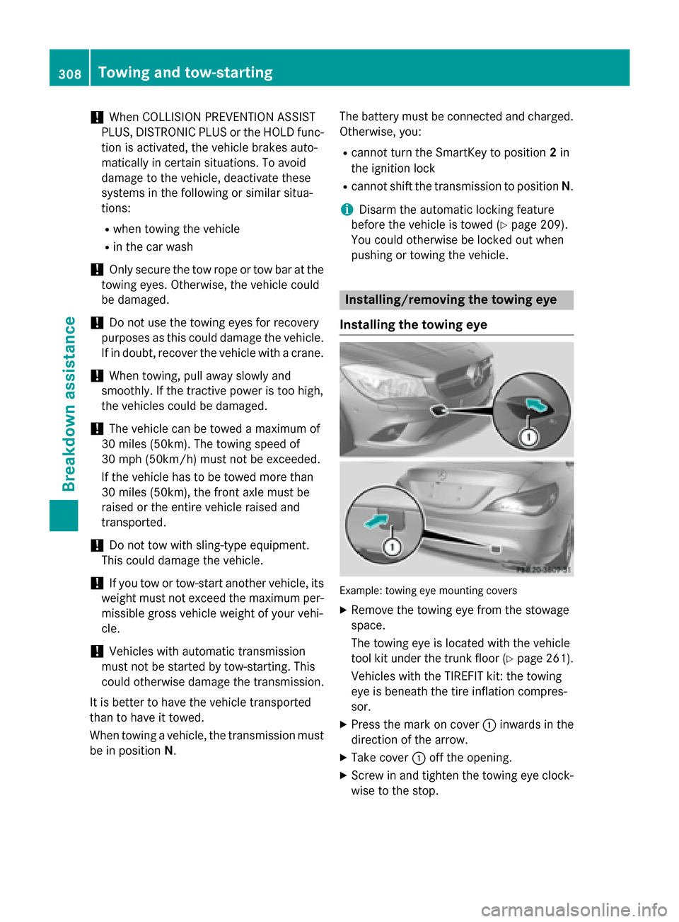
Installing the towing eye Example: towing eye mounting covers
X Remove the towing eye from the stowage
space.
The towing eye is located with the vehicle
tool kit under the trunk floor (Y page 261).
Vehicles with the TIREFIT kit: the towing
eye is beneath the tire inflation compres-
sor.
X Press the mark on cover 0043inwards in the
direction of the arrow.
X Take cover 0043off the opening.
X Screw in and tighten the towing eye clock-
wise to the stop. 308
Towing and tow-startingBreakdown assistance