lights MERCEDES-BENZ CLA-Class 2014 C117 Manual PDF
[x] Cancel search | Manufacturer: MERCEDES-BENZ, Model Year: 2014, Model line: CLA-Class, Model: MERCEDES-BENZ CLA-Class 2014 C117Pages: 358, PDF Size: 6.6 MB
Page 279 of 358
When indicator lamp
0043flashes green: pro-
graming was successful. The next step is to
synchronize the rolling code.
X Release button 0084of remote control 0083of
the garage door drive.
If indicator lamp 0043blinks red: repeat the
programing process for the corresponding
button on the rear-view mirror. When doing
so, vary the distance between remote con- trol 0083and the rear-view mirror.
The required distance between remote
control 0083and the integrated garage door
opener depends on the garage door drive
system. Several attempts might be neces-
sary. You should test every position for at
least 25 seconds before trying another
position.
Problems when programing
If you are experiencing problems programing
the integrated garage door opener on the
rear-view mirror, take note of the following
instructions:
R Check the transmitter frequency used by
garage door drive remote control 0083and
whether it is supported. The transmitter
frequency can usually be found on the back
of the garage door drive remote control.
The integrated garage door opener is com-
patible with devices that have units which
operate in the frequency range of 280 to
433 MHz.
R Replace the batteries in garage door
remote control 0083. This increases the like-
lihood that garage door remote control 0083
will transmit a strong and precise signal to
the integrated garage door opener in the
rear-view mirror.
R When programing, hold remote control 0083
at varying distances and angles from the
button that you are programing. Try various
angles at a distance between 2and
12 inches (5to 30 cm) or at the same angle
but at varying distances.
R If another remote control for the same
garage door drive is available, repeat the same programing steps with this remote
control. Before performing these steps,
make sure that new batteries have been
installed in garage door drive remote con-
trol
0083.
R Note that some remote controls only trans-
mit for a limited amount of time (the indi-
cator lamp on the remote control goes out).
Press button 0084on remote control 0083again
before transmission ends.
R Align the antenna cable of the garage door
opener unit. This can improve signal recep-tion/transmission.
Opening/closing the garage door After it has been programed, the integrated
garage door opener performs the function of
the garage door system remote control.
Please also read the operating instructions
for the garage door system.
X Turn the SmartKey to position 2in the igni-
tion lock (Y page 141).
X Press button 0044,0087or0085 which you have
programed to operate the garage door.
Garage door system with a fixed code: indi-
cator lamp 0043lights up green.
Garage door system with a rolling code:
indicator lamp 0043flashes green.
The transmitter will transmit a signal as long
as the button is pressed. The transmission is halted after a maximum of ten seconds and
indicator lamp 0043lights up yellow. Press but-
ton 0044, 0087or0085 again if necessary.
Clearing the memory Make sure that you clear the memory of the
integrated garage door opener before selling
the vehicle. Features
277Stowage and features Z
Page 280 of 358
X
Turn the SmartKey to position 2in the igni-
tion lock (Y page 141).
X Press and hold buttons 0044and 0085.
The indicator lamp initially lights up yellow
and then green.
X Release buttons 0044and 0085.
The memory of the integrated garage door
opener in the rear-view mirror is cleared. Compass
Calling up the compass The compass displays in which compass
direction the vehicle is currently traveling:
N N,
NE
NE, E
E,SE
SE, S
S,SW
SW, W
Wor NW
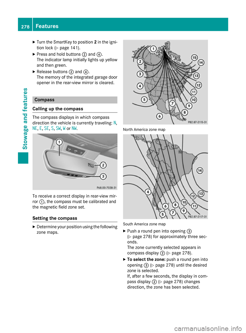
NW. To receive a correct display in rear-view mir-
ror 0043, the compass must be calibrated and
the magnetic field zone set.
Setting the compass X
Determine your position using the following
zone maps. North America zone map
South America zone map
X Push a round pen into opening 0087
(Y page 278) for approximately three sec-
onds.
The zone currently selected appears in
compass display 0044(Ypage 278).
X To select the zone: push a round pen into
opening 0087(Ypage 278) until the desired
zone is selected.
If, after a few seconds, the display in com-
pass display 0044(Ypage 278) changes
direction, the zone has been selected. 278
FeaturesStowage and features
Page 291 of 358
Power washers
G
WARNING
The water jet from a circular jet nozzle (dirt
blasters) can cause invisible exterior damage to the tires or chassis components. Compo-
nents damaged in this way may fail unexpect-edly. There is a risk of an accident.
Do not use power washers with circular jet
nozzles to clean the vehicle. Have damaged
tires or chassis components replaced imme-
diately.
! Always maintain a distance of at least
11.8 in (30 cm) between the vehicle and the
power washer nozzle. Information about
the correct distance is available from the
equipment manufacturer.
Move the power washer nozzle around
when cleaning your vehicle.
Do not aim directly at any of the following:
R tires
R door gaps, roof gaps, joints, etc.
R electrical components
R battery
R connectors
R lights
R seals
R trim
R ventilation slots
Damaged seals or electrical components
can lead to leaks or failures.
Cleaning the wheels !
Do not use acidic wheel cleaning products
to remove brake dust. This could damage
wheel bolts and brake components.
! Do not park the vehicle for an extended
period straight after cleaning it, particularly after having cleaned the wheels with wheel
cleaner. Wheel cleaners could cause
increased corrosion of the brake discs and
brake pads/linings. For this reason, you
should drive for a few minutes after clean- ing. Braking heats the brake discs and the
brake pads/linings, thus drying them. The
vehicle can then be parked.
Cleaning the paintwork !
Do not affix:
R stickers
R films
R magnetic plates or similar items
to painted surfaces. You could otherwise
damage the paintwork.
X Remove dirt immediately, where possible,
while avoiding rubbing too hard.
X Soak insect remains with insect remover
and rinse off the treated areas afterwards.
X Soak bird droppings with water and rinse
off the treated areas afterwards.
X Remove coolant, brake fluid, tree resin,
oils, fuels and greases by rubbing gently
with a cloth soaked in petroleum ether or
lighter fluid.
X Use tar remover to remove tar stains.
X Use silicone remover to remove wax.
X Use a suitable touch-up stick, e.g. MB
Touch-Up Stick, to repair slight damage to
the paintwork quickly and provisionally.
The following cannot always be completely
repaired:
R scratches
R corrosive deposits
R areas affected by corrosion
R damage caused by inadequate care
In such cases, visit a qualified specialist work-
shop.
If water no longer forms "beads" on the paint
surface, use the paint care products recom-
mended and approved by Mercedes-Benz.
This is the case approximately every three to
five months, depending on the climate con-
ditions and the care product used.
If the dirt has penetrated the paint surface or if the paintwork has become dull, then the
paintwork should be cleaned. For cleaning, Care
289Maintenance and care Z
Page 323 of 358
Loading Information placard on the B-pillar
on the driver's side of your vehicle.
X If necessary, increase the tire pressure to
the recommended value (Y page 317).
X If the tire pressure is too high, release air by
pressing down the metal pin in the valve
using the tip of a pen, for example. Then,
check the tire pressure again using the tire
pressure gauge.
X Screw the valve cap onto the valve.
X Repeat these steps for the other tires. Tire Pressure Monitor
General notes If a tire pressure monitor is installed, the vehi-
cle's wheels have sensors that monitor the
tire pressures in all four tires. The tire pres-
sure monitor warns you if the pressure drops
in one or more of the tires. The tire pressure
monitor only functions if the correct sensors
are installed on all wheels.
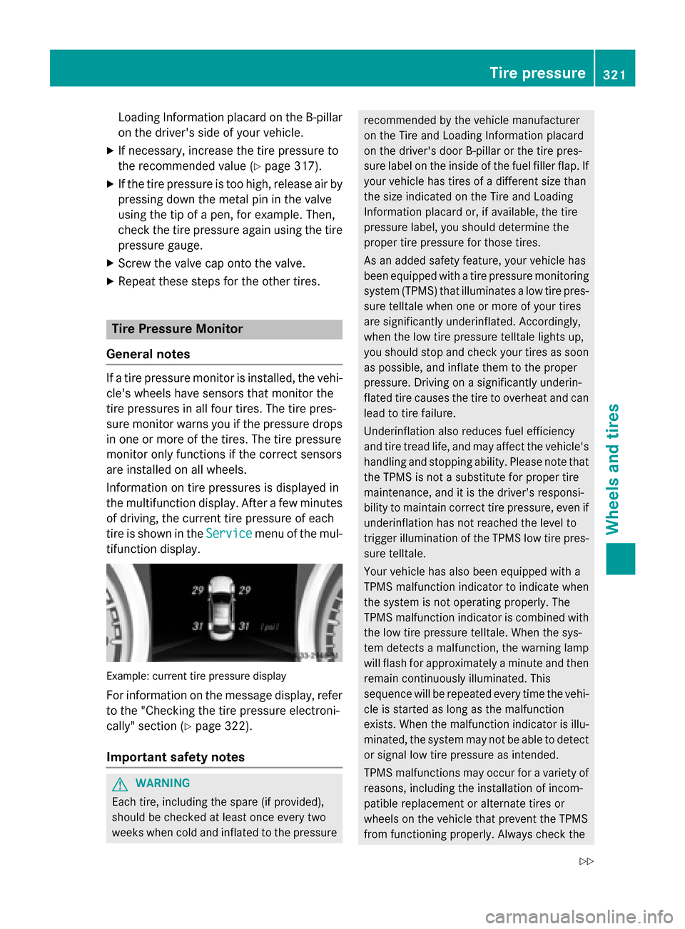
Information on tire pressures is displayed in
the multifunction display. After a few minutes of driving, the current tire pressure of each
tire is shown in the Service Servicemenu of the mul-
tifunction display. Example: current tire pressure display
For information on the message display, refer to the "Checking the tire pressure electroni-
cally" section (Y page 322).
Important safety notes G
WARNING
Each tire, including the spare (if provided),
should be checked at least once every two
weeks when cold and inflated to the pressure recommended by the vehicle manufacturer
on the Tire and Loading Information placard
on the driver's door B-pillar or the tire pres-
sure label on the inside of the fuel filler flap. If your vehicle has tires of a different size than
the size indicated on the Tire and Loading
Information placard or, if available, the tire
pressure label, you should determine the
proper tire pressure for those tires.
As an added safety feature, your vehicle has
been equipped with a tire pressure monitoring system (TPMS) that illuminates a low tire pres-
sure telltale when one or more of your tires
are significantly underinflated. Accordingly,
when the low tire pressure telltale lights up,
you should stop and check your tires as soon
as possible, and inflate them to the proper
pressure. Driving on a significantly underin-
flated tire causes the tire to overheat and can
lead to tire failure.
Underinflation also reduces fuel efficiency
and tire tread life, and may affect the vehicle's handling and stopping ability. Please note that
the TPMS is not a substitute for proper tire
maintenance, and it is the driver's responsi-
bility to maintain correct tire pressure, even if underinflation has not reached the level to
trigger illumination of the TPMS low tire pres-
sure telltale.
Your vehicle has also been equipped with a
TPMS malfunction indicator to indicate when
the system is not operating properly. The
TPMS malfunction indicator is combined with
the low tire pressure telltale. When the sys-
tem detects a malfunction, the warning lamp
will flash for approximately a minute and then remain continuously illuminated. This
sequence will be repeated every time the vehi-
cle is started as long as the malfunction
exists. When the malfunction indicator is illu- minated, the system may not be able to detect
or signal low tire pressure as intended.
TPMS malfunctions may occur for a variety of reasons, including the installation of incom-
patible replacement or alternate tires or
wheels on the vehicle that prevent the TPMS
from functioning properly. Always check the Tire pressure
321Wheels and tires
Z
Page 324 of 358
TPMS malfunction telltale after replacing one
or more tires or wheels on your vehicle to
ensure that the replacement or alternate Tires and wheels allow the TPMS to continue to
function properly.
It is the driver's responsibility to set the tire
pressure to that recommended for cold tires
which is suitable for the operating situation
(Y page 317). Note that the correct tire pres-
sure for the current operating situation must
first be taught-in to the tire pressure monitor.
If there is a substantial loss of pressure, the
warning threshold for the warning message is aligned to the reference values taught-in.
Restart the tire pressure monitor after adjust-
ing the pressure of the cold tires
(Y page 323). The current pressures are
saved as new reference values. As a result, a warning message will appear if the tire pres-
sure drops significantly.
The tire pressure monitor does not warn you
of an incorrectly set tire pressure. Observe
the notes on the recommended tire pressure
(Y page 317).
The tire pressure monitor is not able to warn
you of a sudden loss of pressure, e.g. if the
tire is penetrated by a foreign object. In the
event of a sudden loss of pressure, bring the
vehicle to a halt by braking carefully. Avoid
abrupt steering maneuvers.
The tire pressure monitor has a yellow warn-
ing lamp in the instrument cluster for indicat-
ing a pressure loss or malfunction. Whether
the warning lamp flashes or lights up indi-
cates whether a tire pressure is too low or the tire pressure monitor is malfunctioning:
R if the warning lamp is lit continuously, the
tire pressure on one or more tires is signif-
icantly too low. The tire pressure monitor is
not malfunctioning.
R if the warning lamp flashes for around a
minute and then remains lit constantly, the
tire pressure monitor is malfunctioning.
i In addition to the warning lamp, a mes-
sage appears in the multifunction display. Further information can be found on
(Y
page 237).
If the tire pressure monitor is malfunctioning,
it may take more than ten minutes for the tire pressure warning lamp to inform you of the
malfunction by flashing for approximately one
minute and then remaining lit. When the mal- function has been rectified, the tire pressure
warning lamp goes out after a few minutes of
driving.
The tire pressure values indicated by the on-
board computer may differ from those meas- ured at a gas station with a pressure gauge.
The tire pressures shown by the on-board
computer refer to those measured at sea
level. At high altitudes, the tire pressure val-
ues indicated by a pressure gauge are higher
than those shown by the on-board computer.
In this case, do not reduce the tire pressures.
The operation of the tire pressure monitor can
be affected by interference from radio trans-
mitting equipment (e.g. radio headphones,
two-way radios) that may be being operated
in or near the vehicle.
Checking the tire pressure electroni-
cally X
Make sure that the SmartKey is in position
2 in the ignition lock (Y page 141).
X Press the 0059or0065 button on the steer-
ing wheel to select the Service Servicemenu.
X Press the 0063or0064 button to select
Tire Pressure
Tire Pressure.
X Press the 0076button.
The current tire pressure of each tire is
shown in the multifunction display.
If the vehicle was parked for longer than
20 minutes, the Tire pressure will be
Tire pressure will be
displayed after driving a few displayed after driving a few
minutes minutes message is shown.
After a teach-in process, the tire pressure
monitor automatically detects new wheels or
new sensors. As long as a clear allocation of
the tire pressure value to the individual
wheels is not possible, the Tire Pressure Tire Pressure322
Tire pressureWheels and tires