tow bar MERCEDES-BENZ CLA-Class 2016 C117 Owner's Manual
[x] Cancel search | Manufacturer: MERCEDES-BENZ, Model Year: 2016, Model line: CLA-Class, Model: MERCEDES-BENZ CLA-Class 2016 C117Pages: 374, PDF Size: 8.19 MB
Page 20 of 374
Warning lamp ................................. 270
Warning message .......................... 338
TIREFIT kit .......................................... 312
Tire pressure not reached .............. 314
Tire pressure reached .................... 314
Tires
Aspect ratio (definition) ................. 350
Average weight of the vehicle
occupants (definition) .................... 349
Bar (definition) ...............................3 48
Changing a wheel .......................... 351
Characteristics .............................. 348
Checking ........................................ 329
Curb weight (definition) ................. 350
Definition of terms ......................... 348
Direction of rotation ...................... 351
Display message ............................ 250
Distribution of the vehicle occu-
pants (definition) ............................ 351
DOT (Department of Transporta-
tion) (definition) ............................. 349
DOT, Tire Identification Number
(TIN) ............................................... 348
GAWR (Gross Axle Weight Rating)
(definition) ..................................... 349
General notes ................................ 355
GVW (Gross Vehicle Weight) (def-
inition) ........................................... 349
GVWR (Gross Vehicle Weight Rat-
ing) (definition) .............................. 349
Important safety notes .................. 328
Increased vehicle weight due to
optional equipment (definition) ...... 349
Information on driving .................... 328
Kilopascal (kPa) (definition) ........... 349
Labeling (overview) ........................ 345
Load bearing index (definition) ...... 350
Load index ..................................... 347
Load index (definition) ................... 349
M+S tires ....................................... 330
Maximum load on a tire (defini-
tion) ............................................... 350
Maximum loaded vehicle weig ht
(
definition) ..................................... 349
Maximum permissible tire pres-
sure (definition) ............................. 350
Maximum tire load ......................... 347
Maximum tire load (definition) ....... 350 MOExtended tires .......................... 330
Optional equipment weight (defi-
nition) ............................................ 350
PSI (pounds per square inch) (def-
inition) ........................................... 350
Replacing ....................................... 351
Service life ..................................... 330
Sidewall (definition) ....................... 350
Speed rating (definition) ................ 349
Storing ........................................... 351
Structure and characteristics
(definition) ..................................... 348
Summer tires ................................. 330
Temperature .................................. 344
TIN (Tire Identification Number)
(definition) ..................................... 350
Tire bead (definition) ...................... 350
Tire pressure (definition) ................ 350
Tire pressures (recommended) ...... 349
Tire size (data) ............................... 355
Tire size designation, load-bearing
capacity, speed rating .................... 345
Tire tread ....................................... 329
Tire tread (definition) ..................... 350
Total load limit (definition) ............. 351
Traction ......................................... 344
Traction (definition) ....................... 350
Tread wear ..................................... 344
Uniform Tire Quality Grading
Standards ...................................... 343
Uniform Tire Quality Grading
Standards (definition) .................... 349
Wear indicator (definition) ............. 350
Wheel and tire combination ........... 357
Wheel rim (definition) .................... 349
see Flat tire
Top Tether ............................................ 61
Tow-starting
Emergency engine starting ............ 325
Important safety notes .................. 321
Installing the towing eye ................ 322
Removing the towing eye ............... 323
Towing a trailer
ESP®(Electronic Stability Pro-
gra m) ............................................... 72
To
wing away
Important safety guidelines ........... 321
Installing the towing eye ................ 322
18Index
Page 203 of 374
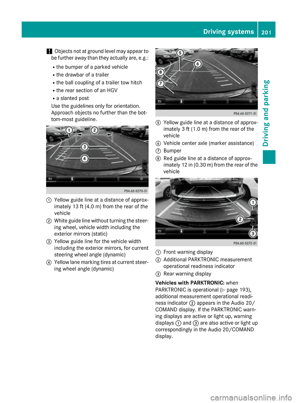
!Objects not at ground level may appear to
be further away than they actually are, e.g.:
Rthe bumper of a parked vehicle
Rthe drawbar of a trailer
Rthe ball coupling of a trailer tow hitch
Rthe rear section of an HGV
Ra slanted post
Use the guidelines only for orientation.
Approach objects no further than the bot-
tom-most guideline.
:Yellow guide line at a distance of approx-
imately 13 ft (4.0 m) from the rear of the
vehicle
;White guide line without turning the steer-
ing wheel, vehicle width including the
exterior mirrors (static)
=Yellow guide line for the vehicle width
including the exterior mirrors, for current
steering wheel angle (dynamic)
?Yellow lane marking tires at current steer-
ing wheel angle (dynamic)
AYellow guide line at a distance of approx-
imately 3 ft (1.0 m) from the rear of the
vehicle
BVehicle center axle (marker assistance)
CBumper
DRed guide line at a distance of approx-
imately 12 in (0.30 m) from the rear of the
vehicle
:Front warning display
;Additional PARKTRONIC measurement
operational readiness indicator
=Rear warning display
Vehicles with PARKTRONIC: when
PARKTRONIC is operational (
Ypage 193),
additional measurement operational readi-
ness indicator ;appears in the Audio 20/
COMAND display. If the PARKTRONIC warn-
ing displays are active or light up, warning
displays :and =are also active or light up
correspondingly in the Audio 20/COMAND
display.
Driving systems201
Driving and parking
Z
Page 315 of 374
!Do not operate the tire inflation compres-
sor for longer than ten minutes at a time
without a break. It may otherwise overheat.
The tire inflation compressor can be oper-
ated again once it has cooled down.
Comply with the manufacturer’s safety
instructions on the sticker on the tire inflation
compressor.
Using the TIREFIT kit
XDo not remove any foreign objects which
have penetrated the tire, e.g. screws or
nails.
XRemove the tire sealant bottle, the accom-
panying TIREFIT sticker and the tire infla-
tion compressor from the stowage well
underneath the trunk floor (
Ypage 310).
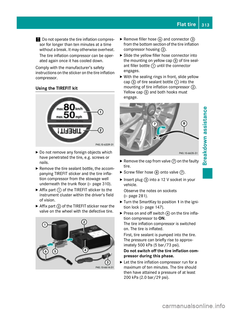
XAffix part :of the TIREFIT sticker to the
instrument cluster within the driver's field
of vision.
XAffix part ;of the TIREFIT sticker near the
valve on the wheel with the defective tire.
XRemove filler hose Band connector =
from the bottom section of the tire inflation
compressor housing ;.
XSlide the yellow filler hose connector into
the mounting on yellow cap Aof tire seal-
ant filler bottle :until the connector
engages.
XWith the sealing rings in front, slide yellow
cap Aof tire sealant bottle :into the
mounting of tire inflation compressor ;.
Yellow cap Aand both hooks must
engage.
XRemove the cap from valve Con the faulty
tire.
XScrew filler hose Donto valve C.
XInsert plug =into a 12 V socket in your
vehicle.
Observe the notes on sockets
(
Ypage 281).
XTurn the SmartKey to position 1in the igni-
tion lock (
Ypage 147).
XPress on and off switch ?on the tire infla-
tion compressor to ON.
The tire inflation compressor is switched
on. The tire is inflated.
First, tire sealant is pumped into the tire.
The pressure can briefly rise to approx-
imately 500 kPa (5 bar/73 psi).
Do not switch off the tire inflation com-
pressor during this phase.
XLet the tire inflation compressor run for a
maximum of ten minutes. The tire should
then have attained a pressure of at least
200 kPa (2.0 bar/29 psi).
Flat tire313
Breakdown assistance
Z
Page 316 of 374

If a pressure of 200 kPa (2.0 bar/29 psi) has
been attained after five minutes, see "Tire
pressure reached" (
Ypage 314).
If a tire pressure of 200 kPa (2.0 bar/29 psi)
has not been attained after five minutes, see
"Tire pressure not reached" (
Ypage 314).
If tire sealant has escaped, clean it off affec-
ted areas as quickly as possible. Use plain
water if possible.
If your clothes are soiled with tire sealant,
have them cleaned with perchloroethylene at
a dry cleaner as soon as possible.
Tire pressure not reached
If a tire pressure of 200 kPa (2.0 bar/29 psi)
has not been attained after ten minutes:
XSwitch off the tire inflation compressor.
XUnscrew the filler hose from the valve of
the faulty tire.
Note that tire sealant may escape when you unscrew the filler hose.
XVery slowly drive forwards or reverse
approximately 30 ft (10 m).
XPump up the tire again.
After a maximum of ten minutes, the tire
pressure must be at least 200 kPa (2.0 bar/29 psi).
GWARNING
If the required tire pressure is not reached
after the specified time, the tire is too badly
damaged. The tire sealant cannot repair the
tire in this instance. Damaged tires and a tire
pressure that is too low can significantly
impair the vehicle's braking and driving char-
acteristics. There is a risk of accident.
Do not continue driving. Contact a qualified
specialist workshop.
Tire pressure reached
GWARNING
A tire temporarily sealed with tire sealant
impairs the driving characteristics and is not
suitable for higher speeds. There is a risk of
accident.
You should therefore adapt your driving style
accordingly and drive carefully. Do not exceed the specified maximum speed with a tire that
has been repaired using tire sealant.
The maximum permissible speed for a tire
sealed with tire sealant is 50 mph (80 km/h). The upper part of the TIREFIT sticker must be
affixed to the instrument cluster in the driv-
er's field of vision.
!Residue from the tire sealant may come
out of the filler hose after use. This could
cause stains.
Therefore, place the filler hose in the plastic
bag which contained the TIREFIT kit.
HEnvironmental note
Have the used tire sealant bottle disposed of
professionally, e.g. at a qualified specialist
workshop.
If a tire pressure of 200 kPa (2.0 bar/29 psi)
has been attained after ten minutes:
XSwitch off the tire inflation compressor.
XUnscrew the filler hose from the valve of
the faulty tire.
XStow the tire sealant bottle and the tire
inflation compressor.
XPull away immediately.
XStop after driving for approximately ten
minutes and check the tire pressure with
the tire inflation compressor.
The tire pressure must now be at least
130 kPa (1.3 bar/19 psi).
GWARNING
If the required tire pressure is not reached
after driving for a short period, the tire is too
badly damaged. The tire sealant cannot repair
the tire in this instance. Damaged tires and a
tire pressure that is too low can significantly
impair the vehicle's braking and driving char-
acteristics. There is a risk of accident.
314Flat tire
Breakdown assistance
Page 323 of 374
XStart the engine of the donor vehicle and run it at idling speed.
XConnect negative terminal?of donor battery Bto ground point Aof your vehicle using
the jumper cable, connecting the jumper cable to battery of other vehicle Bfirst.
XIf the battery is fully discharged, leave the battery that is being used to jump-start connected
for a few minutes before attempting to start. This charges the battery slightly.
XStart the engine.
XBefore disconnecting the jumper cables, let the engine run for several minutes.
XFirst, remove the jumper cables from ground point Aand negative terminal ?, then from
positive clamp ;and positive terminal =. Begin each time at the contacts on your own
vehicle first.
XClose cover :of positive terminal ;after removing the jumper cables.
XClose the hood.
XHave the battery checked at a qualified specialist workshop.
iJump-starting is not considered to be a normal operating condition.
iJumper cables and further information regarding jump-starting can be obtained at any
qualified specialist workshop.
Towing and tow-starting
Important safety notes
GWARNING
Functions relevant to safety are restricted or
no longer available if:
Rthe engine is not running.
Rthe brake system or the power steering is
malfunctioning.
Rthere is a malfunction in the voltage supply or the vehicle's electrical system.
If your vehicle is being towed, much more
force may be necessary to steer or brake.
There is a risk of an accident.
In such cases, use a tow bar. Before towing,
make sure that the steering moves freely.
GWARNING
You can no longer steer the vehicle if the
steering wheel lock has been engaged. There
is a risk of an accident.
Always switch off the ignition when towing the
vehicle with a tow cable or a tow bar.
GWARNING
When towing or tow-starting another vehicle
and its weight is greater than the permissible
gross weight of your vehicle, the:
Rthe towing eye could detach itself
Rthe vehicle/trailer combination could roll-
over.
There is a risk of an accident.
When towing or tow-starting another vehicle,
its weight should not be greater than the per- missible gross weight of your vehicle.
Details on the permissible gross vehicle
weight of your vehicle can be found on the
vehicle identification plate (
Ypage 364).
!When COLLISION PREVENTION ASSIST
PLUS, DISTRONIC PLUS or the HOLD func-
tion is activated, the vehicle brakes auto-
matically in certain situations. To avoid
damage to the vehicle, deactivate these
systems in the following or similar situa-
tions:
Rwhen towing the vehicle
Rin the car wash
Towing and tow-starting321
Breakdown assistance
Z
Page 324 of 374
!Make sure that the electric parking brake
is released. If the electric parking brake is
faulty, visit a qualified specialist workshop.
!Only secure the tow rope or tow bar at the
towing eyes. Otherwise, the vehicle could
be damaged.
!Do not use the towing eyes for recovery
purposes as this could damage the vehicle. If in doubt, recover the vehicle with a crane.
!When towing, pull away slowly and
smoothly. If the tractive power is too high,
the vehicles could be damaged.
!The vehicle can be towed a maximum of
30 miles (50km). The towing speed of
30 mph (50km/h) must not be exceeded.
If the vehicle has to be towed more than
30 miles (50km), the front axle must be
raised or the entire vehicle raised and
transported.
!Do not tow with sling-type equipment.
This could damage the vehicle.
!When towing vehicles with KEYLESS-GO,
use the key instead of the Start/Stop but-
ton. Otherwise, the automatic transmission
may shift to position Pwhen the driver's or
front-passenger door are opened, which
could lead to damage to the transmission.
!Vehicles with automatic transmission
must not be started by tow-starting. This
could otherwise damage the transmission.
It is better to have the vehicle transported
than to have it towed away.
If the vehicle can no longer be driven because of an accident or breakdown, you have the
following options:
RTransporting the vehicle
As a rule, you should have the vehicle trans-
ported.
RTowing the vehicle with a tow rope or tow
bar
Only tow the vehicle in exceptional cases. The battery must be connected and charged.
Otherwise, you:
Rcannot turn the SmartKey to position 2in
the ignition lock
Rcannot release the electric parking brake
Rcannot shift the transmission to position N
The function of the electric parking brake and the parking lock is dependent on the on-board
voltage.
If the on-board voltage is low or there is a
system malfunction, it is possible that:
Rthe electric parking brake may not be
applied in certain circumstances, or
Rthe transmission may not be shifted to P
Switch off non-essential consumers, e.g. the
radio.
Disarm the automatic locking feature before
the vehicle is towed (
Ypage 222). You could
otherwise be locked out when pushing or
towing the vehicle.
Installing/removing the towing eye
Installing the towing eye
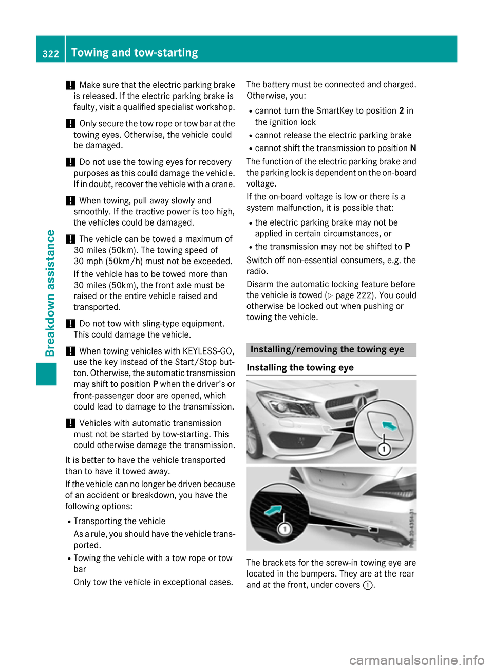
The brackets for the screw-in towing eye are
located in the bumpers. They are at the rear
and at the front, under covers :.
322Towing and tow-starting
Breakdown assistance
Page 357 of 374
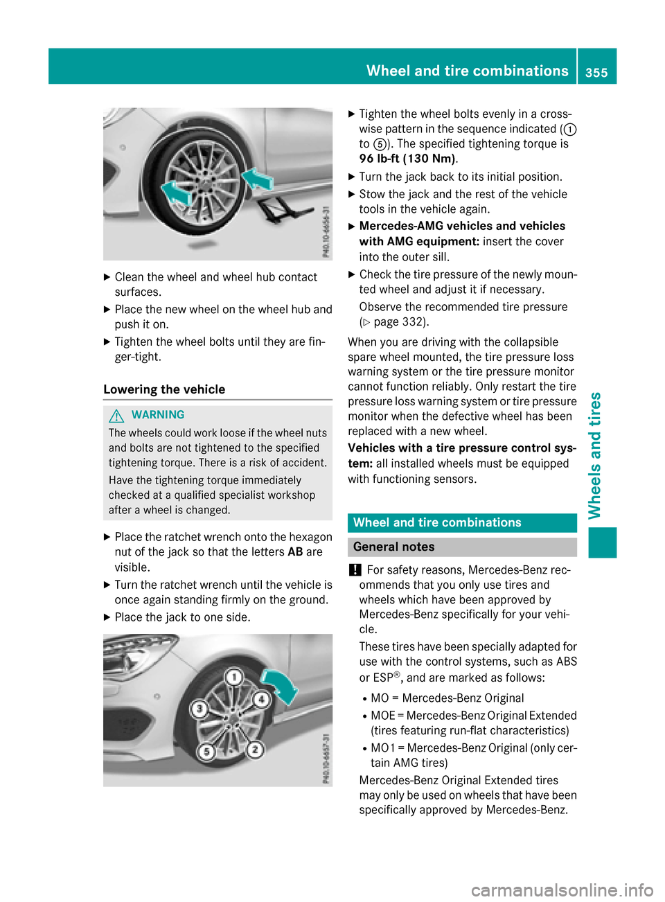
XClean the wheel and wheel hub contact
surfaces.
XPlace the new wheel on the wheel hub andpush iton.
XTighten the wheel bolts unt ilthey are fin-
ger-tight.
Lowering the vehicle
GWARNIN G
The wheels could work loos eif th ewhee lnut s
and bolt sare no ttightened to th especifie d
tightening torque .Ther eis aris kof accident.
Hav eth etightening torque immediately
checked at aqualified specialist worksho p
after awhee lis changed.
XPlace the ratchet wrench onto the hexagon
nut of the jack so that the letters ABare
vis ible.
XTurn the ratchet wrench unt ilthe vehicle is
once again standing firmly on the ground.
XPlace the jack to one side.
XTighten the wheel bolts evenly ina cross-
wise pattern inthe sequence indicated ( :
to A). The specified tightening torque is
96 lb-ft (130 Nm).
XTurn the jack back to its initial position.
XStow the jack and the rest of the vehicle
tools inthe veh icleagain.
XMercedes-AMG vehicles and vehicles
with AMG equipment: insert the cover
into the outer sill.
XCheck the tire pressure of the newly moun-
ted wheel and adjust it ifnecessary.
Observe the recommended tire pressure
(
Ypage 332).
When you are driving with the co llapsible
spare wheel mounte d,the tire pressure loss
warning system or the tire pressure monitor
cannot function reliably. Only restart the tire
pressure loss warning system or tire pressure
mon itor when the defective wheel has been
replaced with a new wheel.
Vehicles with a tire pressure controlsys-
tem: all installed wheels must be equipped
with functioning sensors.
Wheel and tire combinations
General notes
!
For safety reasons, Mercedes-Benz rec-
ommends that you only use tires and
wheels which have been approved by
Mercedes-Benz specific ally for your vehi-
cle.
These tires have been specially adapted for
use with the control systems, such as ABS
or ESP
®, and are marked as follows:
RMO = Mercedes-Benz Original
RMOE = Mercedes-Benz Original Extended
(t ires featuring run-flat characteristics)
RMO1 = Mercedes-Benz Original (only cer-
tain AMG tires)
Mercedes-Benz Original Extended tires
may only be used on wheels that have been
specific ally approved byMercedes-Benz.
Wheel and tire combinations355
Wheels and tires
Z