service indicator MERCEDES-BENZ CLA-Class 2017 C117 Owner's Manual
[x] Cancel search | Manufacturer: MERCEDES-BENZ, Model Year: 2017, Model line: CLA-Class, Model: MERCEDES-BENZ CLA-Class 2017 C117Pages: 318, PDF Size: 8.02 MB
Page 4 of 318
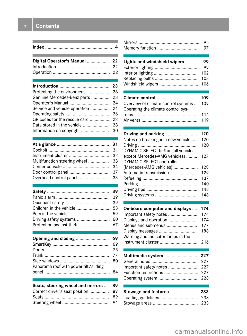
Index....................................................... 4
Digital Operator's Manual..................22
Introduction .......................................... .22
Operation ............................................... 22
Introduction ......................................... 23
Protecting the environment ...................2 3
Genuine Mercedes-Benz parts .............. .23
Operator's Manual ................................. 24
Service and vehicle operation ................2 4
Operating safety .................................... 26
QR codes for the rescue card ................2 8
Data stored in the vehicle ...................... 28
Information on copyright ....................... 30
At a glance ........................................... 31
Cockpit .................................................. 31
Instrument cluster ................................. 32
Multifunction steering wheel ................. 33
Center console ...................................... 34
Door control panel ................................. 37
Overhead control panel .........................3 8
Safety................................................... 39
Panic alarm ............................................ 39
Occupant safety .................................... 39
Children in the vehicle ........................... 53
Pets in the vehicle ................................. 59
Driving safety systems ........................... 60
Protection against theft .........................6 7
Opening and closing...........................69
SmartKey ............................................... 69
Doors ..................................................... 75
Trunk ..................................................... 77
Side windows ......................................... 80
Panorama roof with power tilt/sliding
panel ...................................................... 84
Seats, steering wheel and mirrors ....89
Correct driver's seat position ............... .89
Seats ..................................................... 89
Steering wheel ....................................... 94 Mirrors ................................................... 95
Memory function ................................... 97
Lights and windshield wipers
............99
Exterior lighting ..................................... 99
Interior lighting .................................... 102
Replacing bulbs ................................... 103
Windshield wipers ................................ 106
Climate control ................................. 109
Overview of climate control systems ... 109
Operating the climate control sys-
tems .................................................... 114
Air vents .............................................. 119
Driving and parking ..........................120
Notes on breaking-in a new vehicle ..... 120
Driving ................................................. 120
DYNAMIC SELECT button (all vehicles
except Mercedes-AMG vehicles) ......... 127
DYNAMIC SELECT controller
(Mercedes-AMG vehicles) .................... 128
Automatic transmission ....................... 129
Refueling ............................................. 137
Parking ................................................ 140
Driving tips .......................................... 143
Driving systems ................................... 148
On-board computer and displays ....174
Important safety notes ........................ 174
Displays and operation ........................ 174
Menus and submenus ......................... 177
Display messages ................................ 188
Warning and indicator lamps in the
instrument cluster ............................... 216
Multimedia system ...........................227
General notes ...................................... 227
Important safety notes ........................ 227
Function restrictions ............................ 227
Operating system ................................ 228
Stowage and features ......................233
Loading guidelines ............................... 233
Stowage areas ..................................... 233
2Contents
Page 6 of 318
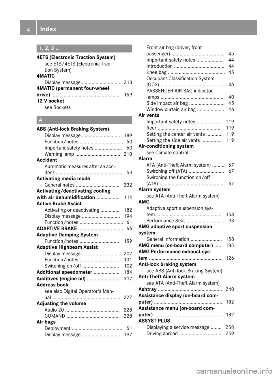
1, 2, 3 ...
4ETS (Electronic Traction System)see ETS/4ETS (Electronic Trac-
tion System)
4MATIC
Display message ............................ 213
4MATIC (permanent four-wheel
drive) .................................................. 159
12 V socket
see Sockets
A
ABS (Anti-lock Braking System)Display message ............................ 189
Function/notes ................................ 60
Important safety notes .................... 60
Warning lamp .................................2 18
Accident
Automatic measures after an acci-
dent ................................................. 53
Activating media mode
General notes ................................ 232
Activating/deactivating cooling
with air dehumidification ................. 114
Active Brake Assist
Activating or deactivating .............. 182
Display message ............................ 194
Function/notes ................................ 61
ADAPTIVE BRAKE ................................. 66
Adaptive Damping System
Function/notes .............................1 59
Adaptive Highbeam Assist
Display message ............................ 202
Function/notes .............................1 01
Switching on/off ........................... 102
Additional speedometer ................... 184
Additives (engine oil) ........................ 312
Address book
see also Digital Operator's Man-
ual ..................................................2 27
Adjusting the volume
Audio 20 ........................................ 228
COMAND ....................................... 228
Air bags
Deployment ..................................... 51
Display message ............................ 197 Front air bag (driver, front
passenger) ....................................... 45
Important safety notes .................... 44
Introduction ..................................... 44
Knee bag .......................................... 45
Occupant Classification System
(OCS) ............................................... 46
PASSENGER AIR BAG indicator
lamps ............................................... 40
Side impact air bag .......................... 45
Window curtain air bag .................... 46
Ai r ve
nts
Important safety notes .................. 119
Rear ............................................... 119
Setting the center air vents ........... 119
Setting the side air vents ...............1 19
Air-conditioning system
see Climate control
Alarm
ATA (Anti-Theft Alarm system) ......... 67
Switching off (ATA) .......................... 67
Switching the function on/off
(ATA) ................................................ 67
Alarm system
see ATA (Anti-Theft Alarm system)
AMG
Adaptive sport suspension sys-
tem ................................................ 158
Performance Seat ............................ 93
AMG adaptive sport suspension
system
General Information ....................... 158
AMG menu (on-board computer) ..... 185
AMG Performance exhaust sys-
tem ..................................................... 126
Anti-lock braking system
see ABS (Anti-lock Braking System)
Anti-Theft Alarm system
see ATA (Anti-Theft Alarm system)
Ashtray ............................................... 240
Assistance display (on-board com-
puter) ..................................................1 82
Assistance menu (on-board com-
puter) ..................................................1 82
ASSYST PLUS
Displaying a service message ........2 58
Driving abroad ............................... 259
4Index
Page 21 of 318
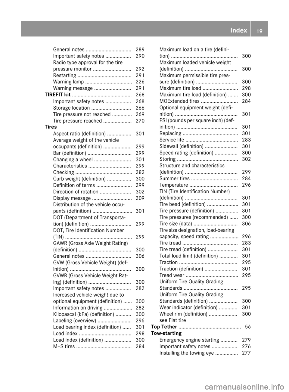
General notes ................................ 289
Important safety notes .................. 290
Radio type approval for the tire
pressure monitor ...........................292
Restarting ...................................... 291
Warning lamp ................................. 226
Warning message .......................... 291
TIREFIT kit .......................................... 268
Important safety notes .................. 268
Storage location ............................ 266
Tire pressure not reached .............. 269
Tire pressure reached .................... 270
Tires
Aspect ratio (definition) ................. 301
Average weight of the vehicle
occupants (definition) .................... 299
Bar (definition) ............................... 299
Changing a wheel .......................... 301
Characteristics .............................. 299
Checking ........................................ 282
Curb weight (definition) ................. 300
Definition of terms ......................... 299
Direction of rotation ...................... 302
Display message ............................ 209
Distribution of the vehicle occu-
pants (definition) ............................ 301
DOT (Department of Transporta-
tion) (definition) ............................. 299
DOT, Tire Identification Number
(TIN) ............................................... 299
GAWR (Gross Axle Weight Rating)
(definition) ..................................... 300
General notes ................................ 306
GVW (Gross Vehicle Weight) (def-
inition) ........................................... 300
GVWR (Gross Vehicle Weight Rat-
ing) (definition) .............................. 300
Important safety notes .................. 282
Increased vehicle weight due to
optional equipment (definition) ...... 300
Information on driving .................... 282
Kilopascal (kPa) (definiti on) ........... 300
La
beling (overview) ........................ 296
Load bearing index (definition) ...... 301
Load index ..................................... 298
Load index (definition) ................... 300
M+S tires ....................................... 284 Maximum load on a tire (defini-
tion) ............................................... 300
Maximum loaded vehicle weight
(definition) ..................................... 300
Maximum permissible tire pres-
sure (definition) ............................. 300
Maximum tire load ......................... 298
Maximum tire load (definition) ....... 300
MOExtended tires .......................... 284
Optional equipment weight (defi-
nition) ............................................ 301
PSI (pounds per square inch) (def-
inition) ........................................... 301
Replacing ....................................... 301
Service life ..................................... 283
Sidewall (definition) ....................... 301
Speed rating (definition) ................ 300
Storing ........................................... 302
Structure and characteristics
(definition) ..................................... 299
Summer tires ................................. 284
Temperature .................................. 296
TIN (Tire Identification Number)
(definition) ..................................... 301
Tire bead (definition) ...................... 301
Tire pressure (definition) ................ 301
Tire pressures (recommended) ...... 300
Tire size (data) ............................... 306
Tire size designation, load-bearing
capacity, speed rating .................... 296
Tire tread ....................................... 283
Tire tread (definition) ..................... 301
Total load limit (definition) ............. 301
Traction ......................................... 295
Traction (definition) ....................... 301
Tread wear ..................................... 295
Uniform Tire Quality Grading
Standards ...................................... 295
Uniform Tire Quality Grading
Standards (definition) .................... 300
Wear indicator (definition) ............. 301
Wheel rim (definition) .................... 300
see Fla
t ti
re
Top Tether ............................................ 56
Tow-starting
Emergency engine starting ............ 279
Important safety notes .................. 276
Installing the towing eye ................ 277
Index19
Page 110 of 318

XSlide catch;in the direction of arrow =
until it engages in the locking position with a
noticeable click.
XMake sure that the wiper blade is seated cor-
rectly.
XFold the wiper arm back onto the windshield.
XRemove protective film :of the service indi-
cator on the tip of the wiper blade.
If the color of the service indicator changes from
black to yellow, the wiper blades should be
replaced.
iThe duration of the color change varies
depending on the usage conditions.
Problems with the windshield wipers
ProblemPossible causes/consequences and MSolutions
The windshield wipers
are jammed.Leaves or snow, for example, may be obstructing the windshield wiper
movement. The wiper motor has been deactivated.
XFor safety reasons, you should remove the SmartKey from the igni-
tion lock.
XRemove the cause of the obstruction.
XSwitch the windshield wipers back on.
The windshield wipers
fail completely.The windshield wiper drive is malfunctioning.
XSelect another wiper speed on the combination switch.
XHave the windshield wipers checked at a qualified specialist work-
shop.
The windshield washer
fluid from the spray noz-
zles no longer hits the
center of the windshield.The spray nozzles are misaligned.
XHave the spray nozzles adjusted at a qualified specialist workshop.
108Windshield wipers
Lights and windshield wipers
Page 173 of 318
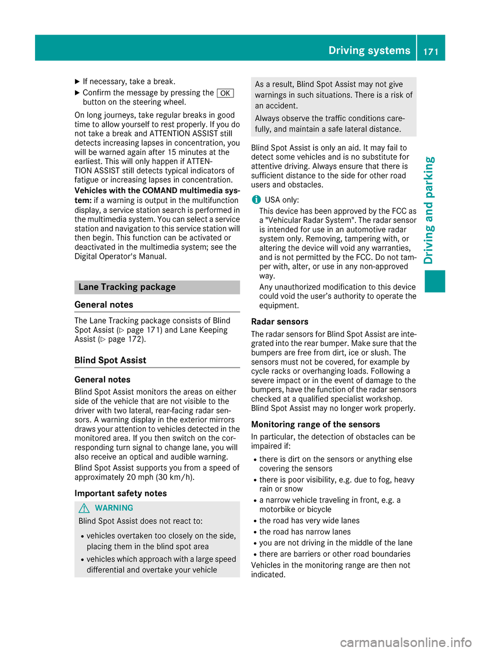
XIf necessary, take a break.
XConfirm the message by pressing thea
button on the steering wheel.
On long journeys, take regular breaks in good
time to allow yourself to rest properly. If you do
not take a break and ATTENTION ASSIST still
detects increasing lapses in concentration, you
will be warned again after 15 minutes at the
earliest. This will only happen if ATTEN-
TION ASSIST still detects typical indicators of
fatigue or increasing lapses in concentration.
Vehicles with the COMAND multimedia sys-
tem: if a warning is output in the multifunction
display, a service station search is performed in
the multimedia system. You can select a service
station and navigation to this service station will
then begin. This function can be activated or
deactivated in the multimedia system; see the
Digital Operator's Manual.
Lane Tracking package
General notes
The Lane Tracking package consists of Blind
Spot Assist (Ypage 171) and Lane Keeping
Assist (Ypage 172).
Blind Spot Assist
General notes
Blind Spot Assist monitors the areas on either
side of the vehicle that are not visible to the
driver with two lateral, rear-facing radar sen-
sors. A warning display in the exterior mirrors
draws your attention to vehicles detected in the
monitored area. If you then switch on the cor-
responding turn signal to change lane, you will
also receive an optical and audible warning.
Blind Spot Assist supports you from a speed of
approximately 20 mph (30 km/h).
Important safety notes
GWARNING
Blind Spot Assist does not react to:
Rvehicles overtaken too closely on the side,
placing them in the blind spot area
Rvehicles which approach with a large speed
differential and overtake your vehicle
As a result, Blind Spot Assist may not give
warnings in such situations. There is a risk of
an accident.
Always observe the traffic conditions care-
fully, and maintain a safe lateral distance.
Blind Spot Assist is only an aid. It may fail to
detect some vehicles and is no substitute for
attentive driving. Always ensure that there is
sufficient distance to the side for other road
users and obstacles.
iUSA only:
This device has been approved by the FCC as
a "Vehicular Radar System". The radar sensor
is intended for use in an automotive radar
system only. Removing, tampering with, or
altering the device will void any warranties,
and is not permitted by the FCC. Do not tam-
per with, alter, or use in any non-approved
way.
Any unauthorized modification to this device
could void the user’s authority to operate the
equipment.
Radar sensors
The radar sensors for Blind Spot Assist are inte-
grated into the rear bumper. Make sure that the
bumpers are free from dirt, ice or slush. The
sensors must not be covered, for example by
cycle racks or overhanging loads. Following a
severe impact or in the event of damage to the
bumpers, have the function of the radar sensors
checked at a qualified specialist workshop.
Blind Spot Assist may no longer work properly.
Monitoring range of the sensors
In particular, the detection of obstacles can be
impaired if:
Rthere is dirt on the sensors or anything else
covering the sensors
Rthere is poor visibility, e.g. due to fog, heavy
rain or snow
Ra narrow vehicle traveling in front, e.g. a
motorbike or bicycle
Rthe road has very wide lanes
Rthe road has narrow lanes
Ryou are not driving in the middle of the lane
Rthere are barriers or other road boundaries
Vehicles in the monitoring range are then not
indicated.
Driving systems171
Driving and parking
Z
Page 244 of 318
Socket in the rear compartment center
console
XPull the cover out by the top of the handle
edge.
XLift up the cover of the socket.
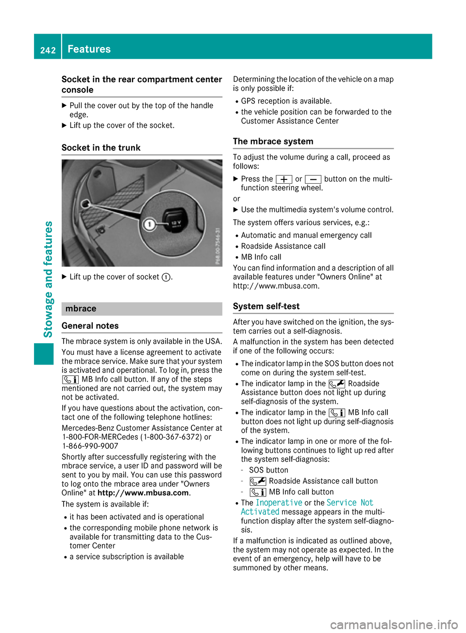
Socket in the trunk
XLift up the cover of socket:.
mbrace
General notes
The mbrace system is only available in the USA.
You must have a license agreement to activate
the mbrace service. Make sure that your system
is activated and operational. To log in, press the
ï MB Info call button. If any of the steps
mentioned are not carried out, the system may
not be activated.
If you have questions about the activation, con-
tact one of the following telephone hotlines:
Mercedes-Benz Customer Assistance Center at
1-800-FOR-MERCedes (1-800-367-6372) or
1-866-990-9007
Shortly after successfully registering with the
mbrace service, a user ID and password will be
sent to you by mail. You can use this password
to log onto the mbrace area under "Owners
Online" at http://www.mbusa.com.
The system is available if:
Rit has been activated and is operational
Rthe corresponding mobile phone network is
available for transmitting data to the Cus-
tomer Center
Ra service subscription is available Determining the location of the vehicle on a map
is only possible if:
RGPS reception is available.
Rthe vehicle position can be forwarded to the
Customer Assistance Center
The mbrace system
To adjust the volume during a call, proceed as
follows:
XPress the
WorX button on the multi-
function steering wheel.
or
XUse the multimedia system's volume control.
The system offers various services, e.g.:
RAutomatic and manual emergency call
RRoadside Assistance call
RMB Info call
You can find information and a description of all
available features under "Owners Online" at
http://www.mbusa.com.
System self-test
After you have switched on the ignition, the sys-
tem carries out a self-diagnosis.
A malfunction in the system has been detected if one of the following occurs:
RThe indicator lamp in the SOS button does notcome on during the system self-test.
RThe indicator lamp in the FRoadside
Assistance button does not light up during
self-diagnosis of the system.
RThe indicator lamp in the ïMB Info call
button does not light up during self-diagnosis
of the system.
RThe indicator lamp in one or more of the fol-
lowing buttons continues to light up red after
the system self-diagnosis:
-SOS button
-F Roadside Assistance call button
-ïMB Info call button
RTheInoperativeor the Service NotActivatedmessage appears in the multi-
function display after the system self-diagno-
sis.
If a malfunction is indicated as outlined above,
the system may not operate as expected. In the event of an emergency, help will have to be
summoned by other means.
242Features
Stowage and features
Page 245 of 318
Have the system checked at the nearest
Mercedes-Benz Service Center or contact the
following service hotlines:
Mercedes-Benz Customer Assistance Center at
1-800-FOR-MERCedes(1-800-367-6372) or
1-866-990-9007
Emergency call
Important safety notes
GWARNING
It can be dangerous to remain in the vehicle,
even if you have pressed the SOS button in an emergency if:
Ryou see smoke inside or outside of the vehi-
cle, e.g. if there is a fire after an accident
Rthe vehicle is on a dangerous section of
road
Rthe vehicle is not visible or cannot easily beseen by other road users, particularly when
dark or in poor visibility conditions
There is a risk of an accident and injury.
Leave the vehicle immediately in this or simi-
lar situations as soon as it is safe to do so.
Move to a safe location along with other vehi-
cle occupants. In such situations, secure the
vehicle in accordance with national regula-
tions, e. g. with a warning triangle.
General notes
Observe the notes on system activation
(Ypage 242).
An emergency call is dialed automatically if an
air bag or Emergency Tensioning Device is trig-
gered. You cannot end an automatically trig-
gered emergency call yourself.
An emergency call can also be initiated man-
ually.
As soon as the emergency call has been initi-
ated, the indicator lamp in the SOS button
flashes. The Connecting Call
message
appears in the multifunction display.
The audio output is muted.
Once the connection has been made, the Call
Connectedmessage appears in the multifunc-
tion display. All important information on the emergency is
transmitted, for example:
Rcurrent location of the vehicle (as determined
by the GPS system)
Rvehicle identification number
Rinformation on the severity of the accident
Shortly after the emergency call has been initi-
ated, a voice connection is automatically estab- lished between the Customer Assistance Center
and the vehicle occupants.
RIf the vehicle occupants respond, the
Mercedes-Benz Customer Assistance Center
attempts to get more information on the
emergency.
RIf there is no response from the vehicle occu-
pants, an ambulance is immediately sent to
the vehicle.
If no voice connection can be established to the
Mercedes-Benz Customer Assistance Center,
the system has been unable to initiate an emer-
gency call.
This can occur, for example, if the relevant
mobile phone network is not available. The indi-
cator lamp in the SOS button flashes continu-
ously.
The Call Failed
message appears in the mul-
tifunction display and must be confirmed.
In this case, summon assistance by other
means.
Making an emergency call
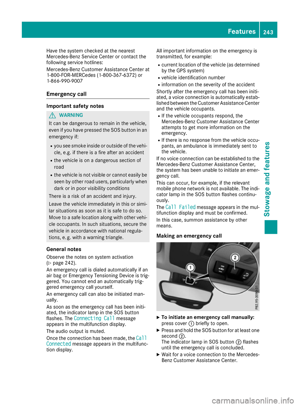
XTo initiate an emergency call manually:
press cover :briefly to open.
XPress and hold the SOS button for at least one
second ;.
The indicator lamp in SOS button ;flashes
until the emergency call is concluded.
XWait for a voice connection to the Mercedes-
Benz Customer Assistance Center.
Features243
Stowag ean d features
Z
Page 246 of 318
XTo end a call:press the~button on the
multifunction steering wheel.
or
XPress the corresponding multimedia system
button for ending a phone call.
XAfter the emergency call, close cover :.
If the mobile phone network is unavailable,
mbrace will not be able to make the emergency
call. If you leave the vehicle immediately after
pressing SOS button ;, you do not know if
mbrace has successfully made the emergency
call. In this case, always summon assistance by
other means.
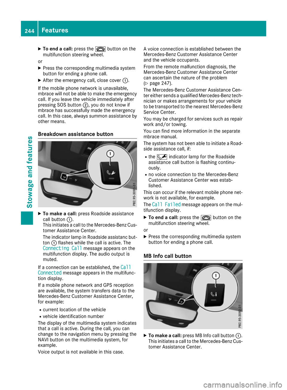
Breakdown assistance button
XTo make a call: press Roadside assistance
call button :.
This initiates a call to the Mercedes-Benz Cus-
tomer Assistance Center.
The indicator lamp in Roadside assistanc but-
ton :flashes while the call is active. The
Connecting Call
message appears on the
multifunction display. The audio output is
muted.
If a connection can be established, the Call
Connectedmessage appears in the multifunc-
tion display.
If a mobile phone network and GPS reception
are available, the system transfers data to the
Mercedes-Benz Customer Assistance Center,
for example:
Rcurrent location of the vehicle
Rvehicle identification number
The display of the multimedia system indicates
that a call is active. During the call, you can
change to the navigation menu by pressing the
NAVI button on the multimedia system, for
example.
Voice output is not available in this case. A voice connection is established between the
Mercedes-Benz Customer Assistance Center
and the vehicle occupants.
From the remote malfunction diagnosis, the
Mercedes-Benz Customer Assistance Center
can ascertain the nature of the problem
(
Ypage 247).
The Mercedes-Benz Customer Assistance Cen-
ter either sends a qualified Mercedes-Benz tech-
nician or makes arrangements for your vehicle
to be transported to the nearest Mercedes-Benz
Service Center.
You may be charged for services such as repair
work and/or towing.
You can find more information in the separate
mbrace manual.
The system has not been able to initiate a Road-
side assistance call, if:
Rthe F indicator lamp for the Roadside
assistance call button is flashing continu-
o
usly.
Rno voice connection to the Mercedes-Benz
Customer Assistance Center was estab-
lished.
This can occur if the relevant mobile phone net- work is not available, for example.
The Call
Failedmessage appears on the mul-
tifunction display.
XTo end a call: press the~button on the
multifunction steering wheel.
or
XPress the corresponding multimedia system
button for ending a phone call.
MB Info call button
XTo make a call: press MB Info call button :.
This initiates a call to the Mercedes-Benz Cus-
tomer Assistance Center.
244Features
Stowag ean d features
Page 247 of 318
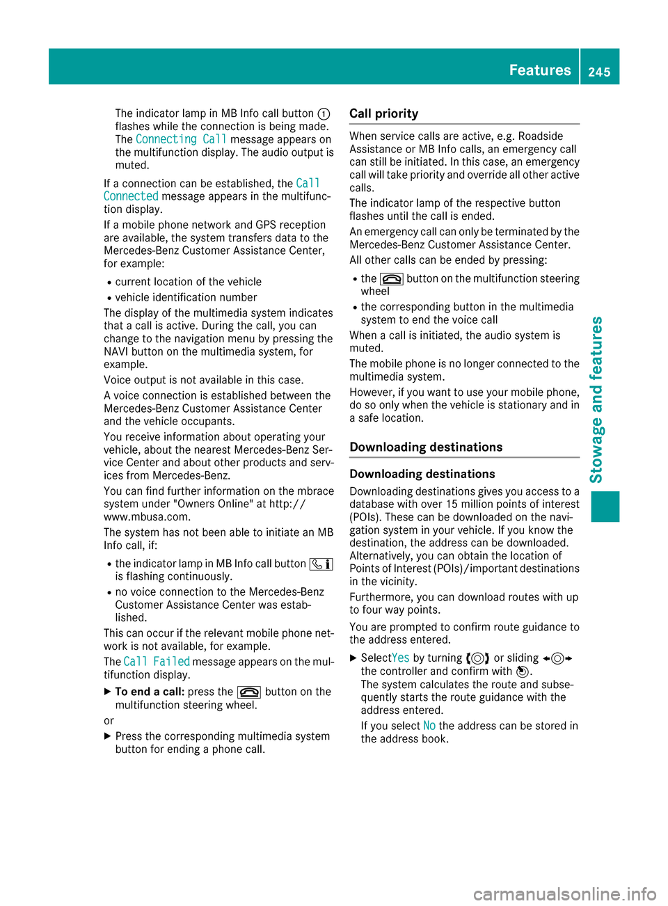
The indicator lamp in MB Info call button:
flashes while the connection is being made.
The Connecting Call
message appears on
the multifunction display. The audio output is
muted.
If a connection can be established, the Call
Connectedmessage appears in the multifunc-
tion display.
If a mobile phone network and GPS reception
are available, the system transfers data to the
Mercedes-Benz Customer Assistance Center,
for example:
Rcurrent location of the vehicle
Rvehicle identification number
The display of the multimedia system indicates
that a call is active. During the call, you can
change to the navigation menu by pressing the
NAVI button on the multimedia system, for
example.
Voice output is not available in this case.
A voice connection is established between the
Mercedes-Benz Customer Assistance Center
and the vehicle occupants.
You receive information about operating your
vehicle, about the nearest Mercedes-Benz Ser-
vice Center and about other products and serv-
ices from Mercedes-Benz.
You can find further information on the mbrace
system under "Owners Online" at http://
www.mbusa.com.
The system has not been able to initiate an MB
Info call, if:
Rthe indicator lamp in MB Info call button ï
is flashing continuously.
Rno voice connection to the Mercedes-Benz
Customer Assistance Center was estab-
lished.
This can occur if the relevant mobile phone net-
work is not available, for example.
The Call
Failedmessage appears on the mul-
tifunction display.
XTo end a call: press the~button on the
multifunction steering wheel.
or
XPress the corresponding multimedia system
button for ending a phone call.
Call priority
When service calls are active, e.g. Roadside
Assistance or MB Info calls, an emergency call
can still be initiated. In this case, an emergency
call will take priority and override all other active
calls.
The indicator lamp of the respective button
flashes until the call is ended.
An emergency call can only be terminated by the
Mercedes-Benz Customer Assistance Center.
All other calls can be ended by pressing:
Rthe ~ button on the multifunction steering
wheel
Rthe corresponding button in the multimedia
system to end the voice call
When a call is initiated, the audio system is
muted.
The mobile phone is no longer connected to the
multimedia system.
However, if you want to use your mobile phone,
do so only when the vehicle is stationary and in
a safe location.
Downloading destinations
Downloading destinations
Downloading destinations gives you access to a
database with over 15 million points of interest
(POIs). These can be downloaded on the navi-
gation system in your vehicle. If you know the
destination, the address can be downloaded.
Alternatively, you can obtain the location of
Points of Interest (POIs)/important destinations
in the vicinity.
Furthermore, you can download routes with up
to four way points.
You are prompted to confirm route guidance to
the address entered.
XSelect Yesby turning 3or sliding 1
the controller and confirm with 7.
The system calculates the route and subse-
quently starts the route guidance with the
address entered.
If you select No
the address can be stored in
the address book.
Features245
Stowage and features
Z
Page 274 of 318
the household rubbish. They
must be collected separatelyand recycled to protect the
environment.
Dispose of batteries in an
environmentally friendly
manner. Take discharged
batteries to a qualified spe-
cialist workshop or a special
collection point for used bat-
teries.
!Have the battery checked regularly at a
qualified specialist workshop.
Observe the service intervals in the Mainte-
nance Booklet or contact a qualified specialist
workshop for more information.
!You should have all work involving the bat-
tery carried out at a qualified specialist work-
shop. In the exceptional case that it is neces-
sary for you to disconnect the battery your-
self, make sure that:
Ryou switch off the engine and remove the
key. On vehicles with KEYLESS-GO, ensure
that the ignition is switched off. Check that
all the indicator lamps in the instrument
cluster are off. Otherwise, electronic com-
ponents, such as the alternator, may be
damaged.
Ryou first remove the negative terminal
clamp and then the positive terminal
clamp. Never swap the terminal clamps.
Otherwise, the vehicle's electronic system
may be damaged.
Rin vehicles with automatic transmission,
the transmission is locked in position P
after disconnecting the battery. The vehicle
is s
ecured against rolling away. You can
then no longer move the vehicle.
The battery and the cover of the positive ter-
minal clamp must be installed securely during
operation.
Comply with safety precautions and take pro-
tective measures when handling batteries.
Risk of explosion.
Fire, open flames and smoking are
prohibited when handling the bat-
tery. Avoid creating sparks.
Battery acid is caustic. Avoid contact
with skin, eyes or clothing.
Wear suitable protective clothing,
especially gloves, apron and face-
guard.
Rinse any acid spills immediately
with clear water. Contact a physician
if necessary.
Wear eye protection.
Keep children away.
Observe this Operator's Manual.
For safety reasons, Mercedes-Benz recom-
mends that you only use batteries which have
been tested and approved for your vehicle by
Mercedes-Benz. These batteries provide
increased impact protection to prevent vehicle
occupants from suffering acid burns should the
battery be damaged in the event of an accident.
In order for the battery to achieve the maximum
possible service life, it must always be suffi-
ciently charged.
Like other batteries, the vehicle battery may
discharge over time if you do not use the vehicle.
In this case, have the battery disconnected at a
qualified specialist workshop. You can also
charge the battery with a charger recommended
by Mercedes-Benz. Contact a qualified special-
ist workshop for further information.
Have the battery condition of charge checked
more frequently if you use the vehicle mainly for
short trips or if you leave it standing idle for a
lengthy period. Consult a qualified specialist
workshop if you wish to leave your vehicle
parked for a long period of time.
Only replace a battery with a battery that has
been recommended by Mercedes-Be nz.
272Battery (vehicle)
Breakdown assistance