bonnet MERCEDES-BENZ CLA COUPE 2016 Owners Manual
[x] Cancel search | Manufacturer: MERCEDES-BENZ, Model Year: 2016, Model line: CLA COUPE, Model: MERCEDES-BENZ CLA COUPE 2016Pages: 345, PDF Size: 12.41 MB
Page 9 of 345
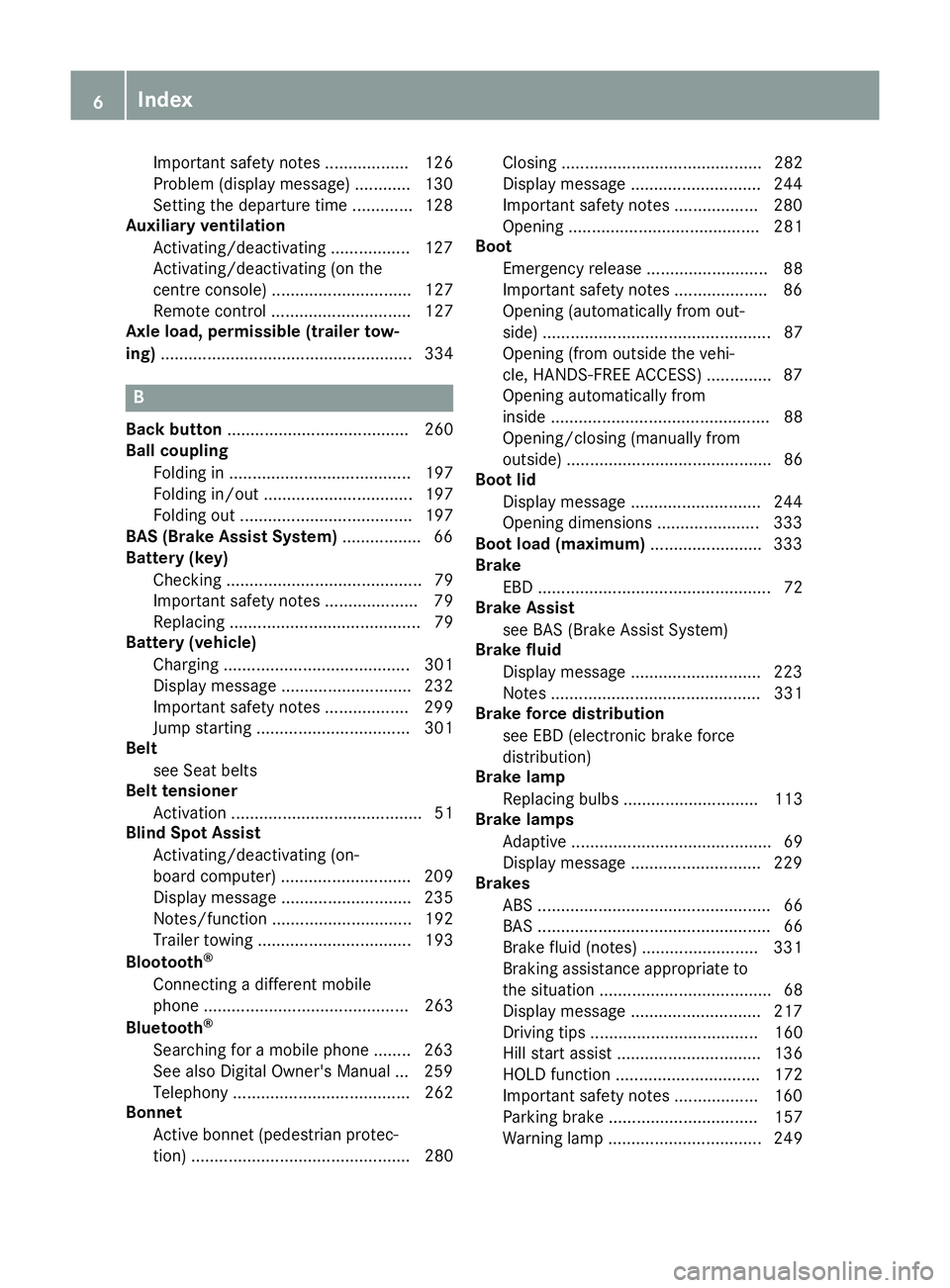
Important safety notes .................. 126
Problem (display message) ............ 130
Setting the departure time .............1
28
Auxiliary ventilation
Activating/deactivating ................. 127
Activating/deactivating (on the
centre console ).............................. 127
Remote control .............................. 127
Axle load, permissible (trailer tow-
ing) ...................................................... 334 B
Back button ....................................... 260
Ball coupling
Folding in ....................................... 197
Folding in/out ................................ 197
Folding out ..................................... 197
BAS (Brake Assist System) ................. 66
Battery (key)
Checking .......................................... 79
Important safety notes .................... 79
Replacing ......................................... 79
Battery (vehicle)
Charging ........................................ 301
Display message ............................ 232
Important safety notes .................. 299
Jump starting ................................. 301
Belt
see Seat belts
Belt tensioner
Activation ......................................... 51
Blind Spot Assist
Activating/deactivating (on-
board computer) ............................ 209
Display message ............................ 235
Notes/function .............................. 192
Trailer towing ................................. 193
Blootooth ®
Connecting a different mobile
phone ............................................ 263
Bluetooth ®
Searching for a mobile phone ........ 263
See also Digital Owner's Manua l... 259
Telephony ...................................... 262
Bonnet
Active bonnet (pedestrian protec-tion) ............................................... 280 Closing ........................................... 282
Display message ............................ 244
Important safety notes .................. 280
Opening ......................................... 281
Boot
Emergency release .......................... 88
Important safety notes .................... 86
Opening (automatically from out-
side) ................................................. 87
Opening (from outside the vehi-
cle, HANDS-FREE ACCESS) .............. 87
Opening automatically from
inside ............................................... 88
Opening/closing (manually from
outside) ............................................ 86
Boot lid
Display message ............................ 244
Opening dimensions ...................... 333
Boot load (maximum) ........................ 333
Brake
EBD .................................................. 72
Brake Assist
see BAS (Brake Assist System)
Brake fluid
Display message ............................ 223
Notes ............................................. 331
Brake force distribution
see EBD (electronic brake force
distribution)
Brake lamp
Replacing bulb s............................. 113
Brake lamps
Adaptive ........................................... 69
Display message ............................ 229
Brakes
ABS .................................................. 66
BAS .................................................. 66
Brake fluid (notes) ......................... 331
Braking assistance appropriate to
the situation ..................................... 68
Display message ............................ 217
Driving tip s.................................... 160
Hill start assist ............................... 136
HOLD function ............................... 172
Important safety notes .................. 160
Parking brake ................................ 157
Warning lamp ................................. 249 6
Index
Page 33 of 345
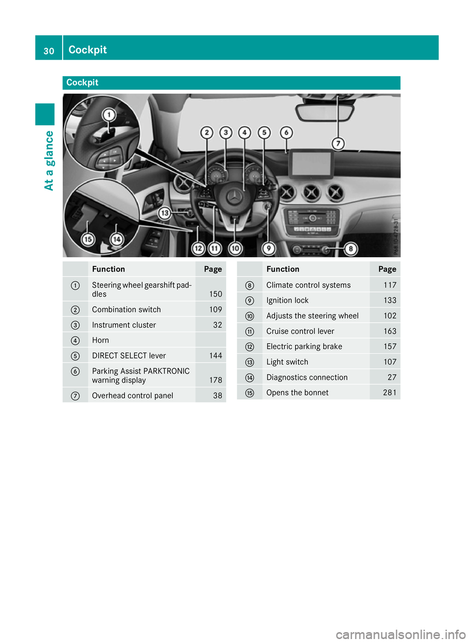
Cockpit
Function Page
:
Steering wheel gearshift pad-
dles 150
;
Combination switch 109
=
Instrument cluster 32
?
Horn
A
DIRECT SELECT lever 144
B
Parking Assist PARKTRONIC
warning display
178
C
Overhead control panel 38 Function Page
D
Climate control systems 117
E
Ignition lock 133
F
Adjusts the steering wheel 102
G
Cruise control lever 163
H
Electric parking brake 157
I
Light switch 107
J
Diagnostics connection 27
K
Opens the bonnet 28130
CockpitAt a glance
Page 34 of 345
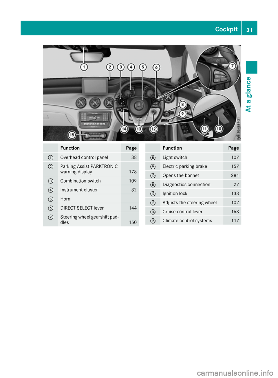
Function Page
:
Overhead control panel 38
;
Parking Assist PARKTRONIC
warning display
178
=
Combination switch 109
?
Instrument cluster 32
A
Horn
B
DIRECT SELECT lever 144
C
Steering wheel gearshift pad-
dles 150 Function Page
D
Light switch 107
E
Electric parking brake 157
F
Opens the bonnet 281
G
Diagnostics connection 27
H
Ignition lock 133
I
Adjusts the steering wheel 102
J
Cruise control lever 163
K
Climate control systems 117Cockpit
31At a glance
Page 76 of 345
Important safety notes
i
Read the "Important safety notes" section
(Y page 66). G
WARNING
If EBD is malfunctioning, the rear wheels can
lock, e.g. under full braking. This increases the risk of skidding and an accident.
You should therefore adapt your driving style
to the different handling characteristics. Have the brake system checked at a qualified spe-
cialist workshop.
Observe information regarding indicator and
warning lamps (Y page 250) as well as display
messages (Y page 219). ADAPTIVE BRAKE
ADAPTIVE BRAKE enhances braking safety and
offers increased braking comfort. In addition to
the braking function, ADAPTIVE BRAKE also has the HOLD function (Y page 172) and hill start
assist (Y page 136). STEER CONTROL
General information STEER CONTROL helps you by transmitting a
noticeable steering force to the steering wheel
in the direction required for vehicle stabilisation.
This steering support is provided in particular if:
R both right wheels or both left wheels are on a
wet or slippery road surface when you brake
R the vehicle begins to skid
Important safety notes i
Read the "Important safety notes" section
(Y page 66).
No steering support is provided from STEER
CONTROL, if: R ESP ®
is malfunctioning
R the steering is malfunctioning
If ESP ®
is malfunctioning, you will be assisted
further by the electrical power steering. Protection against theft
Immobiliser
The immobiliser prevents your vehicle from
being started without the correct key.
X To activate with the key: remove the key
from the ignition lock.
X To activate with KEYLESS-GO start func-
tion or KEYLESS-GO:
switch the ignition off
and open the driver's door.
X To deactivate: switch on the ignition.
When leaving the vehicle, always take the key
with you and lock the vehicle. Anyone can start
the engine if a valid key has been left inside the
vehicle.
i The immobiliser is always deactivated when
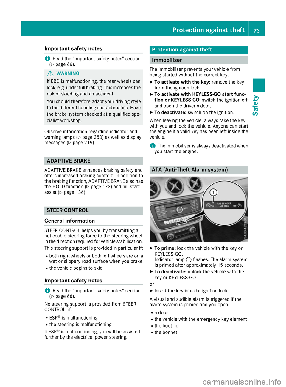
you start the engine. ATA (Anti-Theft Alarm system)
X
To prime: lock the vehicle with the key or
KEYLESS-GO.
Indicator lamp :flashes. The alarm system
is primed after approximately 15 seconds.
X To deactivate: unlock the vehicle with the
key or KEYLESS-GO.
or X Insert the key into the ignition lock.
A visual and audible alarm is triggered if the
alarm system is primed and you open: R a door
R the vehicle with the emergency key element
R the boot lid
R the bonnet Protection against theft
73Safety Z
Page 116 of 345
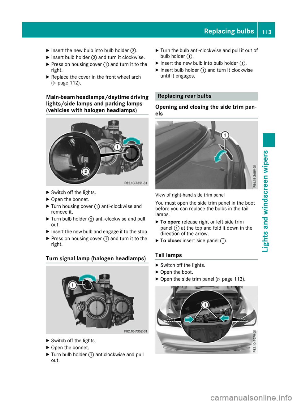
X
Insert the new bulb into bulb holder ;.
X Insert bulb holder ;and turn it clockwise.
X Press on housing cover :and turn it to the
right.
X Replace the cover in the front wheel arch
(Y page 112).
Main-beam headlamps/daytime driving
lights/side lamps and parking lamps
(vehicles with halogen headlamps) X
Switch off the lights.
X Open the bonnet.
X Turn housing cover :anti-clockwise and
remove it.
X Turn bulb holder ;anti-clockwise and pull
out.
X Insert the new bulb and engage it to the stop.
X Press on housing cover :and turn it to the
right.
Turn signal lamp (halogen headlamps) X
Switch off the lights.
X Open the bonnet.
X Turn bulb holder :anticlockwise and pull
out. X
Turn the bulb anti-clockwise and pull it out of
bulb holder :.
X Insert the new bulb into bulb holder :.
X Insert bulb holder :and turn it clockwise
until it engages. Replacing rear bulbs
Opening and closing the side trim pan-
els View of right-hand side trim panel
You must open the side trim panel in the boot
before you can replace the bulbs in the tail
lamps.
X To open: release right or left side trim
panel :at the top and fold it down in the
direction of the arrow.
X To close: insert side panel :.
Tail lamps X
Switch off the lights.
X Open the boot.
X Open the side trim panel (Y page 113). Replacing bulbs
113Lights and windscreen wipers Z
Page 118 of 345
Replacing the wiper blades
Important safety notes G
WARNING
If the windscreen wipers begin to move while
you are changing the wiper blades, you can be trapped by the wiper arm. There is a risk of
injury.
Always switch off the windscreen wipers and
ignition before changing the wiper blades.
! To avoid damaging the windscreen wiper
blades, make sure that you touch only the
wiper arm of the windscreen wiper.
! Never open the bonnet if a windscreen
wiper arm has been folded away from the
windscreen.
Never fold a windscreen wiper arm without a
wiper blade back onto the windscreen.
Hold the windscreen wiper arm firmly when
you change the wiper blade. If you release the
windscreen wiper arm without a wiper blade
and it falls onto the windscreen, the wind-
screen may be damaged by the force of the
impact.
Mercedes-Benz recommends that you have
the wiper blades changed at a qualified spe-
cialist workshop.
Replacing the windscreen wiper blades Removing the wiper blades
X Vehicles without KEYLESS-GO or KEY-
LESS-GO start function:
remove the key
from the ignition lock.
X Vehicles with KEYLESS-GO or KEYLESS-
GO start function:
switch off the engine.
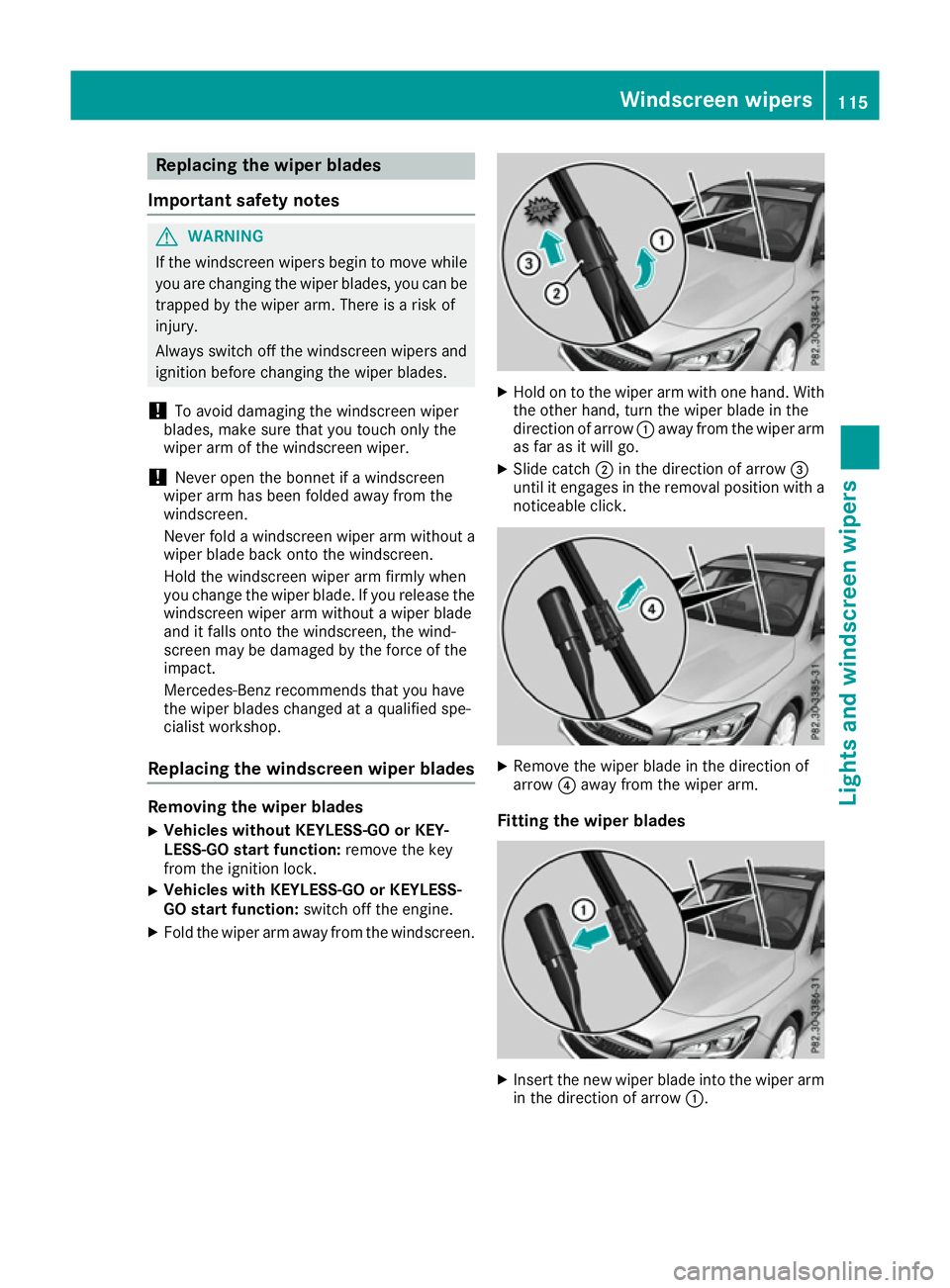
X Fold the wiper arm away from the windscreen. X
Hold on to the wiper arm with one hand. With
the other hand, turn the wiper blade in the
direction of arrow :away from the wiper arm
as far as it will go.
X Slide catch ;in the direction of arrow =
until it engages in the removal position with a noticeable click. X
Remove the wiper blade in the direction of
arrow ?away from the wiper arm.
Fitting the wiper blades X
Insert the new wiper blade into the wiper arm
in the direction of arrow :. Windscreen wipers
115Lights and windscreen wipers Z
Page 133 of 345
Problems with the auxiliary heating/ventilation
Problem
Possible causes/consequences and
M
MSolutions FAIL¨ The signal transmission between the transmitter and the vehicle is
faulty.
X
Change your position in relation to the vehicle, moving closer if
necessary.
X Make another attempt to switch the auxiliary heating/ventilation on
or off using the remote control. FAIL The auxiliary heating cannot be switched on or has switched itself off.
The starter battery is not sufficiently charged.
X Charge the starter battery.
X Make another attempt to switch on the auxiliary heating/ventilation
using the remote control. The auxiliary heating cannot be switched on or has switched itself off.
The fuel tank content is below the reserve fuel level.
X Refuel at the nearest filling station.
X Make another attempt to switch on the auxiliary heating using the
remote control. The auxiliary heating/ventilation cannot be switched on or has
switched itself off.
The auxiliary heating/ventilation is malfunctioning.
X Have the auxiliary heating/ventilation checked at a qualified spe-
cialist workshop. Air vents
Important safety notes
G
WARNING
Very hot or very cold air can flow from the air vents. This could result in burns or frostbite in the immediate vicinity of the air vents. There
is a risk of injury.
Make sure that all vehicle occupants always
maintain a sufficient distance to the air out-
lets. If necessary, redirect the airflow to
another area of the vehicle interior. In order to ensure the direct flow of fresh air
through the air vents into the vehicle interior,
please observe the following notes:
R keep the air inlet between the windscreen and
the bonnet free of blockages, such as ice,
snow or leaves
R never cover the vents or ventilation grilles in
the vehicle interior
i Optimal climate control function is achieved
by opening the air vents fully and setting the
adjusters to the middle position. 130
Air ventsClimate control
Page 140 of 345
Hill start assist is not active if:
R you are pulling away on a level road or a
downhill gradient
R on vehicles with automatic transmission, the
transmission is in position N
R the electric parking brake is applied
R ESP ®
is malfunctioning
Further information on holding the vehicle sta-
tionary on uphill gradients (Y page 148).ECO start/stop function
Introduction The ECO start/stop function switches the
engine off automatically if the vehicle is stopped
under certain conditions.
When pulling away again, the engine starts auto-
matically. The ECO start/stop function thereby
helps you to reduce the fuel consumption and
emissions of your vehicle.
Important safety notes G
WARNING
If the engine is switched off automatically and you exit the vehicle, the engine is restarted
automatically. The vehicle may begin moving. There is a risk of accident and injury.
If you wish to exit the vehicle, always turn off
the ignition and secure the vehicle against
rolling away.
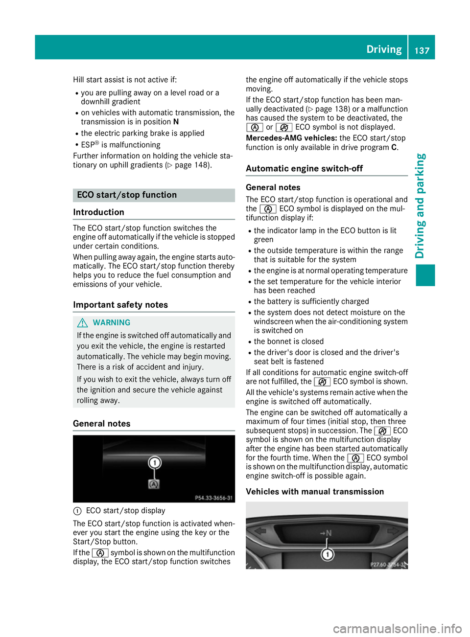
General notes :
ECO start/stop display
The ECO start/stop function is activated when-
ever you start the engine using the key or the
Start/Stop button.
If the è symbol is shown on the multifunction
display, the ECO start/stop function switches the engine off automatically if the vehicle stops
moving.
If the ECO start/stop function has been man-
ually deactivated (Y page 138) or a malfunction
has caused the system to be deactivated, the
è orç ECO symbol is not displayed.
Mercedes-AMG vehicles: the ECO start/stop
function is only available in drive program C.
Automatic engine switch-off General notes
The ECO start/stop function is operational and
the è ECO symbol is displayed on the mul-
tifunction display if:
R the indicator lamp in the ECO button is lit
green
R the outside temperature is within the range
that is suitable for the system
R the engine is at normal operating temperature
R the set temperature for the vehicle interior
has been reached
R the battery is sufficiently charged
R the system does not detect moisture on the
windscreen when the air-conditioning system
is switched on
R the bonnet is closed
R the driver's door is closed and the driver's
seat belt is fastened
If all conditions for automatic engine switch-off
are not fulfilled, the çECO symbol is shown.
All the vehicle's systems remain active when the engine is switched off automatically.
The engine can be switched off automatically a
maximum of four times (initial stop, then three
subsequent stops) in succession. The çECO
symbol is shown on the multifunction display
after the engine has been started automatically
for the fourth time. When the èECO symbol
is shown on the multifunction display, automatic
engine switch-off is possible again.
Vehicles with manual transmission Driving
137Driving and parking Z
Page 178 of 345
is an increased risk of skidding and having an
accident. Make sure that no persons, animals
or obstacles are within range of the vehicle.
RACE START enables optimum acceleration
from a standing start. For this, a suitably high-
grip road surface is required; the tyres and vehi-
cle must also be in good condition.
i Observe the safety notes on driving safety
systems (Y page 66).
Be sure to read the safety notes and informa-
tion on ESP ®
(Y page 69).
Activation conditions You can activate RACE START if:
R the doors, the bonnet and the boot lid are
closed
R the engine is running and the transmission,
traction control and engine are at operating
temperature
R the steering wheel is in the straight-ahead
position
R the vehicle is stationary and the brake pedal is
depressed (left foot)
R the transmission is in position D
R one of the drive programs S,S+ orRACE is
selected (Y page 141)
Activating RACE START X
Depress the brake pedal with your left foot
and keep it depressed.
X Pull and hold both steering wheel gearshift
paddles.
X The RACE START Confirm: Paddle UP RACE START Confirm: Paddle UP
Cancel: Paddle DOWN
Cancel: Paddle DOWN message appears in
the multifunction display.
X Release both steering wheel gearshift pad-
dles.
i If the activation conditions are no longer ful-
filled, RACE START is cancelled. The RACE
RACE
START not possible See Owner's Man‐
START not possible See Owner's Man‐
ual
ual message appears in the multifunction
display. X
To cancel: pull the left steering wheel shift
paddle (Y page 150).
or X To confirm: pull the right steering wheel shift
paddle (Y page 150).
The RACE START available Depress
RACE START available Depress
accelerator
accelerator message appears in the multi-
function display.
i If you do not depress the accelerator pedal
within a few seconds, RACE START is cancel-
led. The multifunction display shows the
RACE START cancelled RACE START cancelled message.
X Fully depress the accelerator pedal.
The engine speed increases.
The RACE RACE START
START Release
Release brake
braketo
tostart
start
message appears in the multifunction display.
i If the brake pedal is not released after a
short while, RACE START is cancelled. The
multifunction display shows the RACE RACESTART
START
cancelled
cancelled message.
X Take your foot off the brake, but keep the
accelerator pedal depressed.
The vehicle pulls away at maximum acceler-
ation.
The RACE RACE START
START active
active message appears in
the multifunction display.
RACE START is deactivated when the vehicle
reaches a speed of approximately 50 km/h.
RACE START is deactivated immediately if you
release the accelerator pedal during RACE
START or if any of the activation conditions are
no longer fulfilled. The RACE START not pos‐
RACE START not pos‐
sible sible orRACE START cancelled
RACE START cancelled message
appears in the multifunction display.
i After using it several times in short succes-
sion, RACE START will be unavailable until a
certain distance has been driven. AMG RIDE CONTROL
General notes The electronically controlled damping system
works continuously. This improves driving
safety and ride comfort. Driving systems
175Driving and parking Z
Page 204 of 345
There is a short delay before a change in outside
temperature appears in the multifunction dis-
play. Coolant temperature gauge
G
WARNING
If you open the bonnet while the engine is
overheating or while there is a fire in the
engine compartment, you could come into
contact with hot gases or other leaking ser-
vice products. There is a danger of injury.
Allow an overheating engine to cool down
before opening the bonnet. If there is a fire in the engine compartment, leave the bonnet
closed and notify the fire brigade.
The coolant temperature gauge is in the instru-
ment cluster on the right-hand side (Y page 32).
Under normal operating conditions and with the correct coolant level, the coolant temperature
may rise to 120 †.
At high outside temperatures and when driving
in mountainous terrain, the coolant temperature may rise to the end of the scale. Operating the on-board computer
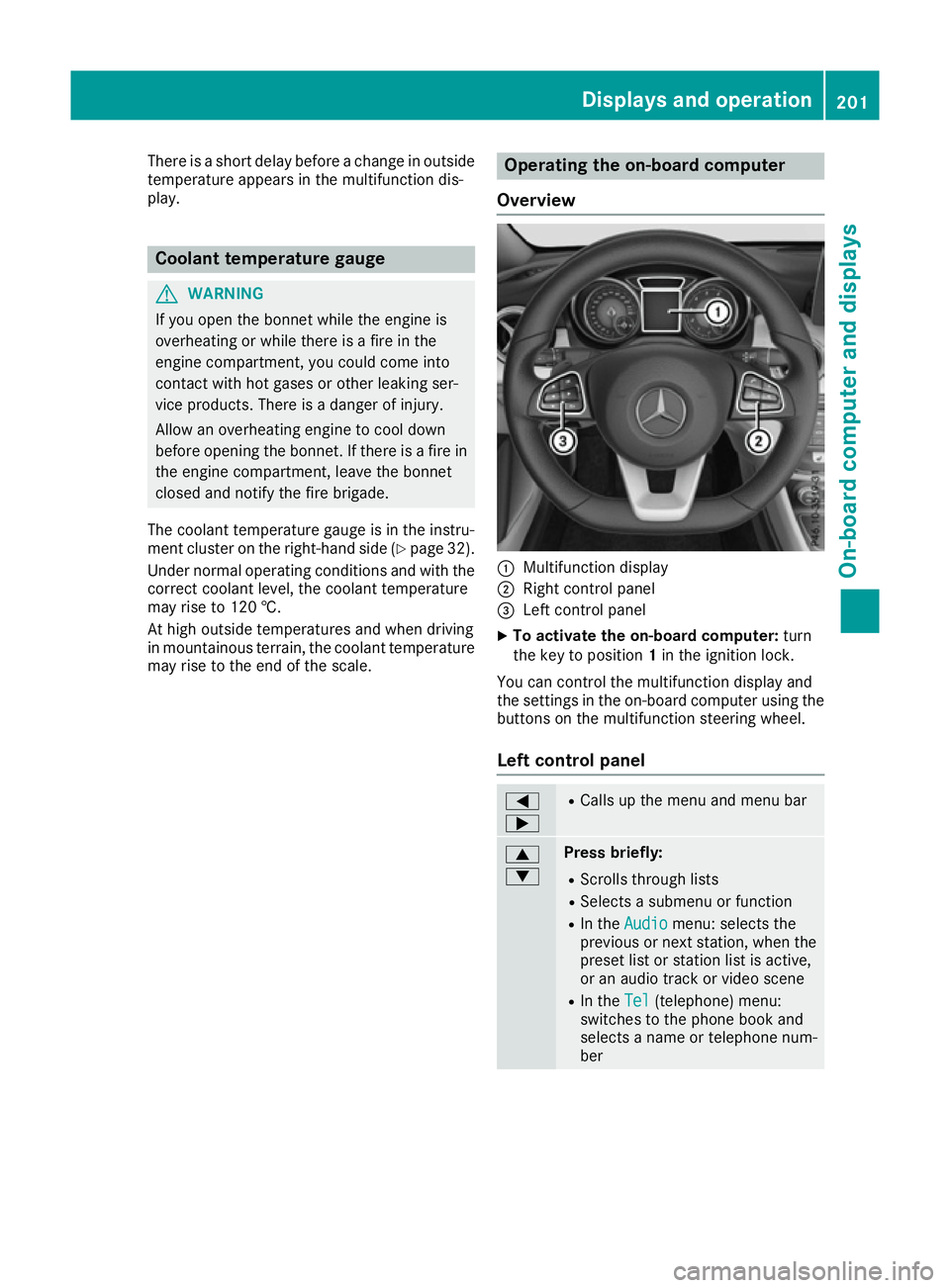
Overview :
Multifunction display
; Right control panel
= Left control panel
X To activate the on-board computer: turn
the key to position 1in the ignition lock.
You can control the multifunction display and
the settings in the on-board computer using the buttons on the multifunction steering wheel.
Left control panel =
; R
Calls up the menu and menu bar 9
: Press briefly:
R Scrolls through lists
R Selects a submenu or function
R In the Audio Audio menu: selects the
previous or next station, when the preset list or station list is active,
or an audio track or video scene
R In the Tel Tel(telephone) menu:
switches to the phone book and
selects a name or telephone num-
ber Displays and operation
201On-board computer and displays Z