MERCEDES-BENZ CLA COUPE 2019 Owner's Manual
Manufacturer: MERCEDES-BENZ, Model Year: 2019, Model line: CLA COUPE, Model: MERCEDES-BENZ CLA COUPE 2019Pages: 330, PDF Size: 52.4 MB
Page 311 of 330
Uniform
TireQualit yGra ding Standar ds
A unifor mstan dard tograde thequality oftires
with regards totread quality, tiretraction and
tempe rature charac teristics.The quality grad-
ing assessmen tis made bythe manufac turer
following specificationsfrom theU.S.govern -
ment .The ratin gsare molded intothe sidewall of
the tire.
Recomm endedtirepr essures
The recom mended tirepressure appliestothe
tires mount edatthe factory.
The Tire andLoading Informat ionplacard con-
tains therecom mended tirepressures forcold
tires onafully loaded vehicle andforthe maxi-
mum permissible vehiclespeed.
The tirepressure tablecontains therecom men-
ded pressures forcold tires forvarious operat-
ing con dition s,i.e. differin gload andspeed con-
dition s.
Increased vehicleweightduetooptiona l
equip ment
The combin edweight ofall stan dard and
option alequipment availableforthe vehicle,
regardless ofwhether itis actually installed on
the vehicle ornot .
Rim
This isthe part ofthe wheel onwhich thetire is
mount ed.
GAWR (Gross AxleWeight Rating)
The GAWR isthe maximum grossaxleweight
ratin g.The actual loadonanaxle must never
exc eed thegross axleweight rating.The gross
axle weight ratingcan befound onthe vehicle
ident ificationplate onthe B-pillar onthe driver' s
side.
Speed rating
The speed ratingis part ofthe tire ident ification.
It specifies thespeed rangeforwhich thetire is
approved.
GVW (Gross Vehicle Weight)
The gross vehicle weightincludes theweight of
the vehicle includin gfuel, tools, thespare wheel,
access oriesinstalled, occupants, luggage and
the drawbar noseweight ,if applicable. Thegross
vehicle weightmustnotexceed thegross vehi-
cle weight ratingGVWR asspecified onthe vehi-
cle ident ificationplate onthe B-pillar onthe
driver' sside. GVW
R(Gross Vehicle WeightRating)
The GVWR isthe maximum permissible gross
weight ofafully loaded vehicle (theweight ofthe
vehicle includin gall acces sories, occupants,
fuel, luggage andthedrawbar noseweight ,if
applicable). Thegross vehicle weightratingis
specified onthe vehicle identificationplate on
the B-pillar onthe driver' sside.
Maxim umloaded vehicle weight
The maximum weightisthe sum of:
R the curb weight ofthe vehicle
R the weight ofthe acces sories
R the load limit
R the weight ofthe factoryinstalled option al
equipment
Kilopascal (kPa)
Metr icunit fortire pressure. 6.9kPa corre-
sponds to1psi. Another unitfortire pressure is
bar. 100 kilopasc als(kPa) arethe equivalent of
1 bar.
Load index
In addition tothe load-bearin gindex ,the load
index mayalsobeimprin tedonthe sidewall of
the tire. This specifies theload-bearin gcapacit y
more precise ly.
Curb weight
The weight ofavehicle withstandard equipment
includin gthe maximum capacityof fuel, oiland
coolant .It also includes theair-c ondit ioningsys-
tem andoption alequipment ifthese areinstal-
led inthe vehicle, butdoes notinclude passen-
gers orluggage.
Maxim umload rating
The maximum tireload isthe maximum permis-
sible weight inkilogram sor lbs forwhich atire is
approved.
Maxim umperm issible tirepr essure
Maximum permissible tirepressure forone tire.
Maxim umload onone tire
Maximum loadonone tire. This iscalculated by
dividing themaximum axleload ofone axle by
two. All
about wheels andtires
309Wheels andtires Z
Page 312 of 330
PSI
(pounds persquar einch)
A standard unitofmeasure fortire pressure.
Aspect ratio
Relationship betweentireheight andtirewidth
in percent .
Tire pressur e
This ispressure insidethetire apply inganout-
ward force toeach square inchofthe tire's sur-
face. Thetirepressure isspecified inpounds per
square inch(psi), inkilopascal (kPa)orinbar.
The tirepressure shouldonlybecorrect edwhen
the tires arecold.
Cold tirepressur e
The tires arecold:
R ifthe vehicle hasbeen parked withthetires
out ofdirect sunlight foratleast three hours
and
R ifthe vehicle hasnotbeen driven further than
1 mile (1.6km)
Tread
The part ofthe tire that comes intocont actwith
the road.
Bead The tirebead ensures thatthetire sits securely
on the wheel. Thereareseveral steelwires inthe
bead toprevent thetire from coming loosefrom
the wheel rim.
Sidewall The part ofthe tire between thetread andthe
bead.
Weight ofoptional extras
The combined weightofthose optional extras
that weigh morethanthereplaced standard
parts andmore than2.3kg(5lbs). These
optional extras,such ashigh-performanc e
brakes, levelcontrol,aroof rack orahigh-per-
formanc ebattery, arenot included inthe curb
weight andtheweight ofthe accessories.
TIN (Tire Identification Number)
This isaunique identifier whichcanbeused by
a tire manufacturer toidentify tires,forexample
for aproduct recall,andthus identify thepur-
chasers. TheTINismade upofthe manufactur-
er's identity code,tiresize, tiretype code and
the manufacturing date. Load
bearing index
The load bearing index(alsoloadindex) isacode
that contains themaximum loadbearing capa-
city ofatire.
Tra ction
Traction isthe result offrict ionbetween thetires
and theroad surface.
Tread wearindicators
Narrow bars(tread wearbars) thataredistrib-
uted overthetire tread. Ifthe tire tread islevel
with thebars, thewear limitof00CD in(1.6 mm)
has been reached.
Occupant distribution
The distribution ofoccupants inavehicle attheir
designated seatingpositions.
Total loadlimit
Nominal loadandluggage loadplus68kg
(15 0lbs )multiplied bythe number ofseats in
the vehicle. Changing
awheel Flat
tire
The "Breakdown assistance"section
(Y page 274)contains information andnotes on
how todeal with aflat tire. Inform ationondriv-
ing with MOExt ended tiresinthe event ofaflat
tire can befound under "MOExt endedtires(tires
with run-flat characterist ics"(Ypage 275). Rotat
ingthe wheels G
WARNING
Int erchanging thefront andrear wheels may
severely impairthedriving characterist icsif
the wheels ortires have different dimensions.
The wheel brakes orsuspension components
may alsobedamaged. Thereisarisk ofacci-
dent.
Rotate frontandrear wheels onlyifthe wheels
and tires areofthe same dimensions.
! On
vehicles equippedwith atire pressure
monitor ,electron iccomponen tsare located
in the wheel. 310
Changing
awheelWheels andtires
Page 313 of 330
Tire-mount
ingtools should notbeused near
the valve. Thiscould damage theelectron ic
compon ents.
Only have tireschanged ataqualified spe-
cialist workshop.
Observe theinstr uctions andsafety notesinthe
"Changing awheel" section (Ypage 310).
The wear pattern son the front andrear tires
differ, depending onthe operating conditions.
Rotate thewheels beforeaclear wearpattern
has formed onthe tires. Fronttires typically
wear more onthe shoulders andtherear tires in
the cent er.
On vehicles thathave thesame sizefront and
rear wheels, youcan rotat ethe wheels accord-
ing tothe inter valsinthe tire manufact urer's
warranty bookinyour vehicle document s.Ifno
warranty bookisavailabl e,the tires should be
rotat edevery 3,000 to6,000 miles(5,000 to
10,00 0km ).Dependin gon tire wear, thismay
be required earlier.Donot change thedirection
of wheel rotation.
Clean thecont actsurfaces ofthe wheel andthe
brake discthoroughly everytimeawheel isrota-
ted. Check thetire pressure and,ifnecessary,
restart thetire pressure losswarning system
(Canada only)orthe tire pressure monitor(USA
only). Direction
ofrota tion
Tires withaspecified directionofrotat ionhave
additional benefits,e.g. ifthere isarisk ofhydro-
planing. Theseadvantages canonly begained if
the tires areinstalled correspon dingtothe
direction ofrotat ion.
An arrow onthe sidewall ofthe tire indicates its
correc tdirection ofrotat ion. Storing
wheels
Stor ewheels thatarenot being usedinacool,
dry and preferably darkplace. Protectthe tires
from oil,grease, gasoline anddiesel. Mounting
awheel
Prepa ringthevehicle X
Stop thevehicle onsolid, non-slippery and
level ground.
X Apply theelectric parking brakemanually.
X Bring thefront wheels intothestraight- ahead
position.
X Shift thetrans mission toposition 005D.
X Switch offthe engine.
X Vehicles withoutKEYLESS-GO: removethe
Smart Keyfrom theignition lock.
X Vehicles
withKEYL ESS-GO start-function
or KEYL ESS-GO: openthedriver's door.
The vehicle electron icsare now inposition
0092. This isthe same as“key removed”.
X Vehicles
withKEYL ESS-GO start-function
or KEYL ESS-GO: removetheStart /Stopbut-
ton from theignition lock(Ypage 123).
X Make surethattheengine cannotbe start ed
via your smartphon e(Y page 83).
X Ifincluded inthe vehicle equipment, remove
the tire- change toolkitfrom thevehicle.
X Safeguard thevehicle against rollingaway
(Y page 142).
i Apart
fromcertaincount ry-specific varia-
tions, thevehicles arenot equipped witha
tire- change toolkit.Some toolsforchanging a
wheel arespecific tothe vehicle. Formore
inform ationonwhich toolsarerequired to
perform awheel change onyour vehicle, con-
sult aqualified specialist workshop.
Necessary tire-changing toolscaninclude, for
example:
R Jack
R Wheel chock
R Lug wrench Changing
awheel
311Wheels andtires Z
Page 314 of 330
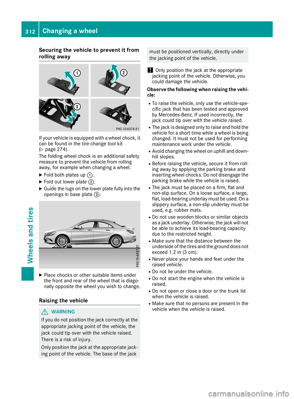
Securing
thevehicle toprevent itfrom
rolling away If
your vehicle isequippe dwith awheel chock,it
can befound inthe tire-c hange toolkit
(Y page 274).
The folding wheelchock isan additional safety
measure toprevent thevehicle fromrolling
away ,for example whenchanging awheel.
X Fold both plates up0043.
X Fold outlower plate0044.
X Guide thelugs onthe lower platefullyintothe
openings inbase plate 0087. X
Place chocksor other suitable itemsunder
the front andrear ofthe wheel thatisdiago-
nally opposite thewheel youwish tochange.
Raising thevehicle G
WARNING
If you donot position thejack correct lyat the
appropriate jackingpoint ofthe vehicle, the
jack could tipover withthevehicle raised.
There isarisk ofinjury.
Only position thejack atthe appropriate jack-
ing point ofthe vehicle. Thebase ofthe jack must
bepositioned vertically,directlyunder
the jackin gpoint ofthe vehicle.
! Only
position thejack atthe appropriate
jackin gpoint ofthe vehicle. Otherwise, you
could damage thevehicle.
Observe thefollow ingwhen raising thevehi-
cle:
R To raise thevehicle, onlyusethevehicle-spe-
cific jack thathasbeen tested andapproved
by Mercedes-B enz.Ifused incorrec tly,the
jack could tipover withthevehicle raised.
R The jack isdesigned onlytoraise andhold the
vehicle forashort timewhile awheel isbeing
changed. Itmust notbeused forperforming
maintenan cework under thevehicle.
R Avoid changing thewheel onuphill anddown-
hill slopes.
R Before raising thevehicle, secureitfrom roll-
ing away byapply ingthe parking brakeand
insertin gwheel chocks.Do not disengage the
parking brakewhilethevehicle israised.
R The jack must beplaced onafirm, flatand
non- slipsurface. Onaloose surface, alarge,
flat, load-bearing underlaymustbeused. Ona
slippery surface, anon- slipunderlay mustbe
used, e.g.rubber mats.
R Do not use wooden blocksorsimilar objects
as ajack underlay. Otherwise, thejack willnot
be able toachieve itsload-bearing capacity
due tothe restrict edheight.
R Make surethatthedistance between the
underside ofthe tires andtheground doesnot
exceed 1.2in(3 cm).
R Never placeyourhands andfeet under the
raised vehicle.
R Do not lieunder thevehicle.
R Do not start theengine whenthevehicle is
raised.
R Do not open orclose adoor orthe trunk lid
when thevehicle israised.
R Make surethatnopersons arepresent inthe
vehicle whenthevehicle israised. 312
Changing
awheelWheels andtires
Page 315 of 330
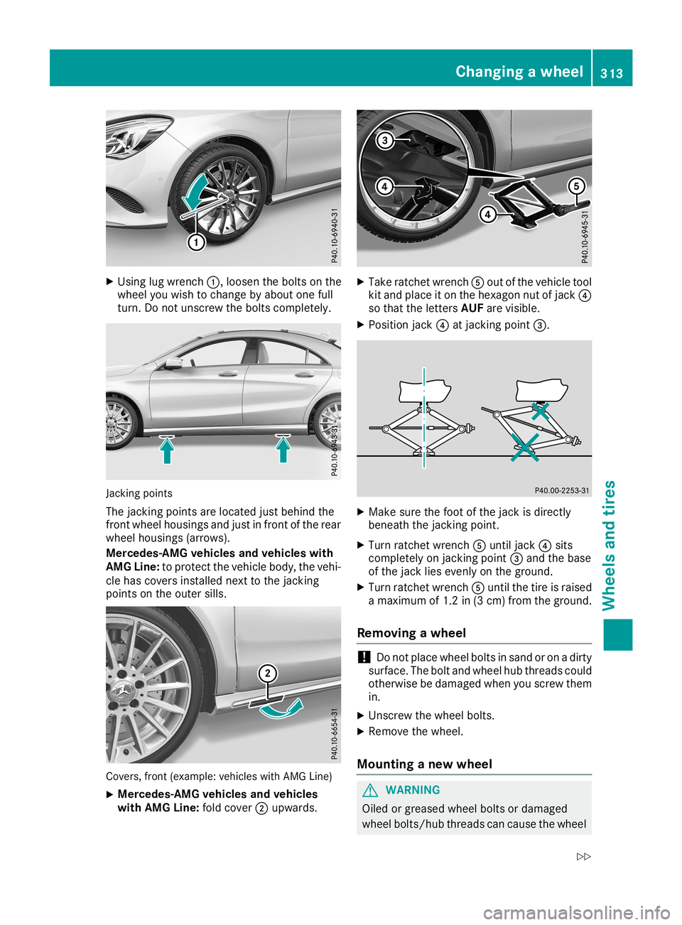
X
Using lugwrench 0043,loosen thebolts onthe
wheel youwish tochange byabou tone full
turn. Donot unscrew thebolts completely. Jacking
points
The jacking pointsarelocated justbehind the
front wheel housings andjust infront ofthe rear
wheel housings (arrows).
Mercedes-AMG vehiclesand vehicl eswith
AMG Line: toprotect thevehicle body,thevehi-
cle has covers installed nexttothe jacking
points onthe outer sills. Covers,
front(example: vehicleswithAMG Line)
X Mercedes-AMG
vehiclesand vehicl es
with AMG Line: foldcover 0044upwa rds. X
Take ratchet wrench 0083out ofthe vehicle tool
kit and place iton the hexagon nutofjack 0085
so that theletters AUFarevisible.
X Position jack0085atjacking point0087. X
Make surethefoot ofthe jack isdirectly
beneath thejacking point.
X Turn ratchet wrench 0083until jack0085sits
completely onjacking point0087and thebase
of the jack liesevenly onthe ground.
X Turn ratchet wrench 0083until thetire israised
a maximum of1.2 in(3 cm )from theground.
Removing awhee l !
Do
not place wheel boltsinsand oron adirty
surface. Thebolt andwheel hubthreads could
otherwise bedamage dwhen youscrew them
in.
X Unscrew thewheel bolts.
X Remove thewheel.
Mounting anew whee l G
WARNING
Oiled orgreased wheelboltsordamage d
wheel bolts/hub threadscancause thewheel Changing
awhee l
313Wheels andtires
Z
Page 316 of 330
bolts
tocome loose. Asaresult, youcould
lose awheel whiledriving .There isarisk of
acciden t.
Never oilorgrease wheelbolts.Inthe event of
damage tothe threads, contact aqualified
specialist workshopimmediately. Havethe
damaged wheelboltsorhub threads
replaced/r enewed.Donot continue driving . G
WARN
ING
If you tight enthe wheel boltsorwheel nuts
when thevehicle israised, thejack could tip
over. There isarisk ofinjury.
Only tightenthe wheel boltsorwheel nuts
when thevehicle ison the ground.
Always payattention tothe instruct ions and
safety notesinthe "Changing awheel" section
(Y page 310).
Only usewheel boltsthathave been designed
for the wheel andthevehicle. Forsafety rea-
sons, Mercedes -Benzrecom mends thatyou
only usewheel boltswhich havebeen approved
for Mercedes -Benzvehicles andtherespect ive
wheel.
! To
preven tdamage tothe paintwor k,hold
the wheel securely againstthewheel hub
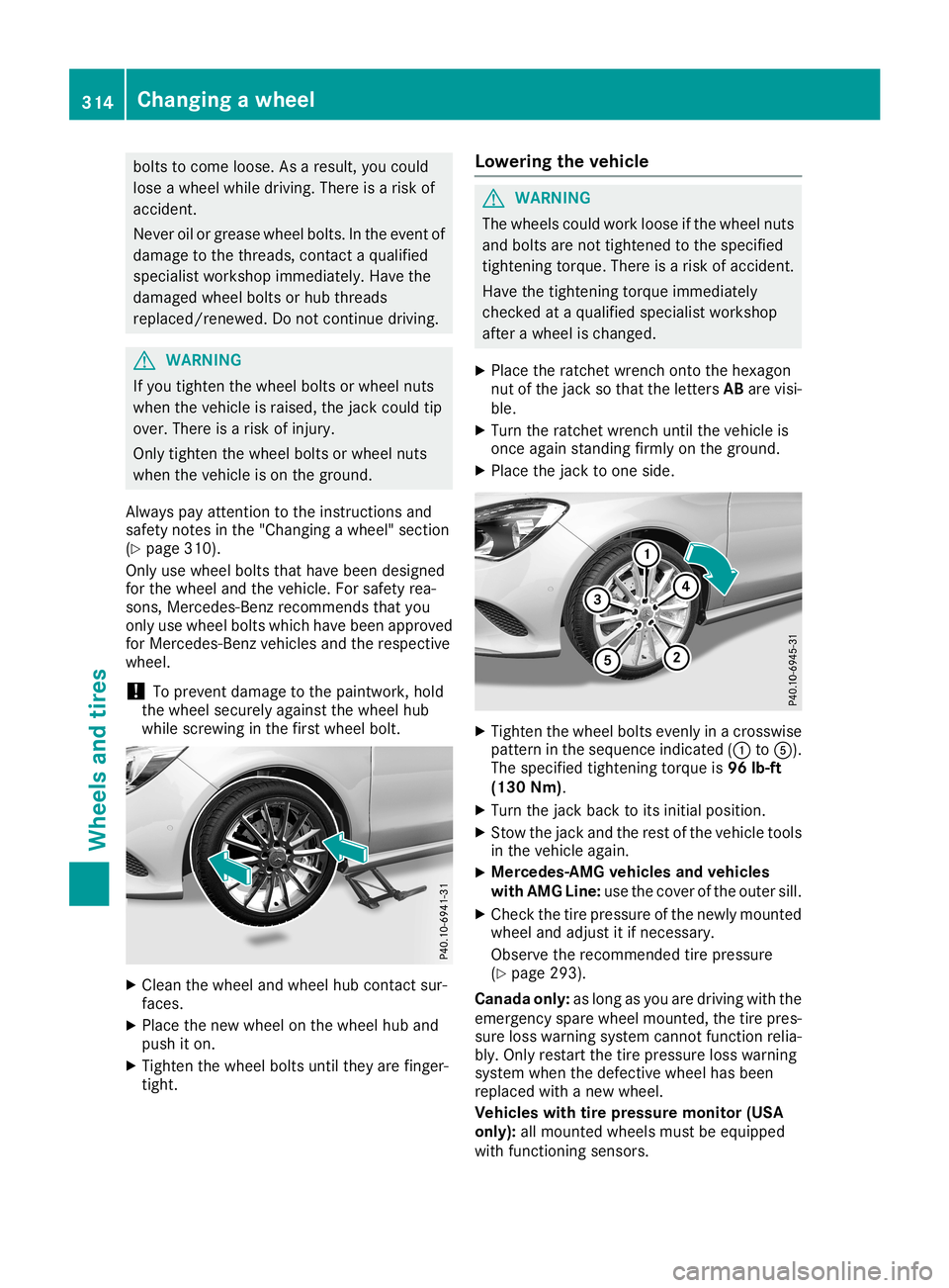
while screwin gin the first wheel bolt. X
Clean thewheel andwheel hubcontact sur-
faces.
X Place thenew wheel onthe wheel huband
push iton.
X Tighten thewheel boltsuntiltheyarefinger -
tight . Lowering
thevehicle G
WARN
ING
The wheels couldworkloose ifthe wheel nuts
and bolts arenot tight ened tothe specified
tight eningtorque. Thereisarisk ofacciden t.
Have thetight eningtorque immediately
chec kedataqualified specialist workshop
after awheel ischang ed.
X Place theratc hetwrenc hont othe hexagon
nut ofthe jack sothat theletters ABare visi-
ble.
X Turn theratc hetwrenc huntil thevehicle is
onc eagain standing firmly onthe ground.
X Place thejack toone side. X
Tighten thewheel boltsevenly inacros swise
patte rninthe sequence indicated(0043 to0083).
The specified tighteningtorque is96 lb-ft
(130 Nm).
X Turn thejack back toits initial position .
X Stow the jack andtherest ofthe vehicle tools
in the vehicle again.
X Mercedes-
AMGvehicles andvehicles
with AMG Line: usethecover ofthe outer sill.
X Check thetire pressure ofthe newly mount ed
wheel andadjust itifnec essary.
Observe therecom mended tirepressure
(Y page 293).
Canad aonly: aslong asyou aredriving withthe
emergen cyspare wheel mounted,the tire pres-
sure losswarning systemcannotfunc tion relia-
bly. Only restartthe tire pressure losswarning
system whenthedefect ivewheel hasbeen
replaced withanew wheel.
Vehicles withtirepr essure monitor (USA
only): allmount edwheels mustbeequipped
with functioningsensor s. 314
Changing
awheelWheels andtires
Page 317 of 330
Whee
land tirecombinatio ns Gene
ralnote s
You canaskforinforma tionrega rding permi tted
whee l/tire combina tionsatan authorized
Merced es-Benz Center.
You shou ldregu larlycheck thepress ureofthe
emerge ncysparewhe el,parti cularlyprio rto
long trips, andcorrect thepress ureasneces-
sary (Ypag e293). Thevalueon the whe elis
vali d.
! For
safe tyreas ons, Merced es-Benz recom-
mends thatyouonly usetires andwheels
whi chhave been approved byMerced es-Benz
speci ficallyfor you rvehicl e.
These tireshave been speciallyada pted for
use with thecontrol systems,such asABS or
ESP ®
,and aremarked asfoll ows:
R MO =Merced es-Benz Original
R MOE =Merced es-Benz OriginalExtended
(tires featuringrun-fla tchara cteristics)
R MO1 =Merced es-Benz Original(only cer-
tain AMG tires)
Merced es-Benz OriginalExtended tiresmay
only beuse don whe elsthat have been spe-
cifica llyapp roved byMerced es-Benz.
Only usetires, wheelsoraccesso riestested
and approved byMerced es-Benz. Certain
chara cteristics, e.g.handl ing,vehicl enoise
emiss ionsorfuel consump tion,mayother-
wis ebe adve rsely affected .In add ition, when
drivi ngwith aloa d,tire dime nsion variations
coul dcaus ethe tires tocome intocontact
with thebody work andaxle components. This
coul dresu ltin dama getothe tires orthe vehi-
cle.
Merced es-Benz accepts noliabil ity for dam-
age resu lting from theuse oftires, wheelsor
accesso riesother thanthose tested and
app roved.
Informatio non tires, wheelsand approved
combina tionscanbeobtai nedfrom anyquali-
fied speci alist worksho p.
! Retrea
dedtires areneither testednorrec-
ommende dby Merced es-Benz, sinceprevi-
ous dama gecannot alwaysbe detected on
retread edtires. Asaresu lt,Merced es-Benz
cannot guarantee vehiclesafe tyifretread ed
tires aremounted .Do not mount usedtires if
you have noinforma tionabouttheir previous
usa ge. The
recommende dpress uresforvari ous oper-
ating conditio nscan befound:
R on the Tire andLoad ingInformatio npla card
on the B-pill aron the drive r'sside
R in the tire press uretablein the fuel filler flap
Obser vethe notes onrecommende dtire pres-
sure sunder various opera tingconditio ns
(Y pag e293) .
Che cktire press uresregularly,and only when
the tires arecold. Comp lywith themaintenance
recommenda tionsofthe tire manufa cturerin
the vehicl edocu ment wallet.
Notes onthe vehicl eequ ipme nt–alw aysequ ip
the vehicl e:
R with tires ofthe same sizeonagive naxle (left
and right)
R with thesame typeoftire (summer tires,
MOExtended tires,winter tires)
Exception: itis permi ssibleto instal la diffe r-
ent type ormake inthe event ofaflat tire.
Obser vethe "MOExtended tires(tires with
run-fla tchara cteristics" section(Ypag e275) .
Vehi cles equipped with MOExtended tiresare
not equippedwith aTIREFIT kitatthe factory .It
is therefore recommende dthat youadditiona lly
equ ipyou rvehicl ewith aTIREFIT kitifyou mount
tires thatdonot featu rerun-fla tprope rties,e.g.
winter tires.ATIREFIT kitmay beobtai nedfrom
a qua lified speci alist worksho p. Emerge
ncyspare wheel Important
safetynotes G
WARNING
The whe elor tire size aswel las the tire type of
the sparewhe elor emerge ncysparewhe el
and thewhe elto be repl aced maydiffer.
Mou nting anemerge ncysparewhe elmay
severe lyimpa irthe drivi ngchara cteristics.
There isarisk ofan accid ent.
To avoi dhaza rdoussitua tions:
R ada ptyou rdrivi ngstyle accordi nglyand
drive carefu lly.
R never mount morethanonesparewhe elor
emerge ncysparewhe elthat differsinsize.
R only useaspa rewhe elor emerge ncyspare
whe elof adiffe rent sizebriefly. Emerge
ncyspare wheel
315Whee lsand tires
Z
Page 318 of 330
R
do not switch ESP®
off.
R have aspare wheel oremergen cyspare
wheel ofadifferen tsize replaced atthe
nearest qualified specialist workshop.
Observe thatthewheel andtiredimension s
as well asthe tire type must becorr ect.
When usinganemergen cyspare wheel orspare
wheel ofadifferen tsize, youmust notexceed
the vehicle's maximum designspeedof50 mph
(8 0km/ h).
You should regularly checkthe press ureofthe
emerg encyspare wheel, particularly priorto
long trips, and correctthe press ureasnec es-
sary (Ypage 293). Thevalue onthe wheel is
valid.
Sn ow chain smust notbemoun tedonemer-
genc yspare wheels. Genera
lnotes
You canaskforinformat ionregard ingpermit ted
emerg encyspare wheels atan author ized
Merc edes- BenzCent er.
An emerg encyspare wheel mayalsobemoun -
ted against thedirec tionofrot ation .Obser ve
the timerest riction onuse aswell asthe speed
limit ation specif iedonthe emerg encyspare
wheel.
Replace thetires afte rsix years atthe latest ,
regard lessofwear. Thisalso applies tothe
emerg encyspare wheel.
Tir epr essur eloss warn ingsyst em(Canad a
only): aslong asyou aredrivin gwith theemer-
genc yspare wheel mounted,thetirepress ure
loss warnin gsyste mcan not func tion reliably.
Only restartthe tirepress ureloss warnin gsys-
tem when thedefec tivewheel hasbeen
replace dwith anew wheel.
Vehicles withtirepr essur emonit or(USA
only): afteran emerg encyspare wheel hasbeen
moun ted,thesyste mmay stilldisplay thetire
press ureofthe remo vedwheel forafew
minut es.The value displayed forthe moun ted
emerg encyspare wheel isnot thesame asthe
curr enttirepress ureofthe emerg encyspare
wheel. Rem
oving theemer gency sparewheel Vehic
leswith the"Minisp are"emerg encyspare
wheel
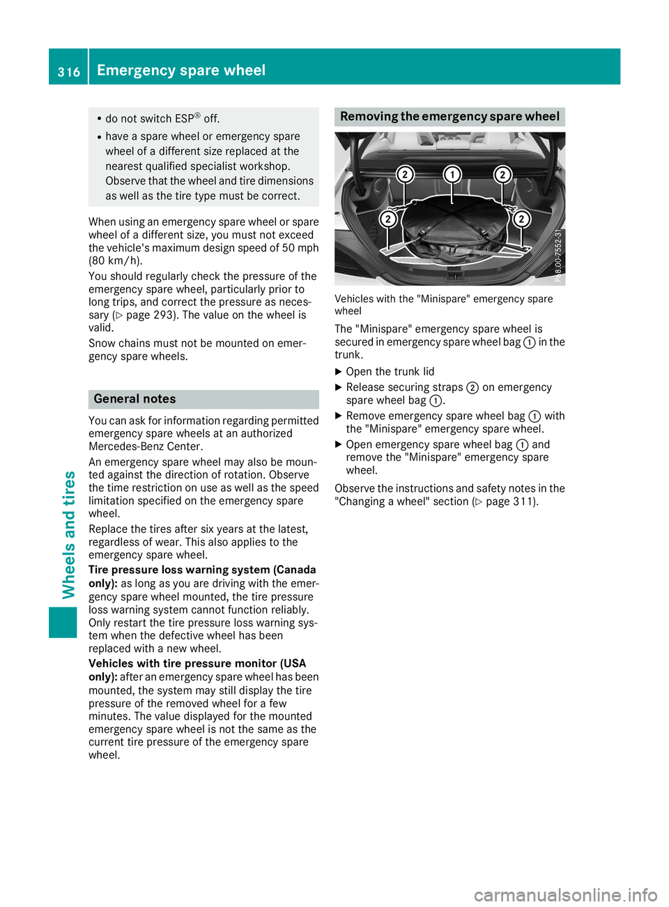
The "Minispar e"emerg encyspare wheel is
secur edinemerg encyspare wheel bag0043inthe
tr unk .
X Open thetrunk lid
X Release securingstraps 0044onemerg ency
spare wheel bag0043.
X Remove emergencyspare wheel bag0043with
the "Minispar e"emerg encyspare wheel.
X Open emerg encyspare wheel bag0043and
remo vethe "Minispar e"emerg encyspare
wheel.
Obser vethe instruct ions andsafet ynot esinthe
"Changin gawheel" section(Ypage 311). 316
Emer
gency sparewheelWheels andtires
Page 319 of 330
Infor
mation reg ardin gtech nicalda ta
i The
datast ate dher espec ifically refers toa
veh iclewit hstand ard equipm ent.Con sult an
auth orizedMer cedes- BenzCen terfor the
dat afor allveh iclevar iantsand trim levels. Veh
icle elect ronics Inst
alling two- way radio sand mob ile
ph ones (RFtrans mitters ) G
WAR
NING
The electromag netic radi ation from two-way
radi oscan interf ere withth eveh icleelec tron -
ics iftwo -way radiosare man ipulat edorret -
rof itte dinc orrectly. This could jeopar dizeth e
oper ating safetyof theveh icle. Ther eis aris k
of an acc iden t.
You should haveall wor kon elec trical and
elec tron icco mpo nentscar ried outataquali-
fie dspec ialist workshop. G
WAR
NING
If you incorrectly oper atetwo-way radiosin
th eveh icle, theelec tromag netic radi ation
may interf ere withth eveh icleelec tron ics ,for
ex ampl eif:
R thetwo -way radiois no tco nn ectedto an
ex terio rant enna
R theex terio rant enna isno tco rrec tly moun -
te dor isno tlow- reflec tion
This could jeopar dizeth eoper ating safetyof
th eveh icle. Ther eis aris kof an acc iden t.
Hav eth elow- reflec tion exterio rant enna
ins talled ataqualif iedspec ialist workshop.
Alw ays conn ecttwo -way radiostothelow-
ref lec tion exterio rant enna when operating in
th eveh icle.
! The
oper ating per mit may beinvalidat edif
th eins truct ionsfor installation and useof
two -way radiosare notobs erved. In
part icular,thefol lowin gco nd ition smust be
co mpli edwith:
R on lyappr ovedwave bandsmay beused
R obs erveth emax imum permis sible output
in these wave bands
R on lyappr ovedant enna pos ition smay be
used
Ex ce ssiv elev els ofelec tromag netic radi ation
may caus edamag eto your healt hand thehealt h
of other s.Usi nganexterio rant enna tak esinto
acc oun tcur ren tsc ien tific disc ussionsrel ating
to thepos sible healthhaz ards that may result
fr om elec tromag netic fie lds. Ap
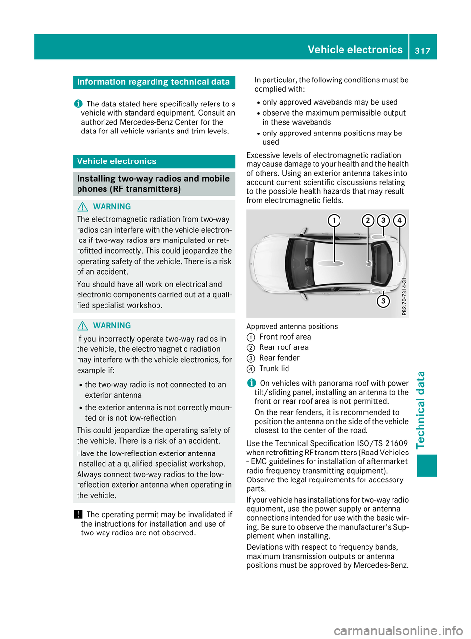
pro ved antenna pos ition s
0043 Fron troo farea
0044 Rear roofarea
0087 Rear fender
0085 Trun klid
i On
veh icles wit hpan oram aroo fwit hpower
ti lt/s lidin gpan el,installingan ant enna tothe
fr on tor rear roofarea isno tper mitted.
On therear fender s,itis rec omm ended to
pos ition theant enna on theside oftheveh icle
clo ses tto thece nter oftheroad .
Use theTec hnical Specific ation ISO/ TS 21609
when retrofitti ng RF trans mitters (Road Vehicles
- EM Cguide lines for installation ofaft erm arket
radi ofrequen cytrans mitting equipm ent).
Obs erveth elegal require men tsfor acc essory
part s.
If your vehiclehas installation sfor two -way radio
equipm ent,use thepower supplyor ant enna
co nn ection sint ended foruse withth ebasic wir-
ing .Be sur eto obs erveth eman ufacturer'sSup -
plem entwhen installing.
De viat ionswit hres pec tto frequen cyban ds,
max imum trans mis sion output sor ant enna
pos ition smust beappr ovedby Mer cedes- Benz. Veh
icle electr onics
317Technical data Z
Page 320 of 330
The
maximum transmission output(PEAK)at the
base ofthe anten namust notexceed thefol-
lowing values: Frequency
band Maximu
m
tra nsmission
outpu t Short
wave
3 -54 MHz 100
W 4
m waveband
74 -88 MHz 30
W 2
m waveband
144 -174 MHz 50
W Trunked
radiosystem/
Tetra
380 -460 MHz 10
W 70
cm waveband
400 -460 MHz 35
W Mobile
commun ications
(2G/3G/4G) 10
W The
following canbeused inthe vehicle without
restr iction s:
R RF trans mitterswith amaximum transmis-
sion output ofup to100 mW
R RF trans mitterswith trans mitterfrequencies
in the 380 -410 MHz frequency bandanda
maximum transmission outputofup to2W
(trunk edradio system/Tet ra)
R Mobile phones (2G/3G/4G)
There isno restr iction foranten napositions on
the outside ofthe vehicle forthe following fre-
quency bands:
R Trunked radiosystem/Tet ra
R 70 cm waveband
R 2G/3G/4 G Identification
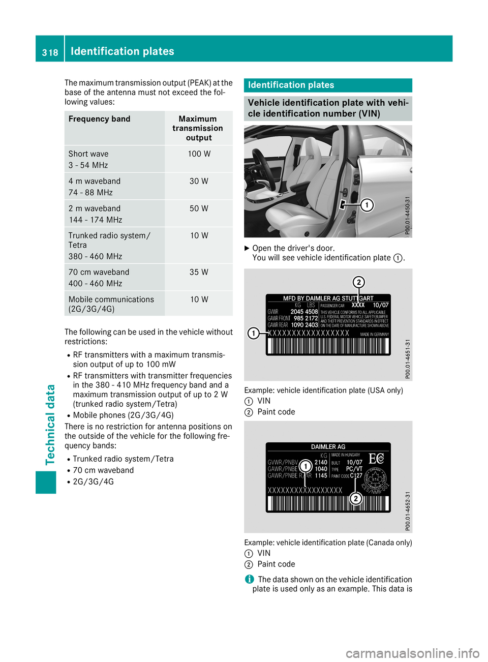
plates Vehicle
identification platewith vehi-
cle identification number(VIN) X
Open thedriver's door.
You willsee vehicle identific ationplate0043. Example:
vehicleidentific ationplate(USA only)
0043 VIN
0044 Paint code Example:
vehicleidentific ationplate(Canada only)
0043 VIN
0044 Paint code
i The
data shown onthe vehicle identific ation
plate isused onlyasan example. Thisdata is 318
Identification
platesTechnical data