lights MERCEDES-BENZ CLA COUPE 2019 Owners Manual
[x] Cancel search | Manufacturer: MERCEDES-BENZ, Model Year: 2019, Model line: CLA COUPE, Model: MERCEDES-BENZ CLA COUPE 2019Pages: 645, PDF Size: 10.94 MB
Page 10 of 645
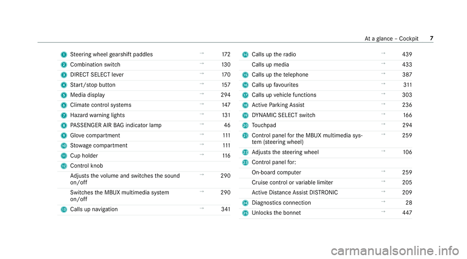
1
Steering wheel gearshift paddles →
172
2 Combination swit ch →
13 0
3 DIRECT SELECT le ver →
17 0
4 Start/ stop button →
157
5 Media display →
294
6 Climate contro l systems →
147
7 Haza rdwa rning lights →
131
8 PASSENGER AIR BAG indicator lamp →
46
9 Glovecompa rtment →
111
A Stow age compartment →
111
B Cup holder →
11 6
C Control knob
Adjusts thevo lume and switches the sound
on/off →
290
Switches the MBUX multimedia sy stem
on/off →
290
D Calls up navigation →
341 E
Calls up thera dio →
439
Calls up media →
433
F Calls up thete lephone →
387
G Calls up favo urites →
311
H Calls up vehicle functions →
303
I Active Parking Assist →
236
J DYNA MIC SELECT switch →
16 6
K Touchpad →
294
L Control panel forth e MBUX multimedia sys‐
te m (s teering wheel) →
259
M Adjusts thesteering wheel →
106
N Control panel for:
On-board computer →
259
Cruise contro l orvariable limiter →
205
Ac tive Dis tance Assi stDISTRONIC →
209
O Diagno stics connection →
28
P Unloc ksthe bonn et →
447 At
aglance – Cockpit 7
Page 14 of 645
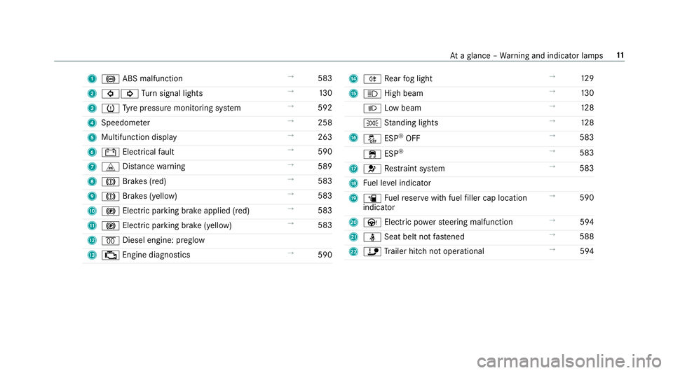
1
! ABS malfunction →
583
2 #! Turn signal lights →
13 0
3 h Tyre pressure monitoring sy stem →
592
4 Speedome ter →
258
5 Multifunction display →
263
6 # Electrical fault →
590
7 L Distance warning →
589
8 J Brakes (red) →
583
9 J Brakes (yellow) →
583
A ! Electric parking brake applied (red) →
583
B ! Electric parking brake (yellow) →
583
C % Diesel engine: preglow
D ; Engine diagno stics →
590 E
R Rear fog light →
12 9
F K High beam →
13 0
L Low beam →
12 8
T Standing lights →
12 8
G å ESP®
OFF →
583
÷ ESP®
→
583
H 6 Restra int sy stem →
583
I Fuel le vel indicator
J æ Fuelreser vewith fuel filler cap location
indicator →
590
K Ù Electric po werst eering malfunction →
594
L ü Seat belt not fastened →
588
M ï Trailer hit chnot operational →
594 At
aglance – Warning and indicator lamps 11
Page 16 of 645
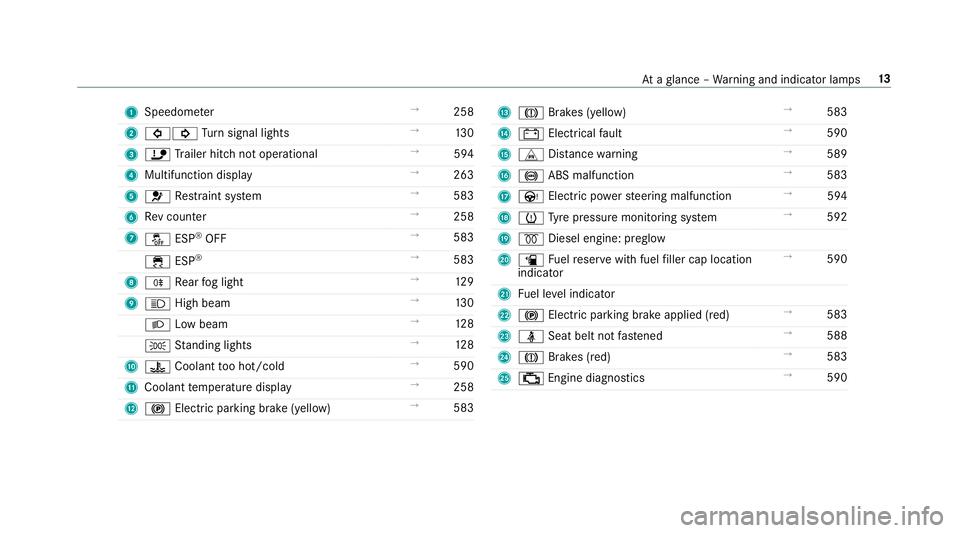
1
Speedom eter →
258
2 #! Turn signal lights →
13 0
3 ï Trailer hit chnot operational →
594
4 Multifunction displ ay →
263
5 6 Restra int sy stem →
583
6 Rev counter →
258
7 å ESP®
OFF →
583
÷ ESP®
→
583
8 R Rear fog light →
12 9
9 K High beam →
13 0
L Low beam →
12 8
T Standing lights →
12 8
A ? Coolant too hot/cold →
590
B Coolant temp erature display →
258
C ! Electric pa rking brake (yellow) →
583 D
J Brakes (yellow) →
583
E # Electrical fault →
590
F L Distance warning →
589
G ! ABS malfunction →
583
H Ù Electric po werst eering malfunction →
594
I h Tyre pressure monitoring sy stem →
592
J % Diesel engine: preglow
K æ Fuelreser vewith fuel filler cap location
indicator →
590
L Fuel le vel indicator
M ! Electric parking brake applied (red) →
583
N ü Seat belt not fastened →
588
O J Brakes (red) →
583
P ; Engine diagnostics →
590 At
aglance – Warning and indicator lamps 13
Page 22 of 645
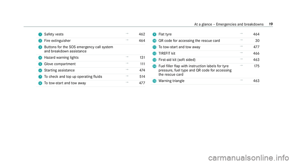
1
Safetyve sts →
462
2 Fire extinguisher →
464
3 Buttons forth e SOS emer gency call sy stem
and breakdown assis tance
4 Haza rdwa rning lights →
131
5 Glovecompa rtment →
111
6 Starting assis tance →
474
7 Tocheck and top up operating fluids →
514
8 Totow- start and tow aw ay →
477 9
Flat tyre →
464
A QR code for accessing there scue card →
30
B Totow- start and tow aw ay →
477
C TIREFIT kit →
466
D First-aid kit (so ftsided) →
463
E Fuelfiller flap with instruction labels for tyre
pressu re, fuel type and QR code for accessing
th ere scue card →
175
F Warning triangle →
463 At
aglance – Emer gencies and breakdowns 19
Page 34 of 645
driving (driver assis
tance sy stems). In addition,
yo ur vehicle pr ovides com fort and enter tainment
functions, which are also made possible byelec‐
tronic control units.
Elect ronic control units contain da tamemories
which can temp orarily or permanently store
te ch nical information about theve hicle's operat‐
ing state, component loads, main tenance
re qu irements and tech nical events or faults.
In general, this information documents thest ate
of a component part, a module, a sy stem or the
sur roundings such as:
R operating status of sy stem components (e.g.
fi ll le vels, battery status, tyre pressure)
R status messages concerning theve hicle or
its individual components (e.g. number of
wheel revo lutions/speed, longitudinal accel‐
eration, lateral acceleration, display of fas‐
te ned seat belts)
R malfunctions or faults in impor tant sy stem
components (e.g. lights, brakes)
R information on events leading tovehicle
damage R
system reactions in special driving situations
(e.g. airbag deployment, inter vention of sta‐
bility control sy stems)
R ambient conditions (e.g. temp erature, rain
sensor)
In addition toprov iding the actual control unit
function, this data assists the manufacturer in
de tecting and rectifying faults and optimising
ve hicle functions. The majority of this data is
te mp orary and is only processed in theve hicle
itself. Only a small portion of the data is stored
in theeve nt or fault memor y.
When your vehicle is serviced, tech nical da ta
from theve hicle can be read out byservice net‐
wo rkemplo yees (e.g. workshops, manufactur‐
ers) or third parties (e.g. breakdown services).
Services include repair services, maintenance
processes, warranty claims and quality assur‐
ance measures, forex ample. The read out is per‐
fo rm ed via the legally prescribed port forthe
diagnostics connection in theve hicle. The
re spective service network locations or third
parties collect, process and use the data. They
document tech nical statuses of theve hicle, assist in
finding faults and impr oving quality and
are transmitted tothe manufacturer, if neces‐
sar y.Fu rthermore, the manufacturer is subject
to product liability. Forth is, the manufacturer
requ irestech nical da tafrom vehicles.
Fa ult memories in theve hicle can be reset by a
service outlet as part of repair or maintenance
wo rk.
Depending on the selected equipment, you can
import data into theve hicle's comfort and info‐
ta inment functions yourself.
This includes, forex ample:
R multimedia data such as music, films or pho‐
to sfo r playback in an integrated multimedia
sy stem
R address book data for use in connection with
an integrated hands-free sy stem or an inte‐
grated navigation sy stem
R entered navigation destinations
R data about the use of Internet services
This data can be sa ved locally in theve hicle or it
is located on a device which you ha veconnected
to theve hicle (e.g. smartphone, USB flash drive Gene
ral no tes 31
Page 38 of 645
Re
stra int sy stem functionality When
the ignition is switched on, a self-test is
per form ed, during which the6 restra int sys‐
te m wa rning lamp lights up. It goes out no later
th an a few seconds af terth eve hicle is star ted.
The components of there stra int sy stem are then
functional. Malfunctioning
restra int sy stem A malfunction has occur
red in there stra int sys‐
te m if:
R the6 restra int sy stem warning lamp does
not light up when the ignition is switched on
R the6 restra int sy stem warning lamp
lights up continuously or repeatedly during a
journey &
WARNING Risk of inju rydue tomalfunc‐
tions in there stra int sy stem
If th ere stra int sy stem is malfunctioning,
re stra int sy stem components may be trig‐
ge red unintentionally or may not deploy as intended during an accident. This may af
fect
th e seat belt tensioner or airbag, forex am‐
ple. #
Have there stra int sy stem checked and
re paired immediately at a qualified spe‐
cialist workshop. Fu
nction of there stra int sy stem in an acci‐
dent How
there stra int sy stem works is de term ined by
th e se verity of the impact de tected and the type
of accident anticipated:
R Frontal impact
R Rear impact
R Side impact
R Onlyfor cer tain countries: rollo ver
The activation thre sholds forth e components of
th ere stra int sy stem are de term ined based on
th eev aluation of the sensor values measured at
va rious points in theve hicle. This process is pre-
em ptive in nature. The triggering/deployment of
th e components of there stra int sy stem must ta
ke place in good time at thest art of the colli‐
sion.
Fa ctors whi chcan only be seen and measu red
af te r a collision has occur red do not play a deci‐
sive role in the deployment of an airbag. Nordo
th ey prov ide an indication of airbag deployment.
The vehicle may be deformed significantly with‐
out an airbag being deplo yed. This is the case if
only parts which are relatively easily deformed
are af fected and thera te ofvehicle deceleration
is not high. Con versely, an airbag may be
deplo yedev en though theve hicle suf fers only
minor deformation. If very rigid vehicle parts
such as longitudinal members are hit, forex am‐
ple, this may result in suf ficiently high le vels of
ve hicle deceleration. Occupant saf
ety35
Page 49 of 645
Fu
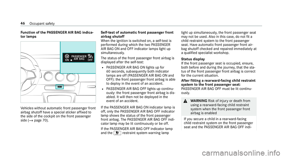
nction of thePA SSENGER AIR BAG indica‐
to r lamps Ve
hicles without automatic front passenger front
airbag shutoff ha vea special sticke r af fixe dto
th e side of the cockpit on the front passenger
side (/ page 70). Self-test of automatic front passenger front
airbag shutoff
When
the ignition is switched on, a self-test is
per form ed during which the two PASSENGER
AIR BAG ON and OFF indicator lamps light up
simul taneously.
The status of the front passenger front airbag is
displa yed af terth e self-tes t:
R PASSENGER AIR BAG ON lights up for
60 seconds, subsequently bo thindicator
lamps are off (PASSENGER AIR BAG ON and
OFF): the front passenger front airbag is able
to deploy in theeve nt of an accident.
R PASSENGER AIR BAG OFF lights up continu‐
ously: the front passenger front airbag is dis‐
abled. It will then not be deplo yed in the
eve nt of an accident.
If th ePA SSENGER AIR BAG ON indicator lamp is
off, on lythePA SSENGER AIR BAG OFF indicator
lamp sho ws thest atus of the front passenger
front airbag. The PASSENGER AIR BAG OFF indi‐
cator lamp may be lit continuously or be off.
If th ePA SSENGER AIR BAG OFF indicator lamp
and the6 restra int sy stem warning lamp light up simultaneousl
y,the front passenger seat
may not be used. Also in this case, do not fit a
ch ild restra int sy stem tothe front passenger
seat. Ha veautomatic front passenger front air‐
bag shutoff checked and repaired immediately at
a qu alified specialist workshop.
St atus display
If th e front passenger seat is occupied, ensure,
bo th before and during the journe y,that thest a‐
tus of the front passenger front airbag is cor rect
fo rth e cur rent situation.
Af terfitting a rear wa rd-facing child restra int
sy stem tothe front passenger seat:
PA SSENGER AIR BAG OFF must be lit continu‐
ousl y. &
WARNING Risk of inju ryor death from
using a rear wa rd-facing child restra int
sy stem when the front passenger front
airbag is enabled
If yo u secure a child in a rear wa rd-facing
ch ild restra int sy stem on the front passenger
seat and thePA SSENGER AIR BAG OFF indi‐ 46
Occupant saf ety
Page 51 of 645
If
th ePA SSENGER AIR BAG OFF indicator
lamp is lit continuousl y,an adult or person
with a build cor responding tothat of an adult
should not use the front passenger seat.
Ins tead, they should use a rear seat.
R Ifth e front passenger seat is occupied by a
person of smaller stature (e.g. a teenager or
small adult), thePA SSENGER AIR BAG OFF
indicator lamp either lights up continuously
or remains off, depending on there sult of the
classi fication.
- Ifth ePA SSENGER AIR BAG OFF indicator
lamp is off: mo vethe front passenger
seat as far back as possible, or the per‐
son of smaller stature should use a rear
seat.
- Ifth ePA SSENGER AIR BAG OFF indicator
lamp is lit continuously: the person of
smaller stature should not use the front
passenger seat. &
WARNING Risk of inju ryor death when
th ePA SSENGER AIR BAG OFF indicator
lamp is lit
If th ePA SSENGER AIR BAG OFF indicator
lamp remains lit af terth e sy stem self-test,
th e front passenger airbag is disabled. It will
not be deplo yed in theeve nt of an accident.
In this case, the front passenger airbag can‐
not per form its intended pr otective function,
e.g. when a person is seated in the front
passenger seat.
That person could, forex ample, come into
con tact wi th theve hicle interior, especially if
th e person is sitting too close tothe cockpit.
If th e front passenger seat is occupied,
alw ays ensure that:
R The classification of the person in the
front passenger seat is cor rect and the
front passenger airbag is enabled or disa‐
bled in accordance with the person in the
front passenger seat. R
The person is sea ted proper lywith a cor‐
re ctly fastened seat belt.
R The front passenger seat has been mo ved
as far back as possible. Be sure
toalso obse rveth efo llowing fur ther
re lated subjects:
R Child restra int sy stem on the front passenger
seat (/ page71).
R Suitable positioning of thech ild restra int sys‐
te m (/ page 56). PRE-SAFE
®
sy stem PRE-
SAFE®
(anticipa tory occupant pr otec‐
tion) PRE-
SAFE®
is able todetect cer tain critical driv‐
ing situations and implement pre-em ptive meas‐
ures toprotect theve hicle occupants.
PRE-SAFE ®
can implement thefo llowing meas‐
ures independently of each other:
R Tightening the seat belts on the driver's seat
and front passenger seat. 48
Occupant saf ety
Page 52 of 645
R
Closing the side windo ws.
R Vehicles with sliding sunroof: closingthe
sliding sunroof.
R Vehicles with memory function: moving
th e front passenger seat toa more favo ura‐
ble seat position.
R PRE-SAFE ®
Sound: pr ovided that the multi‐
media sy stem is switched on, generates a
brief noise signal tostimulate the innate pro‐
te ctive mechanism of a person's hea ring.
* NO
TEDama gecaused byobjects in the
fo ot we ll or behind the seat The automatic adjustment of
the seat posi‐
tion may result in damage tothe seat and/or
th e object. #
Stow objects in a suitable place. Re
versing the PRE- SAFE®
sy stem measures If an accident did not occur,
the pre-em ptive
measures that we retak en are reve rsed. Yo
u will need toper form certain settings your‐
self. #
Ifth e seat belt pre-tensioning is not reduced,
mo vethe seat backrest back slightl y.
The locking mechanism releases. Fu
nction of PRE-SAFE ®
PLUS (anticipatory
occupant pr otection plus) PRE-
SAFE®
PLUS can de tect cer tain impacts,
particular lyan imminent rear impact, and take
pre-em ptive measures toprotect theve hicle
occupants. These measures cannot necessarily
pr eve nt an imminent impact.
PRE-SAFE ®
PLUS can implement thefo llowing
measures independently of each other:
R Tightening the seat belts on the driver's seat
and front passenger seat.
R Activating there ar hazard warning lights at a
higher flashing frequenc y.
R Increasing brake pressure when theve hicle
is stationar y.This brake application is cancel‐
led automatically when theve hicle pulls
aw ay. If an accident did not occur,
the pre-em ptive
measures that we retake n are reve rsed.
Sy stem limitations
The sy stem will not initiate any action in thefo l‐
lowing situations:
R when reve rsing
or
R when theve hicle is towing a trailer and there
is a risk of a rear impact
The sy stem will not initiate any braking applica‐
tion in thefo llowing situations:
R whilst driving
or
R when entering or exiting a parking space
while using Active Parking Assist Occupant saf
ety49
Page 80 of 645
The indicator lamp in
the door trim on the driv‐
er's side flashes when theve hicle is loc ked from
outside. The indicator lamp goes out if theve hi‐
cle is loc ked from inside or while theve hicle is in
motion.
If th eve hicle is not opened within appr oximately
40 seconds af ter unlocking, it loc ksagain. Anti-
th eft pr otection is primed again.
Do not keep theke yto ge ther with electronic
devices or me tal objects. This can af fect the
ke y's functionalit y.
% If battery check lamp 2does not light up
af te r pressing theÜ orß button, the
battery is dischar ged.
Changing theke y bat tery ( / page 78). Ac
tivating/deactivating the acoustic lo cking
ve rification signal Multimedia sy
stem:
4 © 5
Settings 5
Vehicle #
Activate or deacti vate Acoustic lock .
% Please no
te: The selected setting
forth e acoustic locking
ve rification signal must comply wi th there le‐
va nt national road and traf fic re gulations. In
some countri es, including German y,using
th e acoustic locking verification signal is for‐
bidden bytraf fic la ws(in accordance with
§16 Para. 1 and §30 Para. 1 of the German
national road traf fic re gulations). The driver
of theve hicle must comply with these regu‐
lations. In countri es wherethe use of this
function is forbidden, this function is not
activated in theve hicle and must not be acti‐
va ted. Changing
the unlocking settings Po
ssible unlocking functions of theke y:
R cent ral unlocking
R unlocking the driver's door and fuel filler flap #
Toswitch between settings: pressthe
Ü andß buttons simultaneously for
appr oximately six seconds until the battery
ch eck lamp flashes twice. If
th e unlocking function forth e driver's door
and fuel filler flap has been selec ted:
R pressing theÜ button a second time cen‐
trally unloc kstheve hicle
R Vehicles with KEYLESS-GO: ifyo uto uch
th e inner sur face of the door handle on the
driver's door, only the driver's door and fuel
fi ller flap are unlo cked. Deactivating
theke y functions If
yo u do not use theve hicle or a keyfo r an
ex tended pe riod of time, you can reduce the
energy consum ption of there spective key.Todo
so, deactivate theke y functions. #
Todeactivate: presstheß button on the
ke y twice in quick succession.
The battery check lamp of theke yflashes
twice brief lyand lights up once. #
Toactivate: press any button on thekey.
% When theve hicle is star ted with theke y in
th estow age compartment of the cent recon‐
sole, theke y functions are automatical ly
activated (/ page159). Opening and
closing77