electrical MERCEDES-BENZ CLK CABRIOLET 2000 A208 Owner's Manual
[x] Cancel search | Manufacturer: MERCEDES-BENZ, Model Year: 2000, Model line: CLK CABRIOLET, Model: MERCEDES-BENZ CLK CABRIOLET 2000 A208Pages: 323, PDF Size: 9.32 MB
Page 56 of 323
Seats
Te ch n ica l
data Instruments
and controlsOperationDrivingInstrument
cluster displayPractical hints Car care Index Notes:
When in operation, the seat heater consumes a large
amount of electrical power. It is not advisable to use the
seat heater longer than necessary.
The seat heaters may automatically switch off if too
many power consumers are switched on at the same
time, or if the battery charge is low. When this occurs,
the indicator lamp in the switch will blink (both
indicator lamps blink during rapid seat heating mode).
The seat heaters will switch on again automatically as
soon as sufficient voltage is available.
If the blinking of the indicator lamps is distracting to
you, the seat heaters can be switched off.
56
Page 70 of 323
Restraint systems
Te ch n ica l
data Instruments
and controlsOperationDrivingInstrument
cluster displayPractical hints Car care Index
• Children 12 years old and under must never
ride in the front seat, except in a
Mercedes-Benz authorized BabySmart
TM
compatible child seat, which operates with the
BabySmart
TM system installed in the vehicle to
deactivate the passenger front airbag when it
is properly installed. Otherwise they will be
struck by the airbag when it inflates in a crash.
If this happens, serious or fatal injury can
result.
Failure to follow these instructions can result in
severe or fatal injuries to you or other occupants.
Safety guidelines for the seat belt,
emergency tensioning retractor and airbag
Wa r n i n g !
• Damaged seat belts or belts that were highly
stressed in an accident must be replaced and
their anchoring points must also be checked.
Use only belts installed or supplied by an
authorized Mercedes-Benz Center.
• Do not pass belts over sharp edges.• Do not make any modification that could
change the effectiveness of the belts.
• Airbags and ETR’s are designed to function on
a one-time-only basis. An airbag or emergency
tensioning retractor (ETR) that was activated
must be replaced.• No modifications of any kind may be made to
any components or wiring of the “SRS”. This
includes changing or removing any component
or part of the “SRS”, the installation of
additional trim material, badges etc. over the
steering wheel hub, front passenger airbag
cover, or front door trim panels, and
installation of additional electrical/electronic
equipment on or near “SRS” components and
wiring. Keep area between airbags and
occupants free of objects (e.g. packages,
purses, umbrellas, etc.).• An airbag system component within the
steering wheel gets hot after the airbag has
inflated. Do not touch.• Improper work on the system, including
incorrect installation and removal, can lead to
possible injury through an unintended
activation of the “SRS”.
70
Page 76 of 323
Rear view mirrors
Te ch n ica l
data Instruments
and controlsOperationDrivingInstrument
cluster displayPractical hints Car care Index
Exterior rear view mirrors
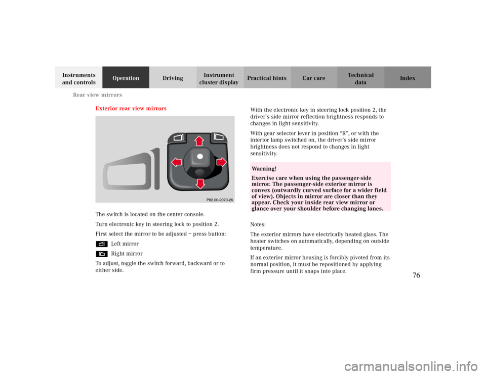
The switch is located on the center console.
Turn electronic key in steering lock to position 2.
First select the mirror to be adjusted – press button:
%Left mirror
&Right mirror
To adjust, toggle the switch forward, backward or to
either side.
1With the electronic key in steering lock position 2, the
driver’s side mirror reflection brightness responds to
changes in light sensitivity.
With gear selector lever in position “R”, or with the
interior lamp switched on, the driver’s side mirror
brightness does not respond to changes in light
sensitivity.
Notes:
The exterior mirrors have electrically heated glass. The
heater switches on automatically, depending on outside
temperature.
If an exterior mirror housing is forcibly pivoted from its
normal position, it must be repositioned by applying
firm pressure until it snaps into place.
Wa r n i n g !
Exercise care when using the passenger-side
mirror. The passenger-side exterior mirror is
convex (outwardly curved surface for a wider field
of view). Objects in mirror are closer than they
appear. Check your inside rear view mirror or
glance over your shoulder before changing lanes.
76
Page 122 of 323
Automatic climate control
Te ch n ica l
data Instruments
and controlsOperationDrivingInstrument
cluster displayPractical hints Car care Index
Rear window defroster
Turn electronic key in steering lock to position 2.
To select, press F button.
To cancel, press F button again.
Notes:
Heavy accumulation of snow and ice should be removed
before activating the defroster.
The rear window defroster consumes a large amount of
electrical power. To keep the battery drain to a
minimum, turn off the defroster as soon as the window
is clear.
The defroster is automatically turned off after a
maximum of 12 minutes of operation.
If several power consumers are turned on
simultaneously, or the battery is only partially charged,
it is possible that the defroster will automatically turn
itself off. When this happens, the indicator lamp inside
the switch starts blinking.
As soon as the battery has sufficient voltage, the
defroster automatically turns itself back on.Air distribution
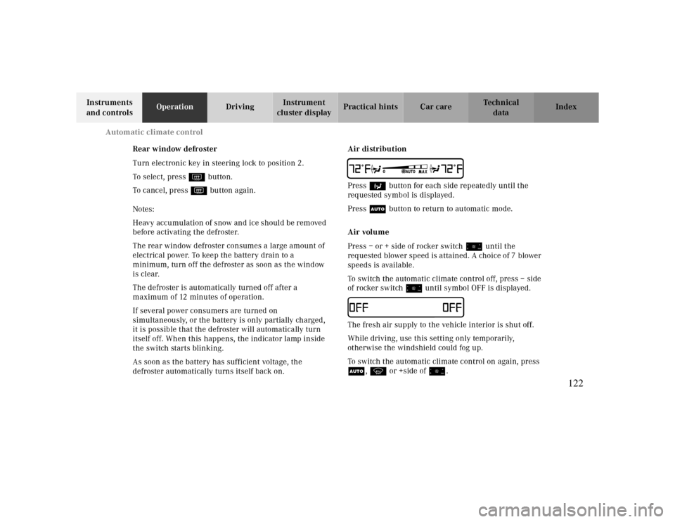
TPress b button for each side repeatedly until the
requested symbol is displayed.
Press U button to return to automatic mode.
Air volume
Press – or + side of rocker switch ï until the
requested blower speed is attained. A choice of 7 blower
speeds is available.
To switch the automatic climate control off, press – side
of rocker switch ï until symbol OFF is displayed.IThe fresh air supply to the vehicle interior is shut off.
While driving, use this setting only temporarily,
otherwise the windshield could fog up.
To switch the automatic climate control on again, press
U, P or +side of ï.
122
Page 151 of 323
Interior equipment
Te ch n ica l
data Instruments
and controlsOperationDrivingInstrument
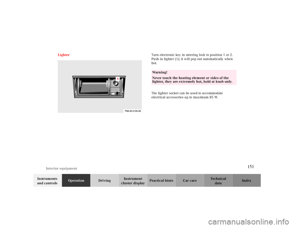
cluster displayPractical hints Car care Index LighterTurn electronic key in steering lock to position 1 or 2.
Push in lighter (1); it will pop out automatically when
hot.
The lighter socket can be used to accommodate
electrical accessories up to maximum 85 W.
Wa r n i n g !
Never touch the heating element or sides of the
lighter, they are extremely hot, hold at knob only.
151
Page 180 of 323
Steering lock
Te ch n ica l
data Instruments
and controlsOperationDrivingInstrument
cluster displayPractical hints Car care Index
Steering lock
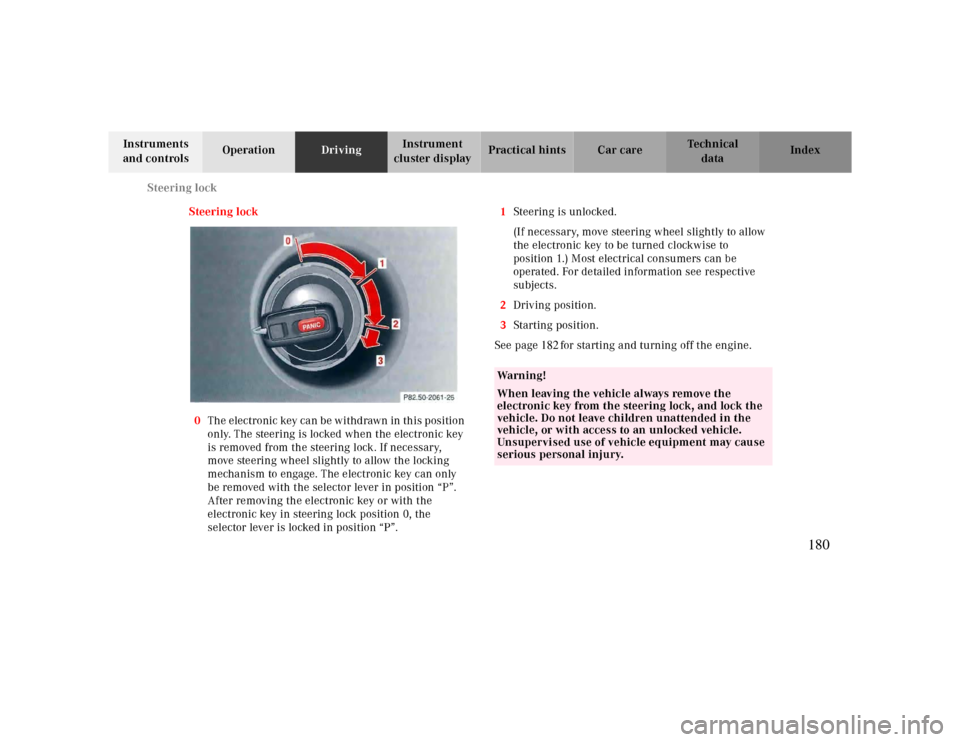
0The electronic key can be withdrawn in this position
only. The steering is locked when the electronic key
is removed from the steering lock. If necessary,
move steering wheel slightly to allow the locking
mechanism to engage. The electronic key can only
be removed with the selector lever in position “P”.
After removing the electronic key or with the
electronic key in steering lock position 0, the
selector lever is locked in position “P”.1Steering is unlocked.
(If necessary, move steering wheel slightly to allow
the electronic key to be turned clockwise to
position 1.) Most electrical consumers can be
operated. For detailed information see respective
subjects.
2Driving position.
3Starting position.
See page182for starting and turning off the engine.
Wa r n i n g !
When leaving the vehicle always remove the
electronic key from the steering lock, and lock the
vehicle. Do not leave children unattended in the
vehicle, or with access to an unlocked vehicle.
Unsupervised use of vehicle equipment may cause
serious personal injury.
180
Page 181 of 323
Steering lock
Te ch n ica l
data Instruments
and controlsOperationDrivingInstrument
cluster displayPractical hints Car care Index Important!
If the electronic key is left in the steering lock position 0
for an extended period of time, it can no longer be
turned in the lock. In this case, remove electronic key
from steering lock and reinsert.
Caution!
To prevent accelerated battery discharge and a possible
dead battery, always remove the electronic key from the
steering lock. Do not leave the electronic key in steering
lock position 0.Notes:
A warning sounds when the driver’s door is opened
while the electronic key is in steering lock position 1
or 0.
With the engine at idle speed, the charging rate of the
alternator (output) is limited.
It is therefore recommended that you turn off
unnecessary electrical consumers while driving in stop-
and-go traffic. This precaution helps to avoid draining of
the battery.
Unnecessary strain on the battery and charging system
may be minimized by turning off the following power
consumers, for example: Heated seats, rear window
defroster. In addition, the automatic climate air volume
control should be set to the lowest position.
The steering lock can only be unlocked with the vehicle
battery properly charged and connected.
181
Page 186 of 323
Automatic transmission
Te ch n ica l
data Instruments
and controlsOperationDrivingInstrument
cluster displayPractical hints Car care Index
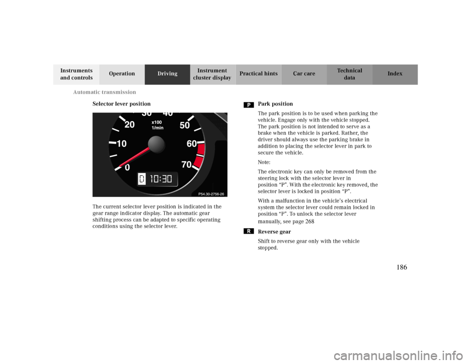
Selector lever position
The current selector lever position is indicated in the
gear range indicator display. The automatic gear
shifting process can be adapted to specific operating
conditions using the selector lever.Park position
The park position is to be used when parking the
vehicle. Engage only with the vehicle stopped.
The park position is not intended to serve as a
brake when the vehicle is parked. Rather, the
driver should always use the parking brake in
addition to placing the selector lever in park to
secure the vehicle.
Note:
The electronic key can only be removed from the
steering lock with the selector lever in
position “P”. With the electronic key removed, the
selector lever is locked in position “P”.
With a malfunction in the vehicle’s electrical
system the selector lever could remain locked in
position “P”. To unlock the selector lever
manually, see page268
Reverse gear
Shift to reverse gear only with the vehicle
sto p ped .
10
186
Page 199 of 323
Driving instructions
Te ch n ica l
data Instruments
and controlsOperationDrivingInstrument
cluster displayPractical hints Car care Index
Winter driving
Have your vehicle winterized at your authorized
Mercedes-Benz Center before the onset of winter.
•Change the engine oil if the engine contains an oil
which is not approved for winter operation. For
viscosity (SAE/CCMC class) and filling quantity, see
page307.
•Check engine coolant anticorrosion/antifreeze
concentration.
•Additive for the windshield washer and headlamp
cleaning system: Add MB Concentrate “S” to a
premixed windshield washer solvent/antifreeze
which is formulated for below freezing temperatures
see page249.
•Test battery: Battery capacity drops with decreasing
ambient temperature. A well charged battery helps
to ensure that the engine can be started, even at low
ambient temperatures.
•Tires: We recommend M+S rated radial-ply tires on
all four wheels for the winter season. Observe
permissible maximum speed for M+S rated
radial-ply tires and the legal speed limit.In winter operation, the maximum effectiveness of the
antilock brake system (ABS) or of the electronic stability
program (ESP) can only be achieved with M+S rated
radial-ply tires and / or snow chains recommended by
Mercedes-Benz. Snow chains maximize performance.
For driving instructions with snow chains, see page198.
Deep water
Caution!
Do not drive through flooded areas or water of unknown
depth.
If you must drive through deep water, drive slowly to
prevent water from entering the engine compartment or
passenger compartment, being ingested by the air
intake, possibly causing damage to electrical
components or wiring, to engine or transmission that is
not covered by the Mercedes-Benz Limited Warranty.
199
Page 261 of 323
Battery
Te ch n ica l
data Instruments
and controlsOperation DrivingInstrument
cluster displayPractical hintsCar care Index
Battery
Important!
Battery replacement information:
The maintenance-free battery is located in the trunk
under the trunk floor.
The service life of the battery is dependent on its
condition of charge. The battery should always be kept
sufficiently charged, in order to last an optimum length
of time.
Wa r n i n g !
Failure to follow these instructions can result in
severe injury or death.Never lean over batteries while connecting, you
might get injured.Battery fluid contains sulfuric acid. Do not allow
this fluid to come in contact with eyes, skin or
clothing. In case it does, immediately flush affected
area with water and seek medical help if necessary.A battery will also produce hydrogen gas, which is
flammable and explosive. Keep flames or sparks
away from battery, avoid improper connection of
jumper cables, smoking etc..Therefore, we strongly recommend that you have the
battery charge checked frequently, and corrected if
necessary, especially if you use the vehicle less than
approximately 200 miles (300 km) per month,
mostly for short distance trips, or if it is not used for
long periods of time.
Only charge a battery with a battery charger after the
battery has been disconnected from the vehicle’s
electrical circuit.
Always disconnect the battery negative lead first and
connect last.
When removing and connecting the battery, always
make sure that all electrical consumers are off and the
electronic key is in steering lock position 0. The battery
and its filler caps must always be securely installed
when the vehicle is in operation. During removal and
installation always protect the disconnected battery
positive (+) terminal with the cover attached to the
battery.
While the engine is running the battery terminal clamps
must not be loosened or detached, otherwise the
generator and other electronic components would be
damaged.
261