electrical MERCEDES-BENZ CLK CABRIOLET 2000 A208 User Guide
[x] Cancel search | Manufacturer: MERCEDES-BENZ, Model Year: 2000, Model line: CLK CABRIOLET, Model: MERCEDES-BENZ CLK CABRIOLET 2000 A208Pages: 323, PDF Size: 9.32 MB
Page 263 of 323
Jump starting
Te ch n ica l
data Instruments
and controlsOperation DrivingInstrument
cluster displayPractical hintsCar care Index
Jump starting
If the battery is discharged, the engine should be started
with jumper cables and the (12 V) battery of another
vehicle.
Only use 12 V battery to jump start your vehicle. Jump
starting with more powerful battery could damage the
vehicle’s electrical systems, which will not be covered
by the Mercedes-Benz Limited Warranty.
The battery is located in the trunk under the trunk floor.
Warning!
Failure to follow these directions will cause
damage to the electronic components, and can lead
to a battery explosion and severe injury or death.Never lean over batteries while connecting or jump
starting, you might get injured.Battery fluid contains sulfuric acid. Do not allow
this fluid to come in contact with eyes, skin or
clothing. In case it does, immediately flush affected
area with water, and seek medical help if
necessary.A battery will also produce hydrogen gas, which is
flammable and very explosive. Keep flames or
sparks away from battery, avoid improper
connection of jumper cables, smoking etc..Read all instructions before proceeding.Proceed as follows:
1. Position the vehicle with the charged battery so that
the jumper cables will reach, but never let the
vehicles touch. Make sure the jumper cables do not
have loose or missing insulation.
2. On both vehicles:
•Turn off engine and all lights and accessories,
except hazard warning flashers or work lights.
•Apply parking brake and shift selector lever to
position “P”.
263
Page 269 of 323
Exterior lamps
Te ch n ica l
data Instruments
and controlsOperation DrivingInstrument
cluster displayPractical hintsCar care Index
Bulbs
Headlamp adjustment
Correct headlamp adjustment is extremely important.
Check and readjust headlamps at regular intervals and
when a bulb has been replaced.
For adjusting headlamp aim see page274.
Replacing bulbsNotes:
To prevent a possible electrical short circuit, switch off
lamp prior to replacing a bulb.
When replacing bulbs, install only 12 volt bulbs with
the specified watt rating.
When replacing halogen bulbs do not touch glass
portion of bulb with bare hands. Use plain paper or a
clean cloth.
Warning!
Bulbs and bulb holders can be very hot. Allow the
lamp to cool down before changing a bulb.
Halogen lamps contain pressurized gas. A bulb can
explode if you:
• touch or move it when hot,
• drop the bulb,
• scratch the bulb.Wear eye and hand protection.
Wa r n i n g !
Because of high voltage in Xenon lamps, it is
dangerous to replace the bulb or repair the lamp
and its components. We recommend that you have
such work done by a qualified technician.
269
Page 270 of 323
Exterior lamps
Te ch n ica l
data Instruments
and controlsOperation DrivingInstrument
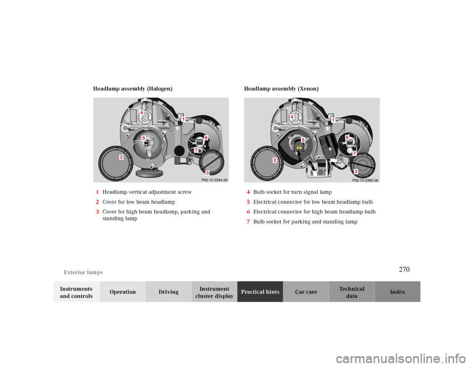
cluster displayPractical hintsCar care Index Headlamp assembly (Halogen)
1Headlamp vertical adjustment screw
2Cover for low beam headlamp
3Cover for high beam headlamp, parking and
standing lampHeadlamp assembly (Xenon)
4Bulb socket for turn signal lamp
5Electrical connector for low beam headlamp bulb
6Electrical connector for high beam headlamp bulb
7Bulb socket for parking and standing lamp
P82.10-2394-26
4
1
5
6
7
2
3
4
6
7
2
3P82.10-2395-26
5
1
270
Page 271 of 323
Exterior lamps
Te ch n ica l
data Instruments
and controlsOperation DrivingInstrument
cluster displayPractical hintsCar care Index
Bulbs for low or high beam
H7 (55 W)
Open hood.
Rotate cover (2 or 3) counterclockwise and remove. Pull
off electrical connector (5 or 6). Unhook clamping ring
and remove bulb.
Insert new bulb (seating properly in cutouts of bulb
socket), mount clamping ring. Reinstall and push
electrical connector on securely.
Reinstall cover (2 or 3).
Xenon (optional)
Bulb for low beamTurn signal lamp
1156 NA (26.9/5 W/32/4 cp bulb)
Open hood.
Twist bulb socket (4) counterclockwise and pull out.
Push bulb into socket, turn counterclockwise and
remove.
Insert new bulb in socket, push in and twist clockwise.
Reinstall bulb socket. Reinstall lamp assembly until
properly seated.
Parking and standing lamp
H6W (6Wbulb)
Open hood.
Rotate cover (3) counterclockwise and remove.
Twist bulb socket (7) counterclockwise and pull out.
Push bulb into socket, turn counterclockwise and
remove.
Insert new bulb in socket, push in and twist clockwise.
Reinstall bulb socket. Reinstall lamp assembly until
properly seated.
Reinstall cover (3).
Warning!
Because of high voltage in Xenon lamps, it is
dangerous to replace the bulb or repair the lamp
and its components. We recommend that you have
such work done by a qualified technician.
271
Page 293 of 323
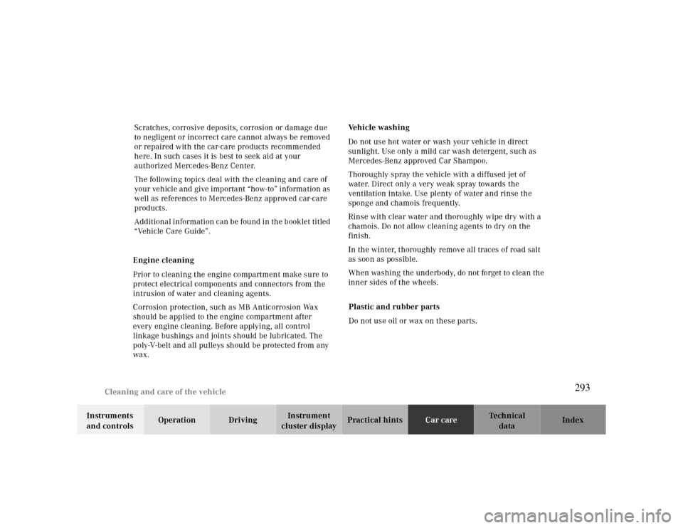
Cleaning and care of the vehicle
Te ch n ica l
data Instruments
and controlsOperation DrivingInstrument
cluster displayPractical hintsCar careIndex Scratches, corrosive deposits, corrosion or damage due
to negligent or incorrect care cannot always be removed
or repaired with the car-care products recommended
here. In such cases it is best to seek aid at your
authorized Mercedes-Benz Center.
The following topics deal with the cleaning and care of
your vehicle and give important “how-to” information as
well as references to Mercedes-Benz approved car-care
products.
Additional information can be found in the booklet titled
“Vehicle Care Guide”.
Engine cleaning
Prior to cleaning the engine compartment make sure to
protect electrical components and connectors from the
intrusion of water and cleaning agents.
Corrosion protection, such as MB Anticorrosion Wax
should be applied to the engine compartment after
every engine cleaning. Before applying, all control
linkage bushings and joints should be lubricated. The
poly-V-belt and all pulleys should be protected from any
wax.Vehicle washing
Do not use hot water or wash your vehicle in direct
sunlight. Use only a mild car wash detergent, such as
Mercedes-Benz approved Car Shampoo.
Thoroughly spray the vehicle with a diffused jet of
water. Direct only a very weak spray towards the
ventilation intake. Use plenty of water and rinse the
sponge and chamois frequently.
Rinse with clear water and thoroughly wipe dry with a
chamois. Do not allow cleaning agents to dry on the
finish.
In the winter, thoroughly remove all traces of road salt
as soon as possible.
When washing the underbody, do not forget to clean the
inner sides of the wheels.
Plastic and rubber parts
Do not use oil or wax on these parts.
293
Page 305 of 323
Technical data
Te ch n ica l
data Instruments
and controlsOperation DrivingInstrument
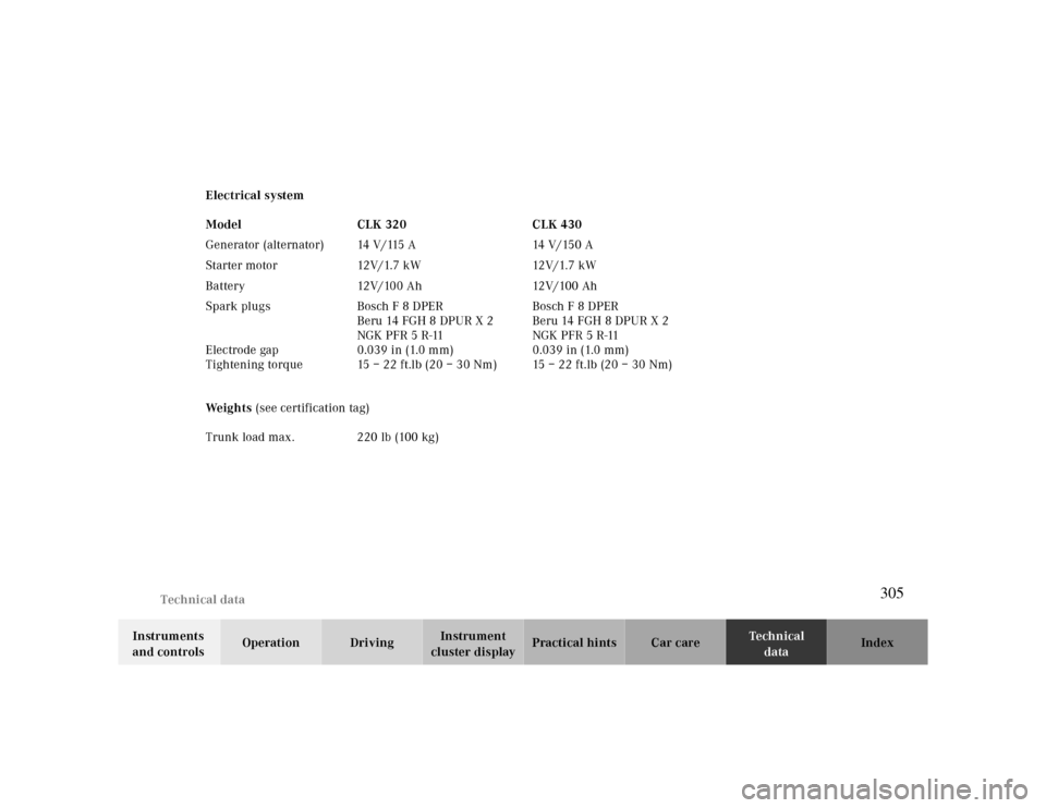
cluster displayPractical hints Car care Index Electrical system
We i g h t s (see certification tag) Model CLK 320 CLK 430
Generator (alternator) 14 V/115 A 14 V/150 A
Starter motor 12V/1.7 kW 12V/1.7 kW
Battery 12V/100 Ah 12V/100 Ah
Spark plugs
Electrode gap
Tightening torqueBosch F 8 DPER
Beru 14 FGH 8 DPUR X 2
NGK PFR 5 R-11
0.039 in (1.0 mm)
15–22ft.lb (20–30Nm)Bosch F 8 DPER
Beru 14 FGH 8 DPUR X 2
NGK PFR 5 R-11
0.039 in (1.0 mm)
15–22ft.lb (20–30Nm)
Trunk load max. 220 lb (100 kg)
305
Page 322 of 323
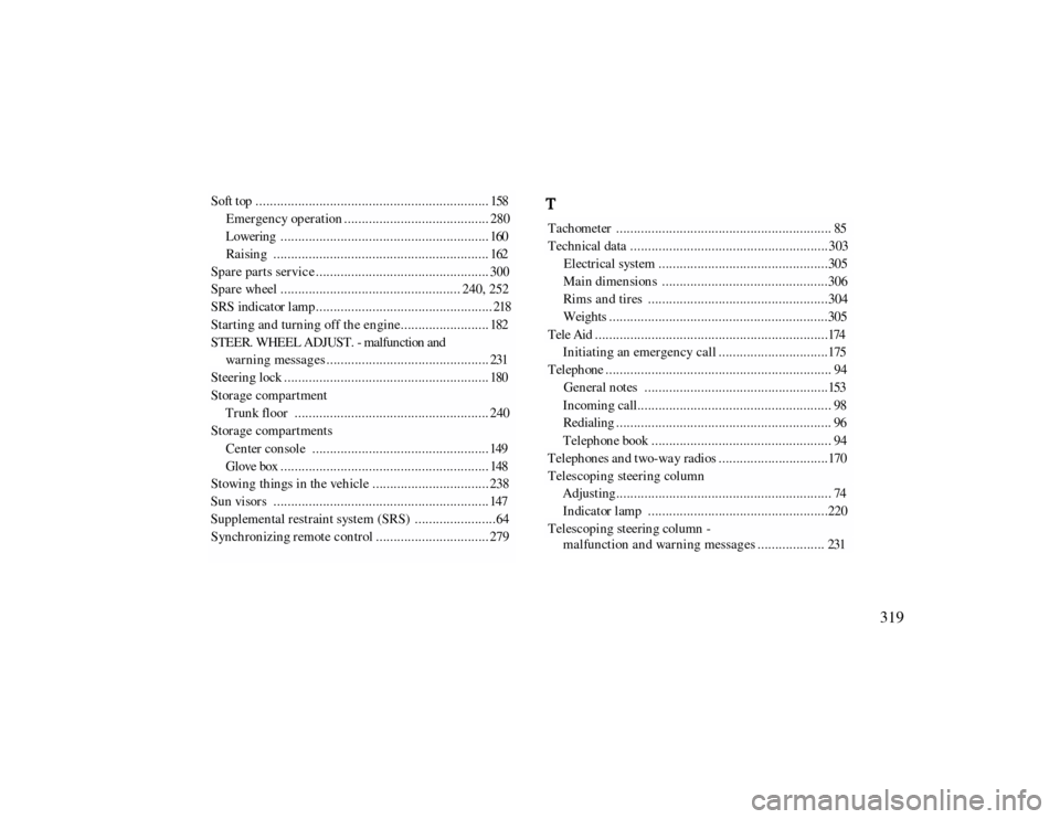
Soft top ..................................................................158
Emer gen cy op er ation ......................................... 280 L ower in g . . . . . . . . . . . . . . . . . . . . . . . . . . . . . . . . . . . . . . . . . . . . . . . . . . . . . . . . . . . 160 Raising ............................................................. 162
Spar e par ts ser vic e ................................................. 300 Spare wheel ................................................... 240, 252 S RS in d i ca t or l am p . . . . . . . . . . . . . . . . . . . . . . . . . . . . . . . . . . . . . . . . . . . . . . . . . . 218 S t a r t i n g an d t u r n in g o f f t h e e n g i n e . . . . . . . . . . . . . . . . . . . . . . . . . 182 STEER. WHEEL ADJUST. - malfunction and
wa r n i n g m e s s a g e s . . . . . . . . . . . . . . . . . . . . . . . . . . . . . . . . . . . . . . . . . . . . . . 231
S t ee r i n g l oc k . . . . . . . . . . . . . . . . . . . . . . . . . . . . . . . . . . . . . . . . . . . . . . . . . . . . . . . . . . 180 Storage compartment
Trunk floor ....................................................... 240
Storage compartments
C e n t er con sol e . . . . . . . . . . . . . . . . . . . . . . . . . . . . . . . . . . . . . . . . . . . . . . . . . . 149 Gl ove box . . . . . . . . . . . . . . . . . . . . . . . . . . . . . . . . . . . . . . . . . . . . . . . . . . . . . . . . . . . 148
Stowing th in gs in th e veh icle ................................. 238 S u n vi sor s . . . . . . . . . . . . . . . . . . . . . . . . . . . . . . . . . . . . . . . . . . . . . . . . . . . . . . . . . . . . . 147 Supplemental restraint system (SRS) .......................64 Syn ch ron izin g r emote c on tr ol ................................ 279
Tachometer ............................................................. 85 Technical data ........................................................303
Electrical system ................................................305 Main dimensions ...............................................306 Rims and tires ...................................................304 Weights ..............................................................305
T e l e Ai d . . . . . . . . . . . . . . . . . . . . . . . . . . . . . . . . . . . . . . . . . . . . . . . . . . . . . . . . . . . . . . . . . . 174
Initiating an emergency call ...............................175
Telephone ................................................................ 94
General notes ....................................................153 Incoming call....................................................... 98 Redialing ............................................................. 96 Telephone book ................................................... 94
Telephones and two-way radios ...............................170 Telescoping steering column
Adjusting............................................................. 74 In dicator lamp ...................................................220
Telescoping steering column -
m a l fu n ct i on a n d wa r n i n g m e s s a g e s . . . . . . . . . . . . . . . . . . . 231
319 T