Oil MERCEDES-BENZ CLS-Class 2016 W218 Owner's Guide
[x] Cancel search | Manufacturer: MERCEDES-BENZ, Model Year: 2016, Model line: CLS-Class, Model: MERCEDES-BENZ CLS-Class 2016 W218Pages: 342, PDF Size: 8.28 MB
Page 291 of 342

!Do not operate the tire inflation compressor
for longer than eight minutes at a time without
a break. It may otherwise overheat.
The tire inflation compressor can be operated
again once it has cooled down.
Comply with the manufacturer’s safety instruc-
tions on the sticker on the tire inflation com-
pressor.
Using the TIREFIT kit
XDo not remove any foreign objects which have
penetrated the tire, e.g. screws or nails.
XRemove the tire sealant bottle, the accompa-
nying TIREFIT sticker and the tire inflation
compressor from the stowage well under-
neath the trunk floor (
Ypage 286).
XAffix part :of the TIREFIT sticker to the
instrument cluster within the driver's field of
vision.
XAffix part ;of the TIREFIT sticker near the
valve on the wheel with the defective tire.
XPull connector ?with the cable and hose A
out of the tire inflation compressor housing.
XScrew hose Aonto flange Bof tire sealant
bottle :.
XPlace tire sealant bottle :head downwards
into recess ;of the tire inflation compres-
sor.
XRemove the cap from valve Con the faulty
tire.
XScrew filler hose Donto valve C.
XInsert connector ?into a 12 V socket
(Ypage 262) in your vehicle.
XTurn the SmartKey to position 1in the ignition
lock (Ypage 127).
XPress on and off switch =on the tire inflation
compressor to I.
The tire inflation compressor is switched on.
The tire is inflated.
First, tire sealant is pumped into the tire. The
pressure can briefly rise to approximately
500 kPa (5 bar/73 psi).
Do not switch off the tire inflation com-
pressor during this phase.
XLet the tire inflation compressor run for a
maximum of five minutes. The tire should then
have attained a pressure of at least 180 kPa
(1.8 bar/26 psi).
If a pressure of 180 kPa (1.8 bar/26 psi) has
been attained after five minutes, see "Tire pres-
sure reached" (
Ypage 290).
If a tire pressure of 180 kPa (1.8 bar/26 psi) has
not been attained after five minutes, see "Tire
pressure not reached" (
Ypage 290).
If tire sealant has escaped, clean it off affected
areas as quickly as possible. Use plain water if
possible.
If your clothes are soiled with tire sealant, have
them cleaned with perchloroethylene at a dry
cleaner as soon as possible.
Flat tire289
Breakdown assistance
Z
Page 321 of 342

Uniform Tire Quality Grading Standards
A uniform standard to grade the quality of tires
with regards to tread quality, tire traction and
temperature characteristics. The quality grad-
ing assessment is made by the manufacturer
following specifications from the U.S. govern-
ment. The ratings are molded into the sidewall ofthe tire.
Recommended tire pressures
The recommended tire pressure applies to the
tires mounted at the factory.
The Tire and Loading Information placard con-
tains the recommended tire pressures for cold
tires on a fully loaded vehicle and for the maxi-
mum permissible vehicle speed.
The tire pressure table contains the recommen-
ded pressures for cold tires for various operat-
ing conditions, i.e. differing load and speed con-
ditions.
Increased vehicle weight due to optional
equipment
The combined weight of all standard and
optional equipment available for the vehicle,
regardless of whether it is actually installed on
the vehicle or not.
Rim
This is the part of the wheel on which the tire is
mounted.
GAWR (Gross Axle Weight Rating)
The GAWR is the maximum gross axle weight
rating. The actual load on an axle must never
exceed the gross axle weight rating. The gross
axle weight rating can be found on the vehicle
identification plate on the B-pillar on the driver's
side.
Speed rating
The speed rating is part of the tire identification.
It specifies the speed range for which the tire is
approved.
GVW (Gross Vehicle Weight)
The gross vehicle weight includes the weight of
the vehicle including fuel, tools, the spare wheel,
accessories installed, occupants, luggage and
the drawbar noseweight, if applicable. The gross
vehicle weight must not exceed the gross vehi-
cle weight rating GVWR as specified on the vehi-
cle identification plate on the B-pillar on the
driver's side.
GVWR (Gross Vehicle Weight Rating)
The GVWR is the maximum permissible gross
weight of a fully loaded vehicle (the weight of the
vehicle including all accessories, occupants,
fuel, luggage and the drawbar n
oseweight, if
applicable). The gross vehicle weight rating is
specified on the vehicle identification plate on
the B-pillar on the driver's side.
Maximum loaded vehicle weight
The maximum weight is the sum of:
Rthe curb weight of the vehicle
Rthe weight of the accessories
Rthe load limit
Rthe weight of the factory installed optional
equipment
Kilopascal (kPa)
Metric unit for tire pressure. 6.9 kPa corre-
sponds to 1 psi. Another unit for tire pressure is
bar. 100 kilopascals (kPa) are the equivalent of
1 bar.
Load index
In addition to the load-bearing index, the load
index may also be imprinted on the sidewall of
the tire. This specifies the load-bearing capacity
more precisely.
Curb weight
The weight of a vehicle with standard equipment
including the maximum capacity of fuel, oil and
coolant. It also includes the air-conditioning sys-
tem and optional equipment if these are instal-
led in the vehicle, but does not include passen-
gers or luggage.
Maximum load rating
The maximum tire load is the maximum permis-
sible weight in kilograms or lbs for which a tire is
approved.
Maximum permissible tire pressure
Maximum permissible tire pressure for one tire.
Maximum load on one tire
Maximum load on one tire. This is calculated by dividing the maximum axle load of one axle by
two.
All about wheels and tires319
Wheels and tires
Z
Page 323 of 342

!On vehicles equipped with a tire pressure
monitor, electronic components are located
in the wheel.
Tire-mounting tools should not be used near
the valve. This could damage the electronic
components.
Only have tires changed at a qualified spe-
cialist workshop.
Always observe the instructions and safety
notes in the "Mounting a wheel" section
(
Ypage 321).
The wear patterns on the front and rear tires
differ, depending on the operating conditions.
Rotate the wheels before a clear wear pattern
has formed on the tires. Front tires typically
wear more on the shoulders and the rear tires in the center.
On vehicles that have the same size front and
rear wheels, you can rotate the wheels accord-
ing to the intervals in the tire manufacturer's
warranty book in your vehicle documents. If no
warranty book is available, the tires should be
rotated every 3,000 to 6,000 miles (5,000 to
10,000 km). Depending on tire wear, this may
be required earlier. Do not change the direction
of wheel rotation.
Clean the contact surfaces of the wheel and the
brake disc thoroughly every time a wheel is rota-
ted. Check the tire pressure and, if necessary,
restart the tire pressure loss warning system
(
Ypage 308) or the tire pressure monitor
(Ypage 311).
Direction of rotation
Tires with a specified direction of rotation have
additional benefits, e.g. if there is a risk of hydro- planing. These advantages can only be gained if
the tires are installed corresponding to the
direction of rotation.
An arrow on the sidewall of the tire indicates its
correct direction of rotation.
Storing wheels
Store wheels that are not being used in a cool,
dry and preferably dark place. Protect the tires
from oil, grease, gasoline and diesel.
Mounting a wheel
Preparing the vehicle
XStop the vehicle on solid, non-slippery and
level ground.
XApply the parking brake.
XBring the front wheels into the straight-ahead
position.
XShift the transmission to position P.
XVehicles with AIRMATIC: make sure that "nor-
mal" level is selected (Ypage 166).
XSwitch off the engine.
XRemove the SmartKey from the ignition lock.
or, on vehicles with KEYLESS‑ GO:
XOpen the driver's door.
The on-board electronics now have status 0.
This is the same as the SmartKey having been
removed.
XRemove the Start/Stop button from the igni-
tion lock (Ypage 127).
XIf included in the vehicle equipment, remove
the tire-change tool kit from the vehicle
(
Ypage 286).
XSafeguard the vehicle against rolling away.
Securing the vehicle to prevent it from
rolling away
If your vehicle is equipped with a wheel chock, it
can be found in the tire-change tool kit
(
Ypage 286).
The folding wheel chock is an additional safety
measure to prevent the vehicle from rolling
away, for example when changing a wheel.
XFold both plates upwards :.
XFold out lower plate;.
XGuide the lugs on the lower plate fully into the
openings in base plate =.
Changing a wheel321
Wheels and tires
Z
Page 324 of 342
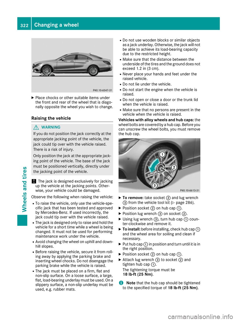
XPlace chocks or other suitable items under
the front and rear of the wheel that is diago-
nally opposite the wheel you wish to change.
Raising the vehicle
GWARNING
If you do not position the jack correctly at the
appropriate jacking point of the vehicle, the
jack could tip over with the vehicle raised.
There is a risk of injury.
Only position the jack at the appropriate jack-
ing point of the vehicle. The base of the jack
must be positioned vertically, directly under
the jacking point of the vehicle.
!The jack is designed exclusively for jacking
up the vehicle at the jacking points. Other-
wise, your vehicle could be damaged.
Observe the following when raising the vehicle:
RTo raise the vehicle, only use the vehicle-spe-
cific jack that has been tested and approved
by Mercedes-Benz. If used incorrectly, the
jack could tip over with the vehicle raised.
RThe jack is designed only to raise and hold the
vehicle for a short time while a wheel is being
changed. It must not be used for performing
maintenance work under the vehicle.
RAvoid changing the wheel on uphill and down-
hill slopes.
RBefore raising the vehicle, secure it from roll-
ing away by applying the parking brake and
inserting wheel chocks. Do not disengage the
parking brake while the vehicle is raised.
RThe jack must be placed on a firm, flat and
non-slip surface. On a loose surface, a large,
flat, load-bearing underlay must be used. On a
slippery surface, a non-slip underlay must be
used, e.g. rubber mats.
RDo not use wooden blocks or similar objects
as a jack underlay. Otherwise, the jack will not
be able to achieve its load-bearing capacity
due to the restricted height.
RMake sure that the distance between the
underside of the tires and the ground does not
exceed 1.2 in (3 cm).
RNever place your hands and feet under the
raised vehicle.
RDo not lie under the vehicle.
RDo not start the engine when the vehicle is
raised.
RDo not open or close a door or the trunk lid
when the vehicle is raised.
RMake sure that no persons are present in the
vehicle when the vehicle is raised.
Vehicles with alloy wheels and hub caps: the
wheel bolts are covered by a hub cap. Before you can unscrew the wheel bolts, you must remove
the hub cap.
XTo remove: take socket;and lug wrench
= from the vehicle tool kit (Ypage 286).
XPosition socket ;on hub cap :.
XPosition lug wrench =on socket ;.
XUsing lug wrench =, turn hub cap:coun-
ter-clockwise and remove it.
XTo install: before installing, check hub cap :
and the wheel area for soiling and clean if
necessary.
XPut hub cap :in position and turn until it is in
the right position.
XPosition socket ;on hub cap :.
XAttach lug wrench =to socket ;and
tighten hub cap :.
The tightening torque must be
18 lb-ft (25 Nm).
iNote that the hub cap should be tightened
to the specified torque of 18 lb-ft (25 Nm).
322Changing a wheel
Wheels and tires
Page 326 of 342
Mounting a new wheel
GWARNING
Oiled or greased wheel bolts or damaged
wheel bolts/hub threads can cause the wheel bolts to come loose. As a result, you could
lose a wheel while driving. There is a risk of
accident.
Never oil or grease wheel bolts. In the event of
damage to the threads, contact a qualified
specialist workshop immediately. Have the
damaged wheel bolts or hub threads
replaced/renewed. Do not continue driving.
GWARNING
If you tighten the wheel bolts or wheel nuts
when the vehicle is raised, the jack could tip
over. There is a risk of injury.
Only tighten the wheel bolts or wheel nuts
when the vehicle is on the ground.
Always pay attention to the instructions and
safety notes in the "Changing a wheel" section
(
Ypage 320).
Only use wheel bolts that have been designed
for the wheel and the vehicle. For safety rea-
sons, Mercedes-Benz recommends that you
only use wheel bolts which have been approved for Mercedes-Benz vehicles and the respective
wheel.
!Mercedes-AMG vehicles with ceramic-
brake disc: during removal and repositioning
of the wheel, the wheel rim can strike the
ceramic-brake disc and damage it. Therefore,
you should proceed carefully and get a sec-
ond person assist to you. Alternatively, you
can use a second alignment bolt.
!To prevent damage to the paintwork, hold
the wheel securely against the wheel hub
while screwing in the first wheel bolt.
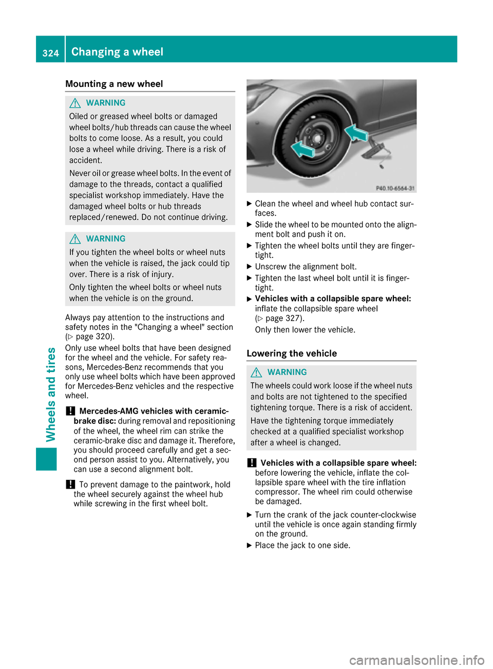
XClean the wheel and wheel hub contact sur-
faces.
XSlide the wheel to be mounted onto the align-
ment bolt and push it on.
XTighten the wheel bolts until they are finger-
tight.
XUnscrew the alignment bolt.
XTighten the last wheel bolt until it is finger-
tight.
XVehicles with a collapsible spare wheel:
inflate the collapsible spare wheel
(
Ypage 327).
Only then lower the vehicle.
Lowering the vehicle
GWARNING
The wheels could work loose if the wheel nuts and bolts are not tightened to the specified
tightening torque. There is a risk of accident.
Have the tightening torque immediately
checked at a qualified specialist workshop
after a wheel is changed.
!Vehicles with a collapsible spare wheel:
before lowering the vehicle, inflate the col-
lapsible spare wheel with the tire inflation
compressor. The wheel rim could otherwise
be damaged.
XTurn the crank of the jack counter-clockwise
until the vehicle is once again standing firmly
on the ground.
XPlace the jack to one side.
324Changing a wheel
Wheels and tires
Page 333 of 342

from the data shown here. You can find the
data applicable to your vehicle on the vehicle
identification plate.
Vehicle identification number (VIN)
XSlide the right-hand front seat to its rearmost
position.
XFold floor covering:upwards.
You will see VIN ;.
Engine number
:Emission control information plate, includ-
ing the certification of both federal and Cali-
fornian emissions standards
;Engine number (stamped into the crank-
case)
=VIN (on the lower edge of the windshield)
Service products and filling capaci-
ties
Important safety notes
GWARNING
Service products may be poisonous and haz-
ardous to health. There is a risk of injury.
Comply with instructions on the use, storage
and disposal of service products on the labels
of the respective original containers. Always
store service products sealed in their original
containers. Always keep service products out
of the reach of children.
HEnvironmental note
Dispose of service products in an environ-
mentally responsible manner.
Service products include the following:
RFuels
RLubricants (e.g. engine oil, transmission oil)
RCoolant
RBrake fluid
RWindshield washer fluid
RClimate control system refrigerant
Components and service products must be
matched. Only use products recommended by
Mercedes-Benz. Damage which is caused by the
use of products which have not been recom-
mended is not covered by the Mercedes-Benz
warranty or goodwill gestures. They are listed in
this Mercedes-Benz Operator's Manual in the
appropriate section.
Information on tested and approved products
can be obtained at an authorized Mercedes-
Benz Center or on the Internet at
http://bevo.mercedes-benz.com.
You can recognize service products approved by
Mercedes-Benz by the following inscription on
the containers:
RMB-Freigabe (e.g. MB-Freigabe 229.51)
RMB-Approval (e.g. MB-Approval 229.51)
Other designations or recommendations indi-
cate a level of quality or a specification in
accordance with an MB Sheet Number (e.g. MB 229.5). They have not necessarily been
approved by Mercedes-Benz.
Service products and filling capacities331
Technical data
Z
Page 335 of 342

RGasoline with metalliferous additives
RDiesel
Do not mix such fuels with the fuel recom-
mended for your vehicle.
!To ensure the longevity and full perform-
ance of the engine, only premium-grade
unleaded gasoline must be used.
If standard unleaded gasoline is unavailable
and you have to refuel with unleaded gasoline
of a lower grade, observe the following pre-
cautions:
ROnly fill the fuel tank to half full with regular
unleaded gasoline and fill the rest with pre-
mium-grade unleaded gasoline as soon as
possible.
RDo not drive at the maximum speed.
RAvoid sudden acceleration and engine
speeds over 3,000 rpm.
You will usually find information about the fuel
grade on the pump. If you cannot find the label
on the pump, ask the staff for assistance.
iFor further information, consult a qualified
specialist workshop or visit
http://www.mbusa.com (USA only).
As a temporary measure, if the recommended
fuel is not available, you may also use regular
unleaded gasoline with an octane rating of
87 AKI/91 RON. This may reduce engine per-
formance and increase fuel consumption. Avoid
driving at full throttle and sudden acceleration.
Never refuel using fuel with a lower AKI.
Information on refueling (
Ypage 144).
Additives
iIn some countries, the available gasoline
may not be sufficiently low in sulfur. This fuel
can temporarily produce unpleasant odors,
especially on short journeys. As soon as sul-
f
ur-free fuel (sulfur content <10 ppm) is used
for refueling, the odors are reduced.
Engine oil
General notes
!Never use engine oil or an oil filter of a spec-
ification other than is necessary to fulfill the
prescribed service intervals. Do not change
the engine oil or oil filter in order to achieve
longer replacement intervals than those pre-
scribed. You could otherwise cause engine
damage or damage to the exhaust gas after-
treatment.
Follow the instructions in the service interval display regarding the oil change. Otherwise,
you may damage the engine and the exhaust
gas aftertreatment.
When handling engine oil, observe the important
safety notes on service products (
Ypage 331).
The engine oils are matched to the performance
of Mercedes-Benz engines and service intervals.
You should therefore only use engine oils and oil
filters that are approved for vehicles with main- tenance systems.
For a list of approved engine oils and oil filters,
consult an authorized Mercedes-Benz Center.
Or visit the website
http://bevo.mercedes-benz.com.
The table shows which engine oils have been
approved for your vehicle.
ModelMB-Freigabe or MB-
Approval
All models229.5
Use only SAE 0W-40 or SAE 5W-40 engine oils
for Mercedes‑AMG vehicles.
iMB approval is indicated on the oil contain-
ers.
Service products and filling capacities333
Technical data
Z
Page 336 of 342
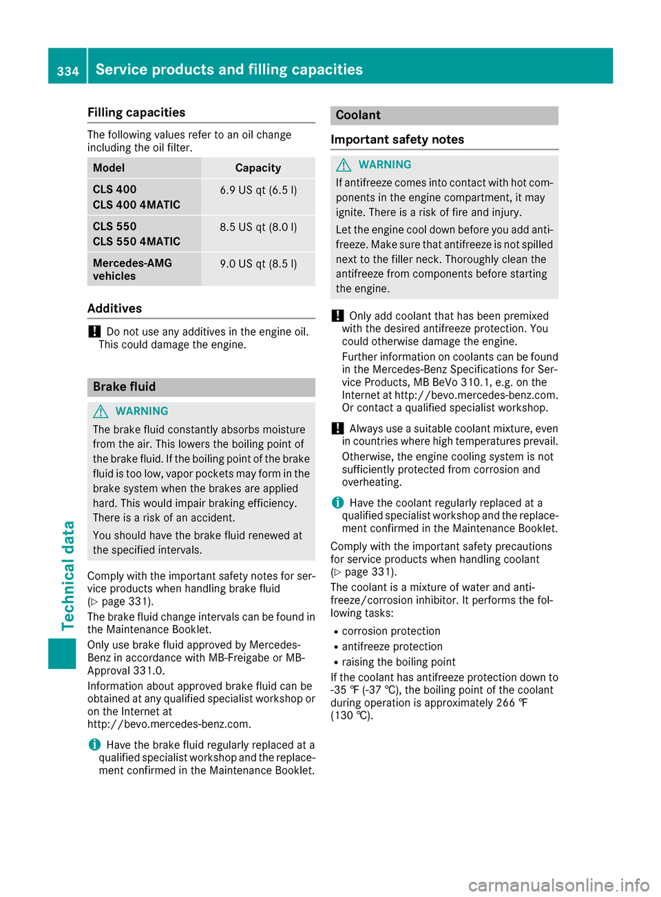
Filling capacities
The followingvalue srefer to an oil chang e
includin gth eoil filter.
ModelCapacit y
CLS 400
CLS 400 4MATIC6.9US qt (6.5l)
CLS 550
CLS 550 4MATIC8.5 US qt (8.0 l)
Mercedes‑AMG
vehicles9.0 US qt (8.5l)
Additives
!Do not use any additives in the engine oil.
This could damage the engine.
Brake fluid
GWARNING
The brake fluid constantly absorbs moisture
from the air. This lowers the boiling point of
the brake fluid. If the boiling point of the brake
fluid is too low, vapor pockets may form in the
brake system when the brakes are applied
hard. This would impair braking efficiency.
There is a risk of an accident.
You should have the brake fluid renewed at
the specified intervals.
Comply with the important safety notes for ser-
vice products when handling brake fluid
(
Ypage 331).
The brake fluid change intervals can be found in
the Maintenance Booklet.
Only use brake fluid approved by Mercedes-
Benz in accordance with MB-Freigabe or MB-
Approval 331.0.
Information about approved brake fluid can be
obtained at any qualified specialist workshop or on the Internet at
http://bevo.mercedes-benz.co m.
iHave the brake fluid regularly replaced at a
qualified specialist workshop and the replace-
ment confirmed in the Maintenance Booklet.
Coolant
Important safety notes
GWARNING
If antifreeze comes into contact with hot com- ponents in the engine compartment, it may
ignite. There is a risk of fire and injury.
Let the engine cool down before you add anti-
freeze. Make sure that antifreeze is not spilled
next to the filler neck. Thoroughly clean the
antifreeze from components before starting
the engine.
!Only add coolant that has been premixed
with the desired antifreeze protection. You
could otherwise damage the engine.
Further information on coolants can be found
in the Mercedes-Benz Specifications for Ser-
vice Products, MB BeVo 310.1, e.g. on the
Internet at http://bevo.mercedes-benz.com.
Or contact a qualified specialist workshop.
!Always use a suitable coolant mixture, even
in countries where high temperatures prevail.
Otherwise, the engine cooling system is not
sufficiently protected from corrosion and
overheating.
iHave the coolant regularly replaced at a
qualified specialist workshop and the replace-
ment confirmed in the Maintenance Booklet.
Comply with the important safety precautions
for service products when handling coolant
(
Ypage 331).
The coolant is a mixture of water and anti-
freeze/corrosion inhibitor. It performs the fol-
lowing tasks:
Rcorrosion protection
Rantifreeze protection
Rraising the boiling point
If the coolant has antifreeze protection down to -35 ‡ (-37 †), the boiling point of the coolant
during operation is approximately 266 ‡
(130 †).
334Service products and filling capacities
Technical data
Page 337 of 342

The antifreeze concentrate/corrosion inhibitor
concentration in the engine cooling system
should:
Rbe at least 50%. This will protect the engine
cooling system against freezing down to
approximately -35 ‡ (-37 †).
Rnot exceed 55% (antifreeze protection down
to -49‡[-45 †]). Otherwise, heat will not be
dissipated as effectively.
Mercedes-Benz recommends an antifreeze/
corrosion inhibitor concentrate in accordance
with MB Specifications for Service Products
310.1.
iWhen the vehicle is first delivered, it is filled
with a coolant mixture that ensures adequate
antifreeze and corrosion protection.
iThe coolant is checked with every mainte-
nance interval at a qualified specialist work-
shop.
Filling capacities
ModelCapacity
CLS 400
CLS 400 4MATICApprox. 10.9 US qt (10.3l)
CLS 550
CLS 550 4MATICApprox. 11.5 US qt (10.9l)
Mercedes‑AMG
vehiclesApprox. 11.4 US qt
(10.8l)
Windshield washer system
Important safety notes
GWARNING
Windshield washer concentrate could ignite if it comes into contact with hot engine compo-
nents or the exhaust system. There is a risk of
fire and injury.
Make sure that no windshield washer con-
centrate is spilled next to the filler neck.
!Only use washer fluid that is suitable for
plastic lamp lenses, e.g. MB SummerFit or MB WinterFit. Unsuitable washer fluid could dam-
age the plastic lenses of the headlamps.
!Only MB SummerFit and MB WinterFit
washer fluid should be mixed together. The
spray nozzles may otherwise become
blocked.
Do not use distilled or de-ionised water, other-
wise, the level sensor may give a false reading.
When handling washer fluid, observe the impor-
tant safety notes on service products
(
Ypage 331).
At temperatures above freezing:
XFill the washer fluid reservoir with a mixture of
water and windshield washer fluid, e.g. MB
SummerFit.
Add 1 part MB SummerFit to 100 parts water.
At temperatures below freezing:
XFill the washer fluid reservoir with a mixture of
water and washer fluid, e.g. MB WinterFit.
For the correct mixing ratio refer to the infor-
mation on the antifreeze reservoir.
iAdd windshield washer fluid, e.g. MB Sum-
merFit or MB WinterFit, to the washer fluid all
year round.
Climate control system refrigerant
Important safety notes
The climate control system of your vehicle is fil-
led with refrigerant R ‑134a.
The instruction label regarding the refrigerant
type used can be found on the radiator cross
member.
!Only the refrigerant R ‑134a and the PAG oil
approved by Mercedes-Benz may be used.
The approved PAG oil may not be mixed with
any other PAG oil that is not approved for
R-134a refrigerant. Otherwise, the climate
control system may be damaged.
Service work, such as topping up refrigerant or
replacing components, may only be carried out
by a qualified specialist workshop. All applicable
regulations must be adhered to, SAE standard
J639 included.
Always have work on the climate control system
carried out at a qualified specialist workshop.
Service products and filling capacities335
Technical data
Z
Page 338 of 342
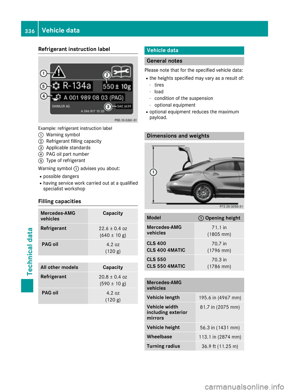
Refrigerant instruction label
Example: refrigerant instruction label
:
Warning symbol
;Refrigerant filling capacity
=Applicable standards
?PAG oil part number
AType of refrigerant
Warning symbol :advises you about:
Rpossible dangers
Rhaving service work carried out at a qualified
specialist workshop
Filling capacities
Mercedes ‑AMG
vehiclesCapacity
Refrigerant22.6 ± 0.4 oz
(640 ± 10 g)
PAG oil4.2 oz
(120 g)
All other modelsCapacity
Refrigerant20.8 ± 0.4 oz (590 ± 10 g)
PAG oil4.2 oz
(120 g)
Vehicle data
General notes
Please note that for the specified vehicle data:
Rthe heights specified may vary as a result of:
-tires
-load
-condition of the suspension
-optional equipment
Roptional equipment reduces the maximum
payload.
Dimensions and weights
Model:Opening height
Mercedes‑AMG
vehicles71.1 in
(1805 mm)
CLS 400
CLS 400 4MATIC70.7 in
(1796 mm)
CLS 550
CLS 550 4MATIC70.3 in
(1786 mm)
Mercedes‑AMG
vehicles
Vehicle length195.6 in (4967 mm)
Vehicle width
including exterior
mirrors81.7 in (2075 mm)
Vehicle height56.3 in (1431 mm)
Wheelbase113.1 in (2874 mm)
Turning radius36.9 ft (11.25 m)
336Vehicle data
Technical data