warning MERCEDES-BENZ CLS COUPE 2011 User Guide
[x] Cancel search | Manufacturer: MERCEDES-BENZ, Model Year: 2011, Model line: CLS COUPE, Model: MERCEDES-BENZ CLS COUPE 2011Pages: 337, PDF Size: 7.37 MB
Page 18 of 337
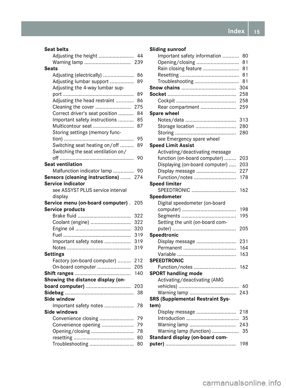
Seat belts
Adjusting the height .........................44
Warning lamp ................................. 239
Seats
Adjusting (electrically) .....................86
Adjusting lumba rsuppor t................ 89
Adjusting the 4-way lumba rsup-
por t.................................................. 89
Adjusting the head restraint ............86
Cleaning the cover .........................275
Correct driver's seat position ........... 84
Important safety instructions ...........85
Multicontour sea t............................ 87
Storing settings (memory func-
tion) ................................................. 95
Switching sea theating on/off .........89
Switching the sea tventilation on/
off .................................................... 90
Seat ventilation
Malfunction indicator lamp ..............90
Sensors (cleaning instructions) .......274
Service indicator see ASSYST PLUS service interval
display
Service menu (on-board computer) .205
Service products Brake fluid ..................................... 322
Coolant (engine) ............................ 322
Engine oil ....................................... 320
Fuel ................................................ 319
Important safety notes ..................319
Notes ............................................. 319
Settings
Factory (on-board computer) .........212
On-board computer .......................205
Shift ranges ....................................... 140
Showing the distance display (on-
board computer) ............................... 203
Sidebag ................................................ 38
Side window Important safety notes ....................78
Side windows
Convenience closing ........................79
Convenience opening ......................79
Opening/closing .............................. 78
resetting .......................................... 80
Troubleshooting ............................... 80Sliding sunroof
Important safety information ...........80
Opening/closing .............................. 81
Rain closing feature .........................81
Resetting ......................................... 81
Troubleshooting ............................... 81
Snow chains ...................................... 304
Socket ................................................ 258
Cockpi t.......................................... 258
Rea rcompartmen t......................... 259
Spare wheel
Notes/data .................................... 313
Storage location ............................ 280
Storing ........................................... 280
see Emergency spare wheel
Spee dLimit Assist
Activating/deactivating message
function (on-board computer )........ 203
Displaying (on-board computer) ..... 203
Display message ............................ 227
Function/notes ............................. 178
Spee dlimiter
SPEEDTRONIC ............................... 162
Speedometer
Digital speedometer (on-board
computer) ...................................... 198
Segments ...................................... 195
Setting the unit (on-board com-
puter) ............................................. 205
Speedtronic
Display message ............................ 231
Permanent ..................................... 164
Variabl e......................................... 163
SPEEDTRONIC
Function/notes ............................. 162
SPORT handling mode
Activating/deactivating (AMG
vehicles) .......................................... 60
Warning lamp ................................. 243
SRS (Supplemental Restraint Sys-
tem)
Display message ............................ 218
Introduction ..................................... 35
Warning lamp ................................. 243
Warning lamp (function) ................... 35
Standard display (on-board com-
puter) ................................................. .198 Index
15
Page 20 of 337
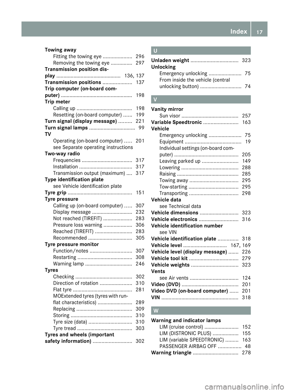
Towing away
Fitting the towing ey e.................... 296
Removing the towing eye. ..............297
Transmission position dis-
play ............................................. 136, 137
Transmission positions ....................137
Trip computer (on-board com-
puter) ................................................. .198
Trip meter Calling up ....................................... 198
Resetting (on-board computer) ......199
Turn signal (display message) .........221
Turn signal lamps ................................ 99
TV Operating (on-board computer) .....201
see Separate operating instructions
Two-way radio
Frequencies ................................... 317
Installatio n..................................... 317
Transmission output (maximum) .... 317
Type identification plate
see Vehicle identification plate
Tyre grip ............................................. 151
Tyre pressure Calling up (on-board computer) .....307
Display message ............................ 232
Not reached (TIREFIT) ....................283
Pressure loss warning ....................306
Reached (TIREFIT) ..........................283
Recommended ............................... 305
Tyre pressure monitor
Function/notes ............................. 307
Restarting ...................................... 308
Warning lamp ................................. 246
Tyres
Checking ........................................ 302
Directio nofrotation ...................... 310
Flat tyre ......................................... 281
MOExtended tyres (tyre swith run-
flat characteristics) ........................289
Replacing ....................................... 309
Storing ........................................... 310
Tyr esize (data) .............................. 310
Tyr etread ...................................... 303
Tyres and wheels (important
safety information) ...........................302 U
Unladen weight ................................. 323
Unlocking Emergency unlocking .......................75
From inside the vehicle (central
unlocking button) ............................. 74 V
Vanity mirror Sun visor ........................................ 257
Variable Speedtronic ........................163
Vehicle Emergency unlocking .......................75
Equipment ....................................... 19
Individual settings (on-board com-
puter) ............................................. 205
Leaving parked up .........................149
Lowering ........................................ 288
Raising ........................................... 285
Towing away .................................. 295
Tow-starting ................................... 295
Transporting .................................. 298
Vehicle data
see Technical data
Vehicle dimensions ...........................323
Vehicle electronics ...........................316
Vehicle identification number see VIN
Vehicle identification plate ..............318
Vehicle level .............................. 167, 169
Vehicle level (display message) .......226
Vehicle tool kit .................................. 279
Vehicle weights ................................. 323
Vents see Air vents .................................. 124
Video (DVD) ........................................ 201
Video DVD (on-board computer) ......201
VIN ...................................................... 318 W
Warning and indicator lamps LIM (cruise control) ........................ 152
LIM (DISTRONIC PLUS) ..................155
LIM (variable SPEEDTRONIC) .........163
PASSENGER AIRBAG OFF ................48
Warning triangle ................................ 278 Index
17
Page 24 of 337
Inform Mercedes-Benz as soon as possible
abouta ny change in address or vehicle own-
ership. Correc
tuse
Observe the following information when using
your vehicle:
R the safety notes in this manual
R the "Technical data” section in this manual
R national road traffic regulations
R national road traffic licensing regulations G
Risk of injury
Various warning stickers are affixed to your
vehicle. Their purpose is to draw your atten-
tion, and the attention of others, to various
dangers. Therefore, do not remove any warn-
ing stickers unless the sticker clearly states
that you may do so.
If you remove the warning stickers, you or
others could be injured by failing to recognise
certain dangers. Implied warranty
! Follow the instructions in this manual
about the proper operation of your vehicle
as well as about possible vehicle damage.
Damage to your vehicle that arises from
culpable contraventions against these
instructions are not covered either by
Mercedes-Benz implied warranty or by the
New or Used-Vehicle Warranty of
Daimler AG. Data stored in the vehicle
Fault data
Components critical for vehicle operation are
equipped with fault data memories as stand-
ard. There are also data storage devices
which record the technical reactions of vehi-
cle components to certain driving situations (e.g. airbag deployment or ESP
®
interven-
tion).
This data is used exclusively to:
R assist in the rectification of faults and
defects
R help Mercedes-Benz optimise and develop
vehicle functions
The data cannot be used to trace the vehicle's
movements.
When your vehicle is serviced by Mercedes-
Benz, this technical information can be read
out from the fault memory. This is performed
by authorised employees of the Mercedes-
Benz service network using special diagnos-
tic computers.
After a fault has been rectified, the informa-
tion is deleted from the memory. Other mem-
ory data is constantly overwritten. Other devices that store data
Depending on the equipment level, your vehi-
cle may feature communications and/or
entertainment systems (e.g. navigation devi-
ces, telephone systems). These allow you to
save and edit data required for the operation
of the respective device.
Further information on operation (e.g. on
deleting data) can be found in the separate
operating instructions. Introduction
21 Z
Page 27 of 337
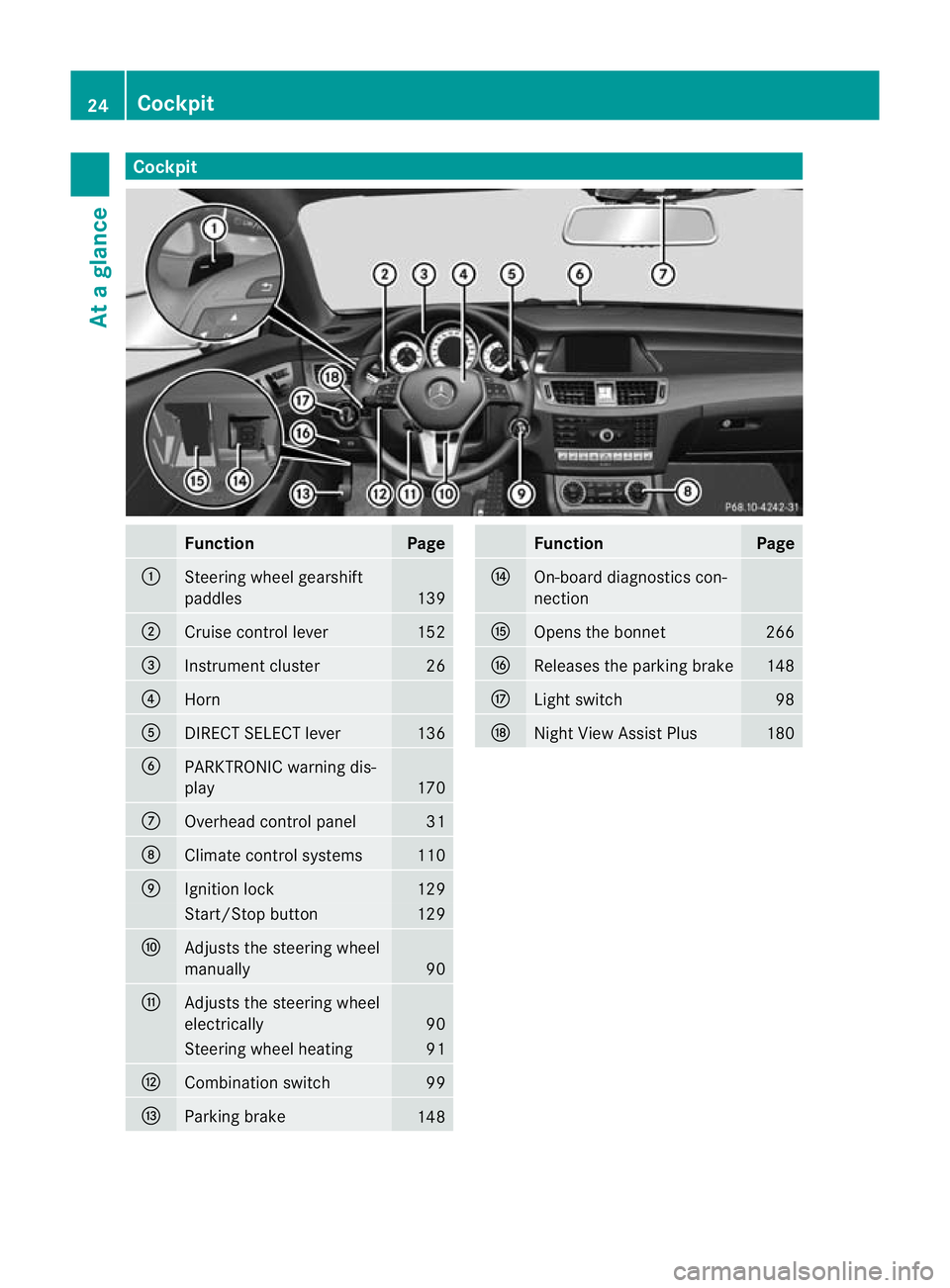
Cockpit
Function Page
:
Steering wheel gearshift
paddles
139
;
Cruise control lever 152
=
Instrument cluster 26
?
Horn
A
DIRECT SELECT lever 136
B
PARKTRONIC warning dis-
play
170
C
Overhead control panel 31
D
Climate control systems 110
E
Ignition lock 129
Start/Stop button 129
F
Adjusts the steering wheel
manually
90
G
Adjusts the steering wheel
electrically
90
Steering wheel heating 91
H
Combination switch 99
I
Parking brake
148 Function Page
J
On-board diagnostics con-
nection K
Opens the bonnet 266
L
Releases the parking brake 148
M
Ligh
tswitch 98
N
Night View Assist Plus 18024
CockpitAt a glance
Page 28 of 337
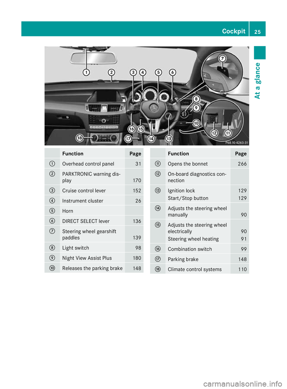
Function Page
:
Overhead control panel 31
;
PARKTRONIC warning dis-
play
170
=
Cruise control lever 152
?
Instrument cluster 26
A
Horn
B
DIRECT SELECT lever 136
C
Steering wheel gearshift
paddles
139
D
Ligh
tswitch 98
E
Nigh
tView Assist Plus 180
F
Releases the parking brake
148 Function Page
G
Opens the bonnet 266
H
On-board diagnostics con-
nection
I
Ignition lock 129
Start/Stop button 129
J
Adjusts the steering wheel
manually
90
K
Adjusts the steering wheel
electrically
90
Steering wheel heating 91
L
Combination switch 99
M
Parking brake 148
N
Climate control systems 110Cockpit
25At a glance
Page 31 of 337
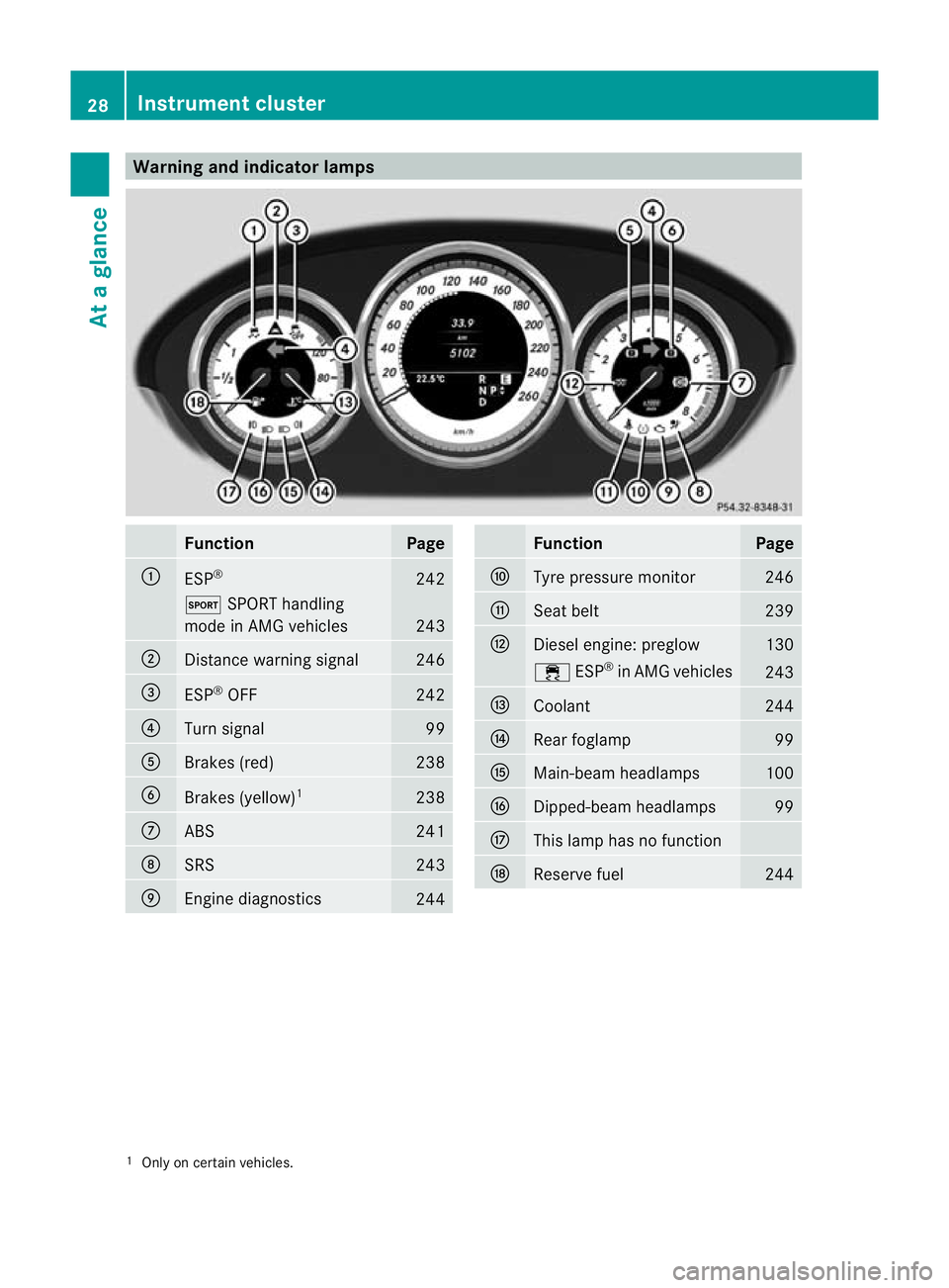
Warning and indicator lamps
Function Page
:
ESP
® 242
M
SPORT handling
mode in AMG vehicles 243
;
Distance warning signal 246
=
ESP
®
OFF 242
?
Turn signal 99
A
Brakes (red) 238
B
Brakes (yellow)
1 238
C
ABS 241
D
SRS 243
E
Engine diagnostics
244 Function Page
F
Tyre pressure monitor 246
G
Seat belt 239
H
Diesel engine: preglow 130
÷
ESP®
in AMG vehicles 243
I
Coolant 244
J
Rea
rfoglamp 99
K
Main-beam headlamps 100
L
Dipped-beam headlamps 99
M
This lamp has no function
N
Reserve fuel 244
1
Only on certain vehicles. 28
Instrument clusterAt a glance
Page 33 of 337
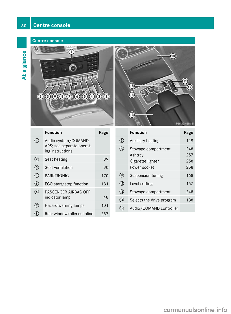
Centre console
Function Page
:
Audio system/COMAND
APS; see separate operat-
ing instructions
;
Seat heating 89
=
Seat ventilation 90
?
PARKTRONIC 170
A
ECO start/stop function 131
B
PASSENGER AIRBAG OFF
indicator lamp
48
C
Hazard warning lamps 101
D
Rear window roller sunblind
257 Function Page
E
Auxiliary heating 119
F
Stowage compartment 248
Ashtray 257
Cigarette lighter 258
Power socket 258
G
Suspension tuning 168
H
Level setting 167
I
Stowage compartment 248
J
Selects the drive program 138
K
Audio/COMAND controller30
Centre consoleAt a glance
Page 38 of 337
Airbags and belt tensioners could fail to
deploy or be triggered in an accident despite
the deceleratio nforce being sufficient to trig-
ger the systems, or could be triggered unin-
tentionally. For this reason, never make any
modifications to the restraint systems.
Therefore, you must not tamper with elec-
tronic components or their software. SRS (Supplemental Restraint System)
Introduction SRS reduces the risk of occupants coming
into contact with the vehicle's interior in the
event of an accident. It can also reduce the
effect of the forces to which occupants are
subjected during an accident.
SRS consists of:
R the 6 SRS warning lamp
R airbags
R airbag control unit (with crash sensors)
R belt tensioners
R belt force limiters
SRS warning lamp SRS functions are checked regularly when
you switch on the ignition and when the
engine is running. Therefore, malfunctions
can be detected in good time.
The 6 SRS warning lamp in the instrument
cluster lights up when the ignition is switched
on. It goes out no later than a few seconds
after the engine is started. G
Risk of injury
If SRS is malfunctioning, individual systems
may be activated unintentionally or may not
be triggered in the event of an accident with
a high rate of vehicle deceleration. A malfunction has occurred if:
R
the 6 SRS warning lamp does not light
up when the ignition is switched on.
R the engine is running and the 6SRS
warning lamp does not go out after a few
seconds.
R the engine is running and the 6SRS
warning lamp lights up again.
In this case, have SRS checked immediately
at a qualified specialist workshop. Mercedes-
Benz recommends that you use a Mercedes-
Benz Service Centre for this purpose.
In particular, work relevant to safety or on
safety-related systems must be carried out at
a qualified specialist workshop.
Triggering of belt tensioners, belt force
limiters and airbags During the first stage of a collision, the airbag
control unit evaluates important physical
data relating to vehicle deceleration or accel-
eration, such as
R
duration
R direction
R magnitude
Based on the evaluation of this data, the air-
bag control unit pre-emptively triggers the
belt tensioners in the first stage.
i The front belt tensioners can only be trig-
gered if the seat belt tongues on the front
seats are correctly engaged in the seat belt
buckles.
If there is an even higher rate of vehicle decel-
eration or acceleration in a longitudinal direc-
tion, the front airbags are also deployed.
Your vehicle has adaptive, two-stage front air-
bags. The airbag control unit evaluates vehi-
cle deceleration or acceleration in the event
of a collision. When the first deployment
threshold is reached, the front airbag is filled
with enough propellant gas to reduce the risk
of injuries. The front airbag is fully deployed
if a second deployment threshold is exceeded
within a few milliseconds. Occupant safety
35Safety Z
Page 39 of 337
The belt tensioner and airbag triggering
thresholds are variable and are adapted to the
rate of deceleration or acceleration of the
vehicle. This process is pre-emptive in nature.
The triggering process must take place in
good time at the start of the collision.
i Not all airbags are deployed in an acci-
dent. The different airbag systems work
independently of each other.
How the airbag system works is deter-
mined by the severity of the accident detec-
ted, especially the vehicle deceleration or
acceleration, and the apparent type of acci-
dent:
R head-on collision
R side impact
R overturn
The rate of vehicle deceleration or accelera-
tion and the direction of the force are essen-
tially determined by:
R the distribution of forces during the colli-
sion
R the collision angle
R the deformation characteristics of the vehi-
cle
R the characteristics of the object with which
the vehicle has collided
Factors which can only be seen and measured
after a collision has occurred do not play a
decisive role in the deployment of an airbag
nor do they provide an indication of airbag
deployment.
The vehicle may be deformed significantly,
e.g. the bonnet or the wing, without an airbag
being deployed. This is the case if only parts
which are relatively easily deformed are affec-
ted and the deployment threshold is not
reached. Conversely, airbags may be
deployed even though the vehicle suffers only
minor deformation .This is the case if, for
example, very rigid vehicle parts such as lon-
gitudinal body members are hit and sufficient
deceleration occurs as a result. Airbags
Important safety notes Airbag deployment slows down and restricts
the movement of the vehicle occupant.
If the airbags are deployed, you will hear a
bang, and a small amount of powder may also
be released. Only in rare cases will the bang
affect your hearing. The powder that is
released generally does not constitute a
health hazard. The 6SRS warning lamp
lights up.
The airbag installation locations are identified
by the AIRBAG symbol. G
Risk of injury
Airbags provide additional protection; they
are not, however, a substitute for seat belts.
Observe the following notes to reduce the risk
of serious or even fatal injury caused by airbag
deployment:
R All vehicle occupants –inparticular, preg-
nant women – must wear their seat belt
correctly at all times and lean back against
the backrest, which should be positioned
as close to the vertical as possible. The
head restraint must support the back of the
head at about eye level.
R Always secure childre nless than 1.50mt all
and unde r12years of age in suitable child
restraint systems.
R All vehicle occupants must select a seat
position that is as far away from the airbag
as possible. The driver's seat position must
allow the vehicle to be driven safely. The
driver's chest should be as far away from
the centre of the driver's airbag cover as
possible.
R Move the front-passenger seat as far back
as possible. This is especially important if
you have secured a child in a child restraint
system on the front-passenger seat.
R Vehicle occupants –inparticular, children
–m ust no tlean their heads into the area of
the window in which the sidebag/window-
bag is deployed. 36
Occupant safetySafety
Page 47 of 337
The belt strap is tightened slightly when:
R you engage the belt tongue in the belt
buckle and you then turn the key to position
2in the ignition lock.
R the key is in position 2in the ignition lock
and you then engage the belt tongue in the
buckle.
The seat-belt adjustmen twill apply a certain
tightening force if any slack is detected
between the occupant and the seat belt. Do
not hold on to the seat belt tightly while it is
adjusting. You can switch the seat-belt
adjustment on and off in the on-board com-
puter (Y page 211).
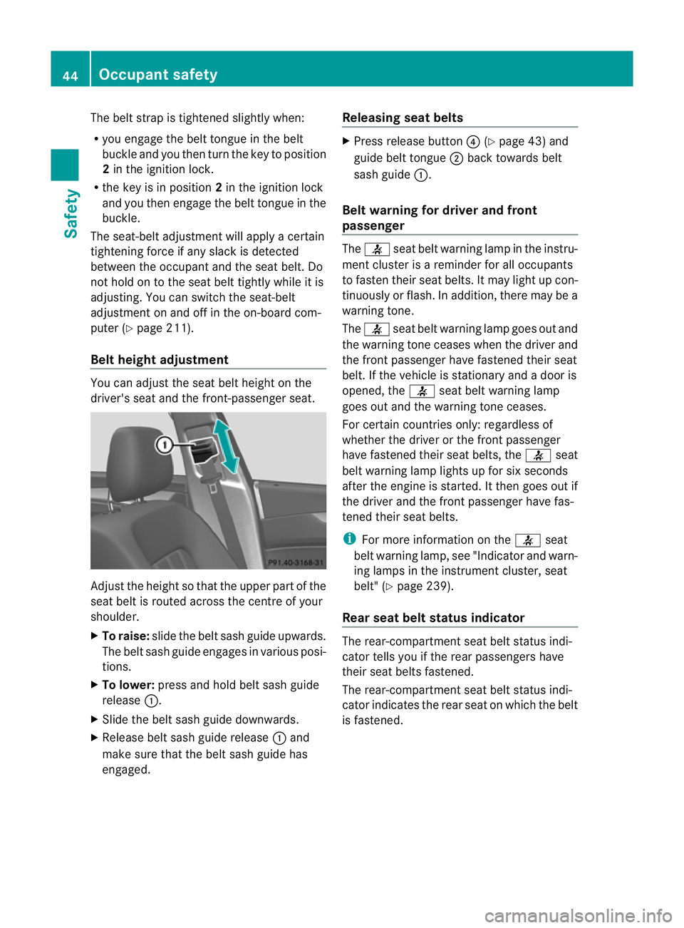
Belt height adjustment You can adjust the seat belt height on the
driver's seat and the front-passenger seat.
Adjust the height so that the upper part of the
seat belt is routed across the centre of your
shoulder.
X
To raise: slide the belt sash guide upwards.
The belt sash guide engages in various posi-
tions.
X To lower: press and hold belt sash guide
release :.
X Slide the belt sash guide downwards.
X Release belt sash guide release :and
make sure that the belt sash guide has
engaged. Releasing seat belts X
Press release button ?(Ypage 43) and
guide belt tongue ;back towards belt
sash guide :.
Belt warning for driver and front
passenger The
7 seat belt warning lamp in the instru-
ment cluster is a reminder for all occupants
to fasten their seat belts .Itmay light up con-
tinuously or flash. In addition, there may be a
warning tone.
The 7 seat belt warning lamp goes out and
the warning tone ceases when the driver and
the fron tpassenger have fastened their seat
belt .Ift he vehicle is stationary and a door is
opened, the 7seat belt warning lamp
goes out and the warning tone ceases.
For certain countries only: regardless of
whether the driver or the front passenger
have fastened their seat belts, the 7seat
belt warning lamp lights up for six seconds
after the engine is started. It then goes out if
the driver and the front passenger have fas-
tened their seat belts.
i For more information on the 7seat
belt warning lamp, see "Indicator and warn-
ing lamps in the instrumentc luster, seat
belt" (Y page 239).
Rear seat belt status indicator The rear-compartmen
tseat belt status indi-
cator tells you if the rear passengers have
their seat belts fastened.
The rear-compartment seat belt status indi-
cator indicates the rear seat on which the belt
is fastened. 44
Occupant safetySafety