ignition MERCEDES-BENZ CLS SHOOTING BRAKE 2012 Owners Manual
[x] Cancel search | Manufacturer: MERCEDES-BENZ, Model Year: 2012, Model line: CLS SHOOTING BRAKE, Model: MERCEDES-BENZ CLS SHOOTING BRAKE 2012Pages: 405, PDF Size: 10.21 MB
Page 15 of 405
H
Handbrake see Parking brake
Hazard warning lamps ......................118
Headbag Display message ............................ 255
Headlamp
Cleaning system (function) ............118
Cleaning system (notes) ................393
Headlamps
Misting up ...................................... 121
Topping up the cleaning system ....323
see Automatic headlamp mode
Head restraints
Adjusting ....................................... 100
Adjusting (electrically). ..................101
Adjusting (manually). .....................100
Adjusting (rear) .............................. 101
Fitting/removing (rear) ..................102
Luxury ............................................ 101
Heating
see Climate control
High-pressure cleaners ....................326
Hill start assist .................................. 150
HOLD function Display message ............................ 263
Function/notes ............................. 186I
Ignition lock see Key positions
Immobiliser .......................................... 72
In-car hotspot see Separate operating instructions
Indicator and warning lamps
Coolant .......................................... 285
DISTRONI CPLUS ........................... 287
Engine diagnostics .........................284
SPORT handling mode ...................282
Indicator lamps
Display message ............................ 256
see Warning and indicator lamps
Insectp rotection on the radiator ....321
Inspection see ASSYST PLUS Instrument cluster
Overview .................................. 30, 227
Settings ......................................... 239
Warning and indicator
lamps ...................................... .32, 276
Instrument cluster lighting ..............240
Intelligen tLight System
Activating/deactivatin g................. 240
Display message ............................ 258
Overview ........................................ 119
Setting the dipped-bea mhead-
lamps for driving on the right/left .241
Interior lighting ................................. 122
Automatic control system ..............122
Delayed switch-off (on-board
computer) ...................................... 242
Emergency lighting ........................123
Manual control ............................... 123
Overview ........................................ 122
Reading lamp ................................. 122
Setting brightness for display/
switches (on-board computer) .......240
Setting the ambient lighting
brightness (on-board computer) ....241
Setting the ambient lighting col-
our (on-board computer) ................ 241
Interior motion sensor ........................73
ISOFIX child seat securing system ....56 J
Jack Storage location ............................ 335
Using ............................................. 364
Jump start (engine)
see Jump starting (engine)
Jump starting (engine) ......................344 K
Key Changing the battery .......................79
Checking the battery .......................79
Convenience closing feature ............91
Convenience opening feature ..........90
Display message ............................ 275
Door central locking/unlocking .......77
Emergency key element ................... 78 12
Index
Page 16 of 405
Important safety notes
....................76
Loss ................................................. 81
Modifying the programming .............78
Positions (ignition lock) .................147
Problem (malfunction) .....................81
Starting the engine ........................149
KEYLESS-GO
Convenience closing ........................91
Display message ............................ 275
Locking ............................................ 77
Start/Stop button .......................... 147
Starting the engine ........................149
Unlocking ......................................... 77
Keyp ositions
Key ................................................ 147
KEYLESS GO .................................. 147
Kickdown
Driving tips .................................... 157
Manual drive program ....................160
Kneebag ............................................... 44L
Lamps see Warning and indicator lamps
Lane detection (automatic)
see Lane Keeping Assist
Lane Keeping Assist
Activating/deactivating .................238
Display message ............................ 264
Function/informatio n.................... 210
Lane package ..................................... 208
Lap time (RACETIMER) ......................246
Lashing eyelets ................................. 295
Licence plate lamp (display mes-
sage) ................................................... 257
Lighting see Lights
Lights
Activating/deactivating the Intel-
ligent Ligh tSystem ........................ 240
Activating/deactivating the inte-
rior lighting delayed switch-off .......242
Active light function .......................119
Automatic headlamp mode ............115
Cornering light function .................119
Dipped-bea mheadlamps ............... 115
Driving abroad ............................... 114Foglamps (extended range)
...........120
Hazard warning lamps ...................118
Headlamp flasher ........................... 118
Ligh tswitc h................................... 114
Main-beam headlamps ................... 117
Motorway mode ............................. 119
Parking lamps ................................ 117
Rea rfoglamp ................................. 116
Setting brightness for display/
switches (on-board computer) .......240
Setting the ambient lighting
brightness (on-board computer) ....241
Setting the ambient lighting col-
our (on-board computer) ................ 241
Side lamps ..................................... 116
Switching Adaptive Highbeam
Assist on/off ................................. 241
Switching the daytime driving
lights on/off (on-board computer) .240
Switching the exterio rlighting
delayed switch-off on/off (on-
board computer )............................ 242
Switching the surround lighting
on/off (on-board computer) ..........242
Turn signals ................................... 117
see Changing bulbs
see Interior lighting
Light sensor (display message) .......258
LIM indicator lamp Cruise control ................................ 172
DISTRONI CPLUS ........................... 178
Variabl eSPEEDTRONIC .................175
Limiting the speed
see SPEEDTRONIC
Loading guidelines ............................290
Locking see Centra llocking
Locking (doors)
Automatic ........................................ 84
Emergency locking ........................... 84
From inside (central locking but-
ton) .................................................. 83
Locking centrally
see Centra llocking
Locking verification signal (on-
board computer) ............................... 243
Luggage compartment cover ...........297 Index
13
Page 31 of 405
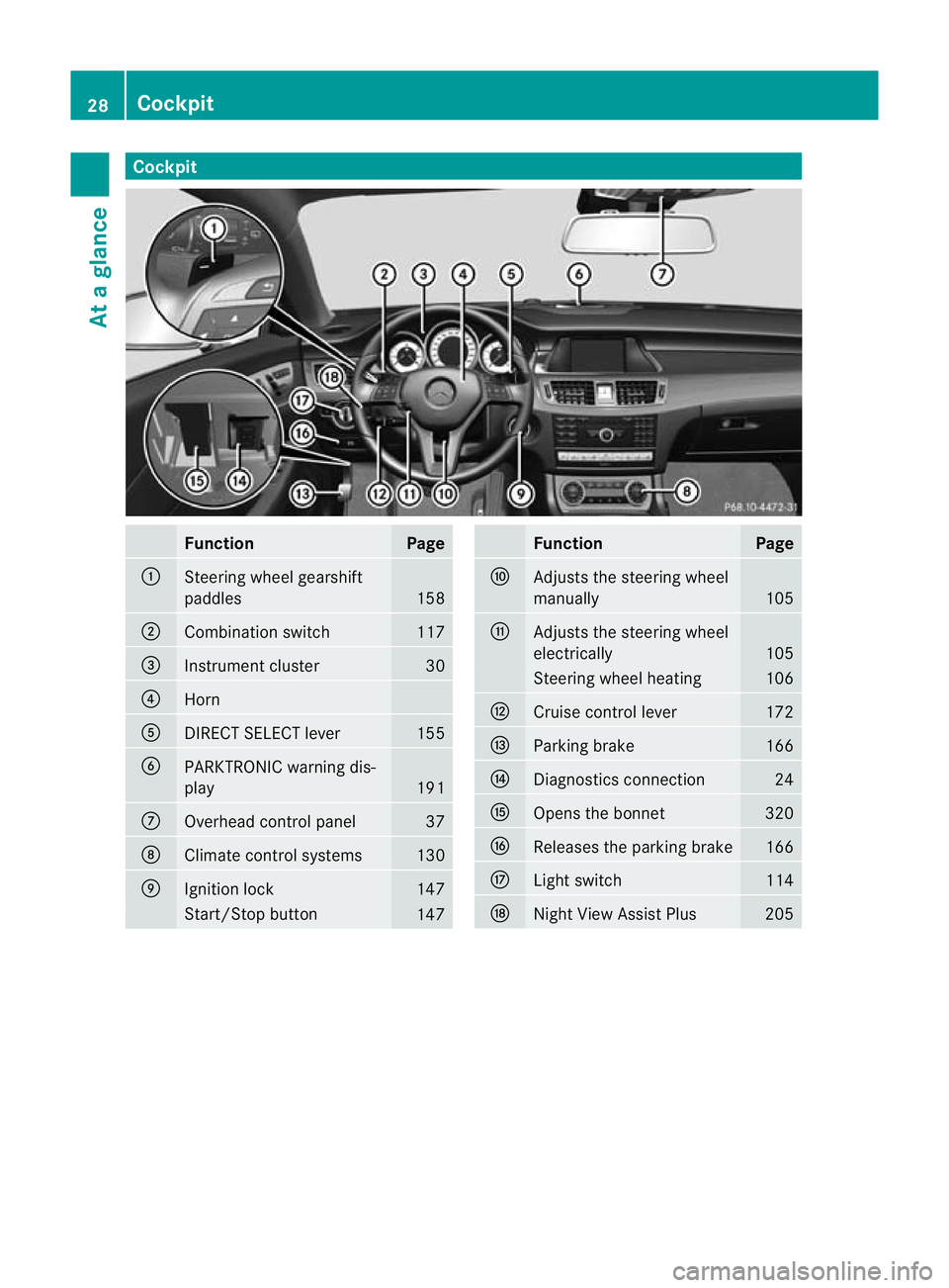
Cockpit
Function Page
:
Steering wheel gearshift
paddles
158
;
Combination switch 117
=
Instrument cluster 30
?
Horn
A
DIRECT SELECT lever 155
B
PARKTRONIC warning dis-
play
191
C
Overhead control panel 37
D
Climate control systems 130
E
Ignition lock 147
Start/Stop button
147 Function Page
F
Adjusts the steering wheel
manually 105
G
Adjusts the steering wheel
electrically 105
Steering wheel heating 106
H
Cruise control lever 172
I
Parking brake 166
J
Diagnostics connection 24
K
Opens the bonnet 320
L
Releases the parking brake 166
M
Ligh
tswitch 114
N
Night View Assist Plus 20528
CockpitAt a glance
Page 32 of 405
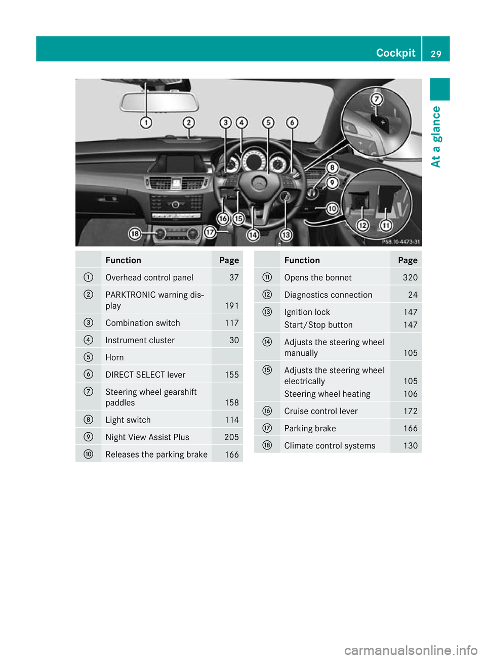
Function Page
:
Overhead control panel 37
;
PARKTRONIC warning dis-
play
191
=
Combination switch 117
?
Instrument cluster 30
A
Horn
B
DIRECT SELECT lever 155
C
Steering wheel gearshift
paddles
158
D
Ligh
tswitch 114
E
Nigh
tView Assist Plus 205
F
Releases the parking brake
166 Function Page
G
Opens the bonnet 320
H
Diagnostics connection 24
I
Ignition lock 147
Start/Stop button 147
J
Adjusts the steering wheel
manually
105
K
Adjusts the steering wheel
electrically
105
Steering wheel heating 106
L
Cruise control lever 172
M
Parking brake 166
N
Climate control systems 130Cockpit
29At a glance
Page 43 of 405
Useful information
i This Owner's Manual describes all mod-
els, series and optional equipment for your
vehicle that were available at the time of
going to press. National variations are pos-
sible. Note that your vehicle may not be
equipped with all of the functions descri-
bed. This is also the case for systems and
functions relevant to safety.
i Read the information on qualified special-
ist workshops: (Y page 24). Panic alarm
X
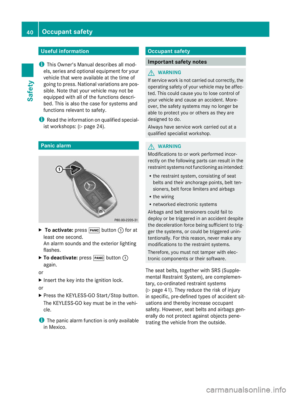
To activate: press!button :for at
least one second.
An alarm sounds and the exterior lighting
flashes.
X To deactivate: press!button :
again.
or
X Insert the key into the ignition lock.
or
X Press the KEYLESS-GO Start/Stop button.
The KEYLESS-GO key must be in the vehi-
cle.
i The panic alarm function is only available
in Mexico. Occupant safety
Important safety notes
G
WARNING
If service work is not carried out correctly, the
operating safety of your vehicle may be affec-
ted. This could cause you to lose control of
your vehicle and cause an accident. More-
over, the safety system smay no longer be
able to protect you or others as they are
designed to do.
Always have service work carried out at a
qualified specialist workshop. G
WARNING
Modifications to or work performed incor-
rectly on the following parts can result in the
restraint systems no tfunctioning as intended:
R the restraint system, consisting of seat
belts and their anchorage points, belt ten-
sioners, belt force limiters and airbags
R the wiring
R networked electronic systems
Airbags and belt tensioners could fail to
deploy or be triggered in an acciden tdespite
the deceleration force being sufficien tto trig-
ger the systems, or could be triggered unin-
tentionally. For this reason, never make any
modifications to the restraint systems.
Therefore, you must not tamper with elec-
tronic components or their software.
The seat belts, together with SRS (Supple-
mental Restraint System), are complemen-
tary, co-ordinated restraint systems
(Y page 41). They reduce the risk of injury
in specific, pre-defined types of accident sit-
uations and thereby increase occupant
safety. However, seat belts and airbags gen-
erally do not protect against objects pene-
trating the vehicle from the outside. 40
Occupant safetySafety
Page 44 of 405
To ensure that the restraint systems can
deliver their full potential protection, make
sure that:
R the seat and head restraint are adjusted
properly (Y page 98).
R the seat belt has been fastened properly
(Y page 49).
R the airbags can inflate unrestricted if
deployed (Y page 42).
R the steering wheel is adjusted properly
(Y page 105).
R the restraint systems have not been modi-
fied.
An airbag increases the protection of vehicle
occupants wearing a seat belt. However, air-
bags are only an additional restraint system
which complements, but does not replace,
the seat belt. All vehicle occupants must wear
their seat belt correctly at all times, even if
the vehicle is equipped with airbags. The air-
bags are not deployed in all types of acci-
dents .For example, if the protective capacity
of correctly fastened seat belts is not
increased by deploying the airbags, the air-
bags will not deploy.
Airbag deployment only provides increased
protection if the seat belt is worn correctly.
First, the seat belt helps to keep the vehicle
occupant in the best position in relation to the
airbag. Second, in a head-on collision, for
example, the seat belt prevents the vehicle
occupant from being propelled towards the
point of impact. SRS (Supplemental Restraint System)
Introduction SRS consists of:
R
the 6 SRS warning lamp
R airbags
R the airbag control unit with crash sensors
R belt tensioners
R belt force limiters SRS reduces the risk of occupants coming
into contact with the vehicle's interior in the
event of an accident. It can also reduce the
forces to which occupant
sare subjected dur-
ing an accident.
SRS warning lamp G
WARNING
If SRS is malfunctioning, individual systems
may be triggered unintentionally or might not
be triggered in the event of an accident with
a high rate of vehicle deceleration.
A malfunction has occurred if:
R the 6 SRS warning lamp does not light
up when the ignitio nis switched on.
R the engine is running and the 6SRS
warning lamp does not go out after a few
seconds.
R the engine is running and the 6SRS
warning lamp lights up again.
In this case, have SRS checked immediately
at a qualified specialist workshop.
SRS functions are checked regularly when
you switch on the ignition and when the
engine is running. Therefore, malfunctions
can be detected in good time.
The 6 SRS warning lamp in the instrument
cluster lights up when the ignition is switched
on. It goes out no later than a few seconds
after the engine is started.
Triggering of belt tensioners, belt force
limiters and airbags During the first stage of a collision, the airbag
control unit evaluates important physical
data relating to vehicle deceleration or accel-
eration, such as:
R
duration
R direction
R magnitude
Based on the evaluation of this data, the air-
bag control unit pre-emptively triggers the
belt tensioners in the first stage. Occupant safety
41Safety Z
Page 53 of 405
been approved by Mercedes-Benz for your
vehicle.
Seat belts are the most effective means of
restraining the movement of vehicle occu-
pants in the event of an accident. This
reduces the risk of vehicle occupants coming
into contact with parts of the vehicle interior.
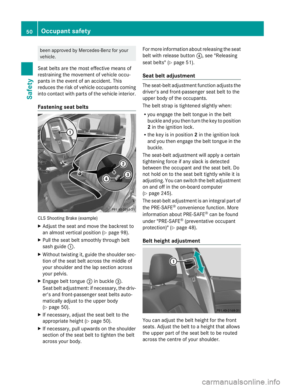
Fastening seat belts CLS Shooting Brake (example)
X Adjust the seat and move the backrest to
an almost vertical position (Y page 98).
X Pull the seat belt smoothly through belt
sash guide :.
X Without twisting it, guide the shoulder sec-
tion of the seat belt across the middle of
your shoulder and the lap section across
your pelvis.
X Engage belt tongue ;in buckle =.
Seat belt adjustment :ifnecessary, the driv-
er's and front-passenger seat belts auto-
matically adjust to the upper body
(Y page 50).
X If necessary, adjust the seat belt to the
appropriate height (Y page 50).
X If necessary, pull upwards on the shoulder
section of the seat belt to tighten the belt
across your body. For more information about releasing the seat
belt with release button
?, see "Releasing
seat belts" (Y page 51).
Seat belt adjustment The seat-belt adjustment function adjusts the
driver's and front-passenger seat belt to the
upper body of the occupants.
The belt strap is tightened slightly when:
R
you engage the belt tongue in the belt
buckle and you then turn the key to position
2in the ignition lock.
R the key is in position 2in the ignition lock
and you then engage the belt tongue in the
buckle.
The seat-belt adjustment will apply a certain
tightening force if any slack is detected
between the occupant and the seat belt. Do
not hold on to the seat belt tightly while it is
adjusting. You can switch the belt adjustment
on and off in the on-board computer
(Y page 245).
The seat-belt adjustment is an integral part of
the PRE-SAFE ®
convenience function. More
information about PRE-SAFE ®
can be found
under "PRE-SAFE ®
(preventative occupant
protection)" (Y page 48).
Belt height adjustment You can adjust the belt height for the front
seats. Adjust the belt to a height that allows
the upper part of the seat belt to be routed
across the centre of your shoulder.50
Occupant safetySafety
Page 55 of 405
Rear seat belt status indicator
Rear sea
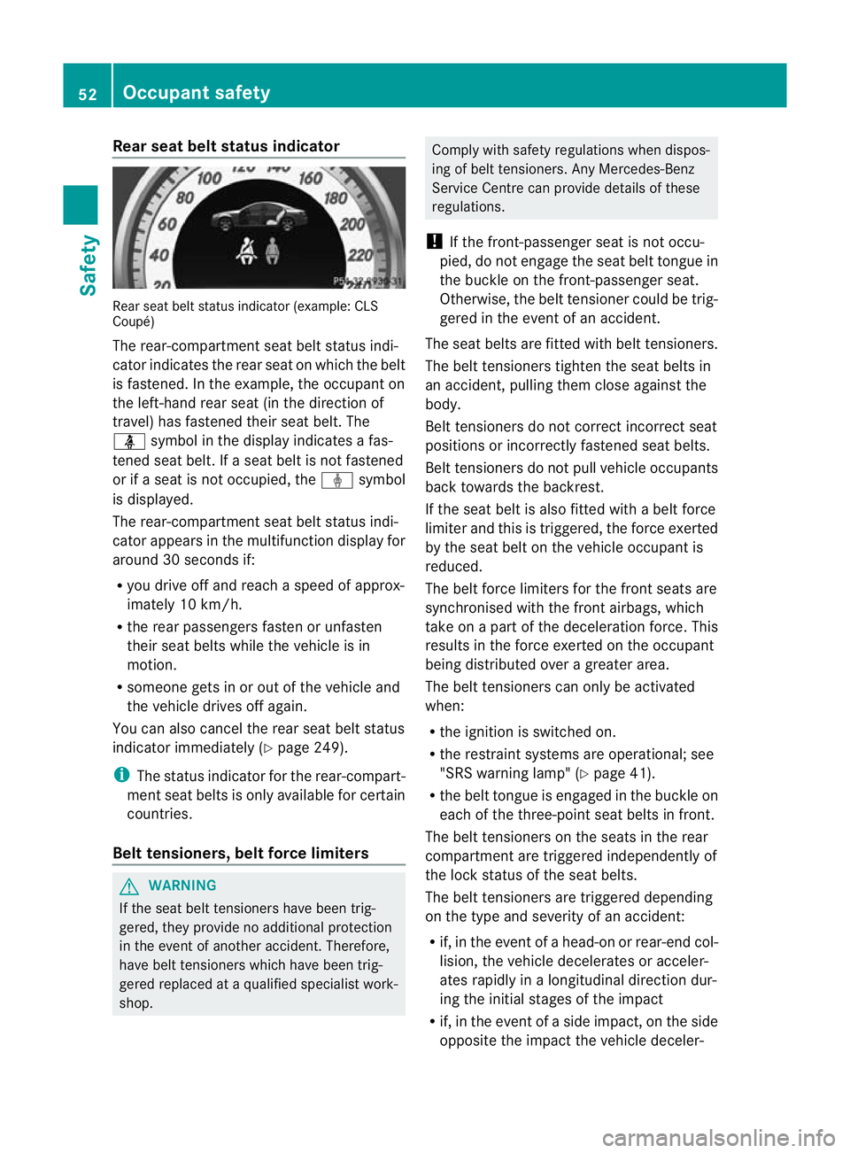
tbelt status indicato r(example: CLS
Coupé)
The rear-compartment seat belt status indi-
cator indicates the rear seat on which the belt
is fastened. In the example, the occupant on
the left-hand rear seat (in the direction of
travel) has fastened their seat belt. The
ü symbol in the display indicates a fas-
tened seat belt. If a seat belt is not fastened
or if a seat is not occupied, the ýsymbol
is displayed.
The rear-compartment seat belt status indi-
cator appears in the multifunction display for
around 30 seconds if:
R you drive off and reach a speed of approx-
imately 10 km/h.
R the rear passengers fasten or unfasten
their seat belts while the vehicle is in
motion.
R someone gets in or out of the vehicle and
the vehicle drives off again.
You can also cancel the rear seat belt status
indicato rimmediately (Y page 249).
i The status indicator for the rear-compart-
ment seat belts is only available for certain
countries.
Belt tensioners, beltf orce limitersG
WARNING
If the seat belt tensioners have been trig-
gered, they provide no additional protection
in the event of another accident. Therefore,
have belt tensioners which have been trig-
gered replaced at a qualified specialist work-
shop. Comply with safety regulations when dispos-
ing of belt tensioners. Any Mercedes-Benz
Service Centre can provide details of these
regulations.
! If the front-passenger seat is not occu-
pied, do no tengage the sea tbelt tongue in
the buckle on the front-passenger seat.
Otherwise, the belt tensioner could be trig-
gered in the event of an accident.
The seat belts are fitted with belt tensioners.
The belt tensioners tighten the seat belts in
an accident, pulling them close against the
body.
Belt tensioners do not correct incorrect seat
positions or incorrectly fastened seat belts.
Belt tensioners do not pull vehicle occupants
back towards the backrest.
If the seat belt is also fitted with a belt force
limiter and this is triggered, the force exerted
by the seat belt on the vehicle occupan tis
reduced.
The belt force limiters for the front seats are
synchronised with the front airbags, which
take on a part of the deceleration force. This
results in the force exerted on the occupant
being distributed over a greater area.
The beltt ensioners can only be activated
when:
R the ignition is switched on.
R the restraint systems are operational; see
"SRS warning lamp" (Y page 41).
R the belt tongue is engaged in the buckle on
each of the three-point seat belts in front.
The belt tensioners on the seats in the rear
compartment are triggered independently of
the lock status of the seat belts.
The belt tensioners are triggered depending
on the type and severity of an accident:
R if, in the event of a head-on or rear-end col-
lision, the vehicle decelerates or acceler-
ates rapidly in a longitudinal direction dur-
ing the initial stages of the impact
R if, in the event of a side impact, on the side
opposite the impact the vehicle deceler- 52
Occupant safetySafety
Page 58 of 405
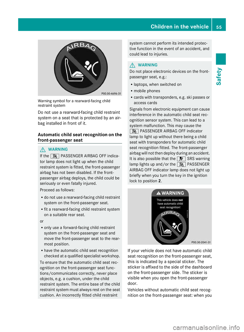
Warning symbol for a rearward-facing child
restraint system
Do not use a rearward-facing child restraint
system on a seat that is protected by an air-
bag installed in fron tofit.
Automatic chil dseat recognition on the
front-passenger seat G
WARNING
If the 4 PASSENGER AIRBAG OFF indica-
to rlamp does no tlight up when the child
restraint system is fitted, the front-passenger
airbag has not been disabled. If the front-
passenger airbag deploys, the child could be
seriously or even fatally injured.
Proceed as follows:
R do not use a rearward-facing child restraint
system on the front-passenge rseat.
R fit a rearward-facing child restraint system
on a suitable rear seat.
or
R only use a forward-facing child restraint
system on the front-passenger seat and
move the front-passenger seat to the rear-
most position.
R have the automatic child seat recognition
checked at a qualified specialist workshop.
To ensure that the automatic child seat rec-
ognition on the front-passenger seat func-
tions/communicates correctly, never place
objects, e.g. a cushion, under the child
restraint system. The entire base of the child
restraint system must always rest on the seat
cushion. An incorrectly fitted child restraint system cannot perform its intended protec-
tive function in the event of an accident, and
could lead to injuries.
G
WARNING
Do not place electronic devices on the front-
passenger seat, e.g.:
R laptops, when switched on
R mobile phones
R cards with transponders, e.g. ski passes or
access cards
Signals from electronic equipment can cause
interference in the automatic child seat rec-
ognition sensor system. This can lead to a
system malfunction. This may cause the
4 PASSENGER AIRBAG OFF indicator
lamp to light up without there being a child
seat with transponders for automatic child
seat recognition fitted. The front-passenger
airbag will not then deploy during an accident.
It is also possible that the 6SRS warning
lamp lights up and/or the 4PASSENGER
AIRBAG OFF indicator lamp does not light up
briefly when you turn the key in the ignition
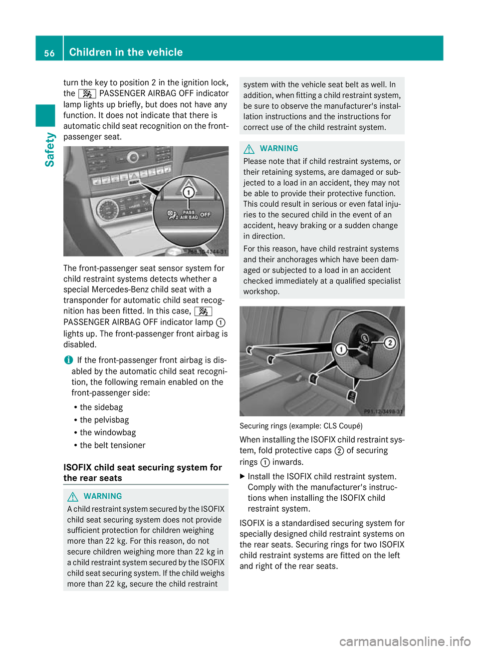
lock to position 2. If your vehicle does not have automatic child
seat recognition on the front-passenger seat,
this is indicated by a special sticker. The
sticker is affixed to the side of the dashboard
on the front-passenger side. The sticker is
visible when you open the front-passenger
door.
Vehicles without automatic child seat recog-
nition on the front-passenger seat: when you Children in the vehicle
55Safety Z
Page 59 of 405
tur
nthe key to position 2inthe ignition lock,
the 4 PASSENGER AIRBAG OFF indicator
lamp lights up briefly, but does not have any
function. It does not indicate that there is
automatic child seat recognition on the front-
passenger seat. The front-passenger seat sensor system for
child restraint systems detects whether a
special Mercedes-Ben zchild seat with a
transponder for automatic child seat recog-
nition has been fitted. In this case, 4
PASSENGER AIRBAG OFF indicator lamp :
lights up. The front-passenger front airbag is
disabled.
i If the front-passenger front airbag is dis-
abled by the automatic child seat recogni-
tion, the following remain enabled on the
front-passenger side:
R the sidebag
R the pelvisbag
R the windowbag
R the belt tensioner
ISOFIX child seat securing system for
the rear seats G
WARNING
Ac hild restraint system secured by the ISOFIX
child seat securing system does not provide
sufficient protection for children weighing
more than 22 kg. For this reason, do not
secure children weighing more than 22 kg in
a child restraint system secured by the ISOFIX
child seat securing system. If the child weighs
more than 22 kg, secure the child restraint system with the vehicle seat belt as well. In
addition, when fitting a child restraint system,
be sure to observe the manufacturer's instal-
lation instructions and the instructions for
correct use of the child restraint system.
G
WARNING
Please note that if child restraint systems, or
their retaining systems, are damaged or sub-
jected to a load in an accident, they may not
be able to provide their protective function.
This could result in serious or even fatal inju-
ries to the secured child in the event of an
accident, heavy braking or a sudden change
in direction.
For this reason, have child restraint systems
and their anchorages which have been dam-
aged or subjected to a load in an accident
checked immediately at a qualified specialist
workshop. Securing rings (example: CLS Coupé)
When installing the ISOFIX child restraint sys-
tem, fold protective caps
;of securing
rings :inwards.
X Install the ISOFIX child restraint system.
Comply with the manufacturer's instruc-
tions when installing the ISOFIX child
restraint system.
ISOFIX is a standardised securing system for
specially designed child restraint systems on
the rear seats. Securing rings for two ISOFIX
child restraint systems are fitted on the left
and right of the rear seats. 56
Children in the vehicleSafety