MERCEDES-BENZ CLS550 2010 W219 Owner's Manual
Manufacturer: MERCEDES-BENZ, Model Year: 2010, Model line: CLS550, Model: MERCEDES-BENZ CLS550 2010 W219Pages: 308, PDF Size: 5.82 MB
Page 261 of 308
Tires
Problem
Possible causes/consequences and
X Solutionsh
USA only:
Combination
low
tire pressure
telltale/TPMS
malfunction
telltale for the
TPMS
illuminates
continuously.
Canada only:
Low tire
pressure telltale
for the
Advanced TPMS
illuminates
continuously. The TPMS (USA only) or Advanced TPMS (Canada only) detects a
loss of pressure in at least one tire.
X
Carefully bring the vehicle to a halt, avoiding abrupt steering and
braking maneuvers. Observe the traffic situation around you.
X Read and observe messages in the multifunction display
(Y page 228).
If the tire inflation pressure in the respective tire(s) has (have) been
corrected, the combination low tire pressure/TPMS malfunction
telltale goes out after a few minutes of driving. h
USA only:
Combination
low
tire pressure
telltale/TPMS
malfunction
telltale for the
TPMS flashes 60
seconds and
then stays
illuminated. There is a malfunction in the TPMS.
X
Read and observe messages in the multifunction display
(Y page 228).
X Have the TPMS checked at an authorized Mercedes-Benz
Center.
After the malfunction has been remedied, the combination low tire
pressure/TPMS
malfunction telltale goes out after a few minutes
of driving. G
Warning!
Each tire, including the spare (if provided),
should be checked at least once a month
when cold and inflated to the inflation
pressure recommended by the vehicle
manufacturer on the Tire and Loading
Information placard on the driver’s door B-
pillar
or the tire inflation pressure label on the
inside of the fuel filler flap. If your vehicle has
tires of a different size than the size indicated
on the Tire and Loading Information placard
or the tire inflation pressure label, you should
determine the proper tire inflation pressure
for those tires. As an added safety feature, your vehicle has
been
equipped with a tire pressure monitoring
system (TPMS) that illuminates a low tire
pressure telltale when one or more of your
tires are significantly underinflated.
Accordingly, when the low tire pressure
telltale illuminates, you should stop and check
your tires as soon as possible, and inflate
them to the proper pressure. Driving on a
significantly underinflated tire causes the tire
to overheat and can lead to tire failure.
Underinflation also reduces fuel efficiency
and tire tread life, and may affect the vehicle’s
handling and stopping ability. Please note that What to do if …
259
Practical hints
219_AKB; 4; 54, en-US
d2ureepe, Version: 2.11.8.1 2009-05-11T16:21:02+02:00 - Seite 259 Z
Page 262 of 308
the TPMS is not a substitute for proper tire
maintenance, and it is the driver’s
responsibility to maintain correct tire
pressure, even if underinflation has not
reached
the level to trigger illumination of the
TPMS low tire pressure telltale.
USA only:
Your vehicle has also been equipped with a
TPMS malfunction indicator to indicate when
the system is not operating properly. The
TPMS malfunction indicator is combined with
the low tire pressure telltale. When the
system detects a malfunction, the telltale will
flash for approximately 1 minute and then
remain continuously illuminated. This sequence will continue upon subsequent
vehicle start-ups as long as the malfunction
exists. When the malfunction indicator is
illuminated, the system may not be able to
detect
or signal low tire pressure as intended.
TPMS malfunctions may occur for a variety of
reasons, including the installation of
incompatible replacement or alternate tires
or wheels on the vehicle that prevent the
TPMS from functioning properly. Always
check the TPMS malfunction telltale after
replacing one or more tires or wheels on your
vehicle to ensure that the replacement or
alternate tires and wheels allow the TPMS to
continue to function properly. Lamp in center console
Problem
Possible causes/consequences and
X Solutions04
The front passenger
front air bag off
indicator lamp
illuminates and
remains illuminated
with the weight of a
typical adult or
someone larger than a
small individual on the
front passenger seat.
The system is malfunctioning.
X
Have the system checked as soon as possible at an authorized
Mercedes-Benz Center.
X Read and observe messages in the multifunction display and
follow corrective steps (Y page 228). G
Warning!
If the 04 indicator lamp
illuminates and remains illuminated with the
weight of a typical adult or someone larger than a small individual on the front passenger
seat,
do not have any passenger use the front
passenger seat until the system has been
repaired. 260
What to do if …
Practical hints
219_AKB; 4; 54, en-US
d2ureepe,
Version: 2.11.8.1 2009-05-11T16:21:02+02:00 - Seite 260
Page 263 of 308
Problem
Possible causes/consequences and
X Solutions04
The front passenger
front air bag off
indicator lamp does not
illuminate and/or does
not remain illuminated
with the weight of a
typical 12-month-old
child in a standard child
restraint or less on the
front passenger seat.
The system is malfunctioning.
X
Make sure there is nothing between seat cushion and child seat
and check installation of the child seat.
X Make sure no objects applying supplemental weight onto the
seat are present.
X Make sure no objects which apply forces to the seat are present
(e.g. objects such as books, briefcases etc. lodged behind or
around the seat, head restraints pushing against roof etc.). The
system may recognize such forces as supplemental weight.
X If the front passenger front air bag off indicator lamp remains
out, have the system checked as soon as possible at an
authorized Mercedes-Benz Center. Do not transport a child on
the front passenger seat until the system has been repaired.
X Read and observe messages in the multifunction display and
follow corrective steps (Y page 228). G
Warning!
If the 04 indicator lamp does not
illuminate or remains out with the weight of a
typical 12-month-old child in a standard child
restraint or less on the front passenger seat,
do not transport a child on the front
passenger seat until the system has been
repaired. Unlocking/locking manually
Unlocking the vehicle
If you cannot unlock the vehicle with the
SmartKey or with KEYLESS-GO, unlock the
driver’s door and the trunk using the
mechanical key.
The anti-theft alarm system will trigger when
you
R unlock the driver’s door or the trunk with
the mechanical key
and
R open the driver’s door or the trunk
To cancel the alarm, insert the SmartKey into
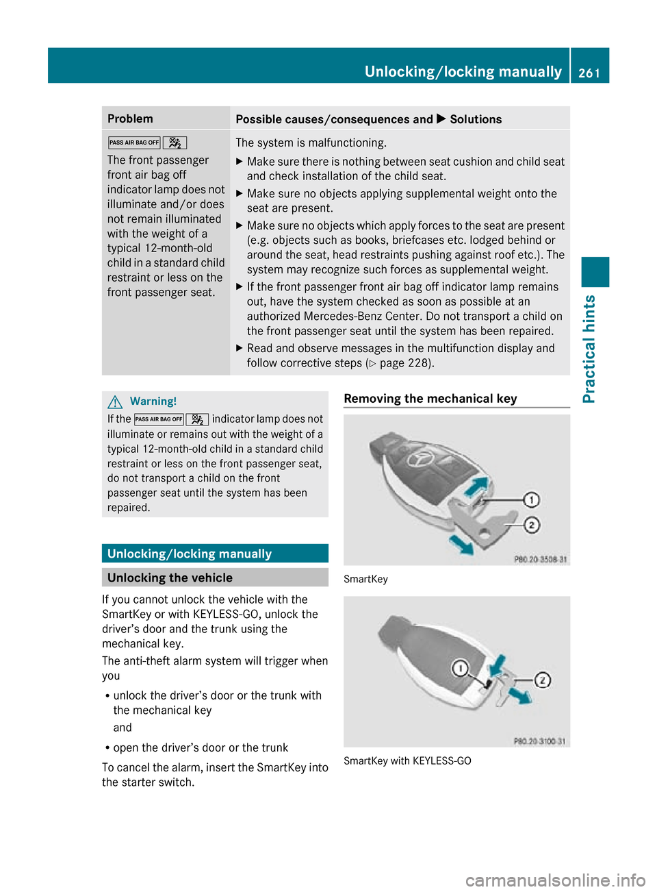
the starter switch. Removing the mechanical key
SmartKey
SmartKey with KEYLESS-GO Unlocking/locking manually
261Practical hints
219_AKB; 4; 54, en-US
d2ureepe, Version: 2.11.8.1 2009-05-11T16:21:02+02:00 - Seite 261 Z
Page 264 of 308
X
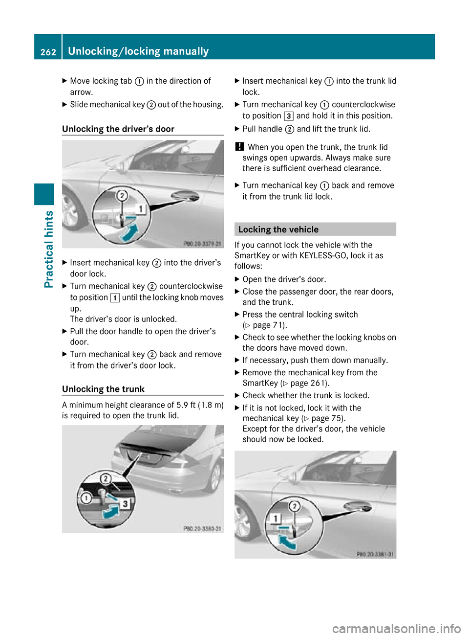
Move locking tab : in the direction of
arrow.
X Slide mechanical key ; out of the housing.
Unlocking the driver’s door X
Insert mechanical key ; into the driver’s
door lock.
X Turn mechanical key ; counterclockwise
to position 1 until the locking knob moves
up.
The driver’s door is unlocked.
X Pull the door handle to open the driver’s
door.
X Turn mechanical key ; back and remove
it from the driver’s door lock.
Unlocking the trunk A minimum height clearance of 5.9 ft (1.8 m)
is required to open the trunk lid. X
Insert mechanical key : into the trunk lid
lock.
X Turn mechanical key : counterclockwise
to position 3 and hold it in this position.
X Pull handle ; and lift the trunk lid.
! When you open the trunk, the trunk lid
swings open upwards. Always make sure
there is sufficient overhead clearance.
X Turn mechanical key : back and remove
it from the trunk lid lock. Locking the vehicle
If you cannot lock the vehicle with the
SmartKey or with KEYLESS-GO, lock it as
follows:
X Open the driver’s door.
X Close the passenger door, the rear doors,
and the trunk.
X Press the central locking switch
(Y page 71).
X Check to see whether the locking knobs on
the doors have moved down.
X If necessary, push them down manually.
X Remove the mechanical key from the
SmartKey (Y page 261).
X Check whether the trunk is locked.
X If it is not locked, lock it with the
mechanical key ( Y page 75).
Except for the driver’s door, the vehicle
should now be locked. 262
Unlocking/locking manuallyPractical hints
219_AKB; 4; 54, en-US
d2ureepe,
Version: 2.11.8.1 2009-05-11T16:21:02+02:00 - Seite 262
Page 265 of 308
X
Insert mechanical key ; into the driver’s
door lock.
X Turn mechanical key ; clockwise to
position 1.
The driver’s door is locked.
X Turn mechanical key ; back and remove
it from the driver’s door lock.
i This procedure does not arm the anti-
theft alarm system, nor does it lock the fuel
filler flap. Manually unlocking the gear selector
lever
If the vehicle’s electrical system is
malfunctioning, the gear selector lever could
remain locked in park position P. In this case
the gear selector lever can be unlocked
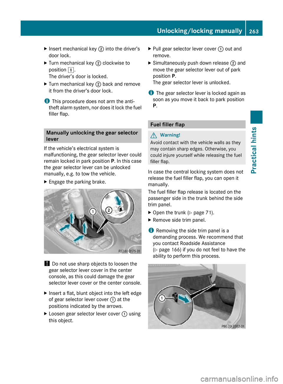
manually, e.g. to tow the vehicle.
X Engage the parking brake. !
Do not use sharp objects to loosen the
gear selector lever cover in the center
console, as this could damage the gear
selector lever cover or the center console.
X Insert a flat, blunt object into the left edge
of gear selector lever cover : at the
positions indicated by the arrows.
X Loosen gear selector lever cover : using
this object. X
Pull gear selector lever cover : out and
remove.
X Simultaneously push down release ; and
move the gear selector lever out of park
position P.
The gear selector lever is unlocked.
i The gear selector lever is locked again as
soon as you move it back to park position
P. Fuel filler flap
G
Warning!
Avoid contact with the vehicle walls as they
may contain sharp edges. Otherwise, you
could injure yourself while releasing the fuel
filler flap.
In case the central locking system does not
release the fuel filler flap, you can open it
manually.
The fuel filler flap release is located on the
passenger side in the trunk behind the side
trim panel.
X Open the trunk (Y page 71).
X Remove side trim panel.
i Removing the side trim panel is a
demanding process. We recommend that
you contact Roadside Assistance
(Y page 166) if you do not feel to have the
ability to perform this process. Unlocking/locking manually
263Practical hints
219_AKB; 4; 54, en-US
d2ureepe, Version: 2.11.8.1 2009-05-11T16:21:02+02:00 - Seite 263 Z
Page 266 of 308
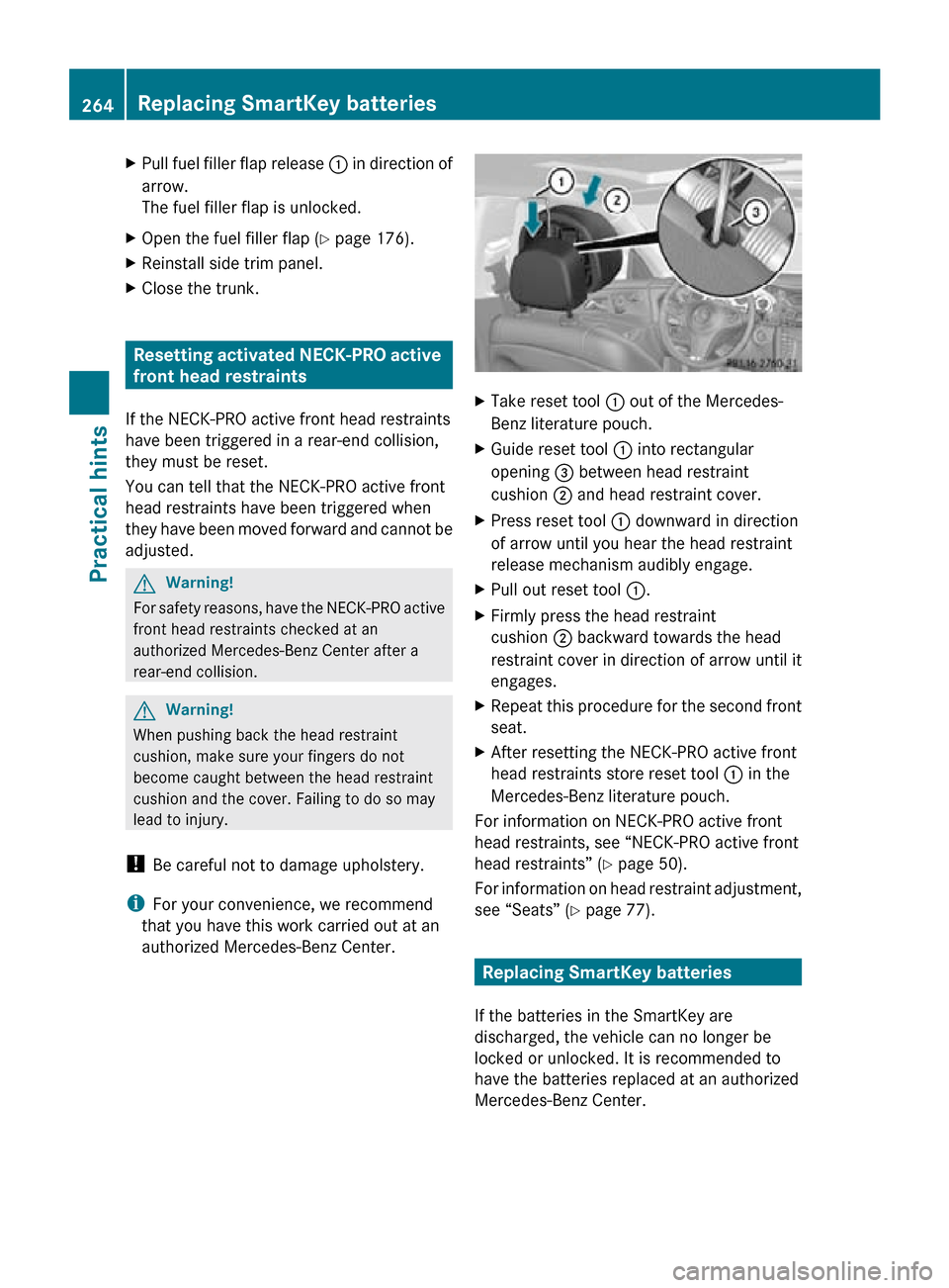
X
Pull fuel filler flap release : in direction of
arrow.
The fuel filler flap is unlocked.
X Open the fuel filler flap ( Y page 176).
X Reinstall side trim panel.
X Close the trunk. Resetting activated NECK-PRO active
front head restraints
If the NECK-PRO active front head restraints
have been triggered in a rear-end collision,
they must be reset.
You can tell that the NECK-PRO active front
head restraints have been triggered when
they have been moved forward and cannot be
adjusted. G
Warning!
For safety reasons, have the NECK-PRO active
front head restraints checked at an
authorized Mercedes-Benz Center after a
rear-end collision. G
Warning!
When pushing back the head restraint
cushion, make sure your fingers do not
become caught between the head restraint
cushion and the cover. Failing to do so may
lead to injury.
! Be careful not to damage upholstery.
i For your convenience, we recommend
that you have this work carried out at an
authorized Mercedes-Benz Center. X
Take reset tool : out of the Mercedes-
Benz literature pouch.
X Guide reset tool : into rectangular
opening = between head restraint
cushion ; and head restraint cover.
X Press reset tool : downward in direction
of arrow until you hear the head restraint
release mechanism audibly engage.
X Pull out reset tool :.
X Firmly press the head restraint
cushion ; backward towards the head
restraint cover in direction of arrow until it
engages.
X Repeat this procedure for the second front
seat.
X After resetting the NECK-PRO active front
head restraints store reset tool : in the
Mercedes-Benz literature pouch.
For information on NECK-PRO active front
head restraints, see “NECK-PRO active front
head restraints” ( Y page 50).
For information on head restraint adjustment,
see “Seats” ( Y page 77). Replacing SmartKey batteries
If the batteries in the SmartKey are
discharged, the vehicle can no longer be
locked or unlocked. It is recommended to
have the batteries replaced at an authorized
Mercedes-Benz Center. 264
Replacing SmartKey batteriesPractical hints
219_AKB; 4; 54, en-US
d2ureepe,
Version: 2.11.8.1 2009-05-11T16:21:02+02:00 - Seite 264
Page 267 of 308
G
Warning!
Batteries contain poisonous and corrosive
substances. Therefore, keep the batteries out
of reach of children.
If a battery is swallowed, seek medical help
immediately. G
Warning!
SmartKey batteries contain perchlorate
material, which may require special handling
and regard for the environment. Check with
your local government’s disposal guidelines.
California residents, see www.dtsc.ca.gov/
HazardousWaste/Perchlorate/
index.cfm.
Batteries contain materials that can harm the
environment if disposed of improperly.
Recycling of batteries is the preferred method
of disposal. Many states (USA only) or
provinces (Canada only) require sellers of
batteries to accept old batteries for recycling.
When inserting the batteries, make sure they
are clean and free of lint.
When replacing batteries, always replace
both batteries.
i The required replacement batteries are
available at any authorized Mercedes-Benz
Center.
Replacement batteries: Lithium, type
CR 2025 or equivalent.
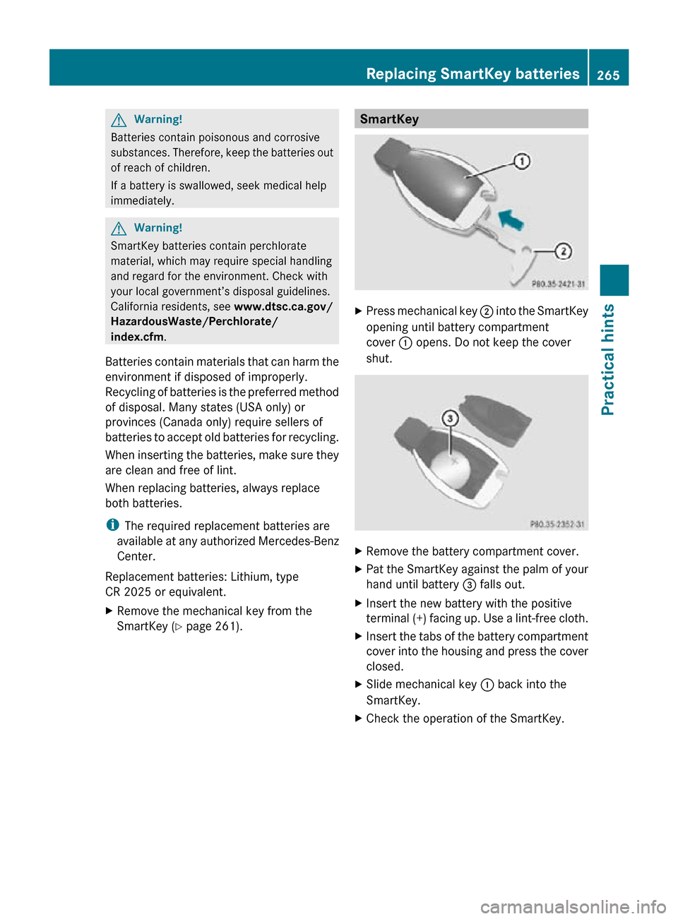
X Remove the mechanical key from the
SmartKey (Y page 261). SmartKey
X
Press mechanical key ; into the SmartKey
opening until battery compartment
cover : opens. Do not keep the cover
shut. X
Remove the battery compartment cover.
X Pat the SmartKey against the palm of your
hand until battery = falls out.
X Insert the new battery with the positive
terminal (+) facing up. Use a lint-free cloth.
X Insert the tabs of the battery compartment
cover into the housing and press the cover
closed.
X Slide mechanical key : back into the
SmartKey.
X Check the operation of the SmartKey. Replacing SmartKey batteries
265Practical hints
219_AKB; 4; 54, en-US
d2ureepe, Version: 2.11.8.1 2009-05-11T16:21:02+02:00 - Seite 265 Z
Page 268 of 308
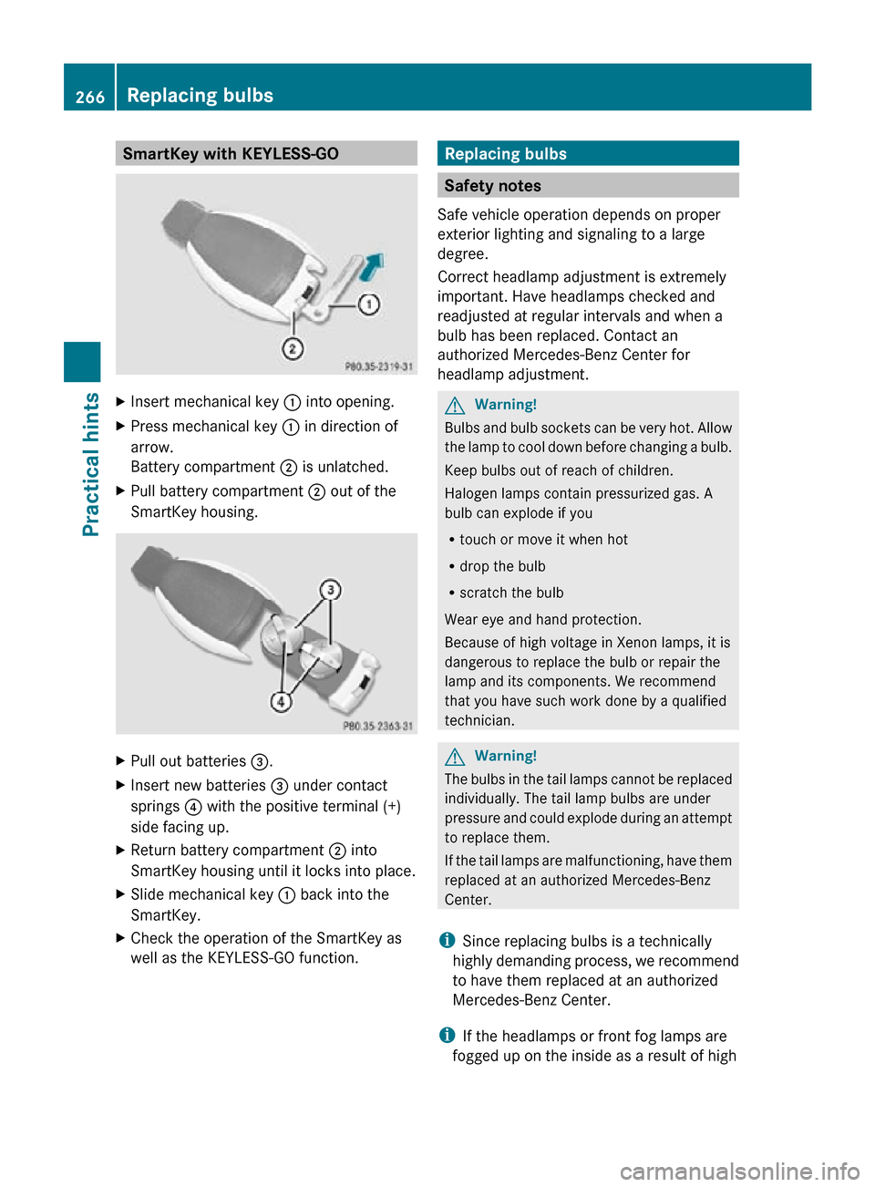
SmartKey with KEYLESS-GO
X
Insert mechanical key : into opening.
X Press mechanical key : in direction of
arrow.
Battery compartment ; is unlatched.
X Pull battery compartment ; out of the
SmartKey housing. X
Pull out batteries =.
X Insert new batteries = under contact
springs ? with the positive terminal (+)
side facing up.
X Return battery compartment ; into
SmartKey housing until it locks into place.
X Slide mechanical key : back into the
SmartKey.
X Check the operation of the SmartKey as
well as the KEYLESS-GO function. Replacing bulbs
Safety notes
Safe vehicle operation depends on proper
exterior lighting and signaling to a large
degree.
Correct headlamp adjustment is extremely
important. Have headlamps checked and
readjusted at regular intervals and when a
bulb has been replaced. Contact an
authorized Mercedes-Benz Center for
headlamp adjustment. G
Warning!
Bulbs and bulb sockets can be very hot. Allow
the lamp to cool down before changing a bulb.
Keep bulbs out of reach of children.
Halogen lamps contain pressurized gas. A
bulb can explode if you
R touch or move it when hot
R drop the bulb
R scratch the bulb
Wear eye and hand protection.
Because of high voltage in Xenon lamps, it is
dangerous to replace the bulb or repair the
lamp and its components. We recommend
that you have such work done by a qualified
technician. G
Warning!
The bulbs in the tail lamps cannot be replaced
individually. The tail lamp bulbs are under
pressure and could explode during an attempt
to replace them.
If the tail lamps are malfunctioning, have them
replaced at an authorized Mercedes-Benz
Center.
i Since replacing bulbs is a technically
highly demanding process, we recommend
to have them replaced at an authorized
Mercedes-Benz Center.
i If the headlamps or front fog lamps are
fogged up on the inside as a result of high 266
Replacing bulbsPractical hints
219_AKB; 4; 54, en-US
d2ureepe,
Version: 2.11.8.1 2009-05-11T16:21:02+02:00 - Seite 266
Page 269 of 308
humidity, driving the vehicle a distance with
the lights on should clear up the fogging.
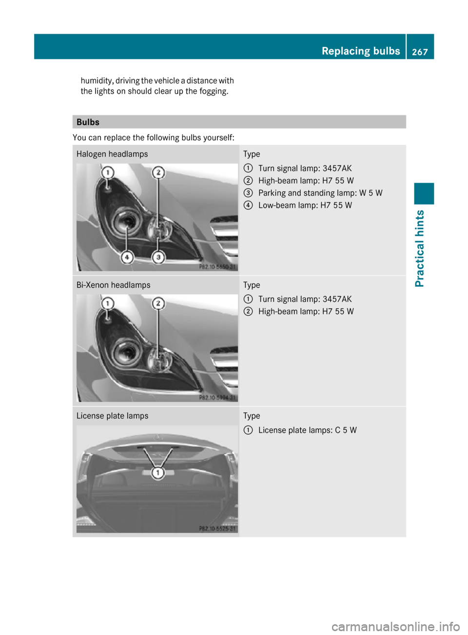
Bulbs
You can replace the following bulbs yourself: Halogen headlamps Type
:
Turn signal lamp: 3457AK
; High-beam lamp: H7 55 W
= Parking and standing lamp: W 5 W
? Low-beam lamp: H7 55 W Bi-Xenon headlamps Type
:
Turn signal lamp: 3457AK
; High-beam lamp: H7 55 W License plate lamps Type
:
License plate lamps: C 5 W Replacing bulbs
267Practical hints
219_AKB; 4; 54, en-US
d2ureepe, Version: 2.11.8.1 2009-05-11T16:21:02+02:00 - Seite 267 Z
Page 270 of 308
Notes on bulb replacement
!
Do not replace LEDs or bulbs not
described in this section. You could
otherwise damage the LEDs, the bulbs or
parts of the vehicle. Only have the LEDs and
bulbs replaced at an authorized Mercedes-
Benz Center. G
Observe Safety notes, see page 266.
R Only use 12-volt bulbs of the same type and
with the specified watt rating.
R Switch the lights off before changing a bulb
to prevent short circuits.
R Always use a clean lint-free cloth when
handling bulbs.
R Your hands should be dry and free of oil and
grease.
R If the newly installed bulb does not come
on, contact an authorized Mercedes-Benz
Center.
i Mercedes-Benz recommends using
Longlife (LL) bulbs. Replacing bulbs for front lamps
G
Warning!
Do not remove the cover for the Bi-Xenon
headlamp. Because of high voltage in Xenon
lamps, it is dangerous to replace the bulb or
repair the lamp and its components. It is
recommended to have such work done by a
qualified technician.
Before you start to replace a bulb for a front
lamp, do the following:
X Switch off the ignition.
X Turn the exterior lamp switch to position
$.
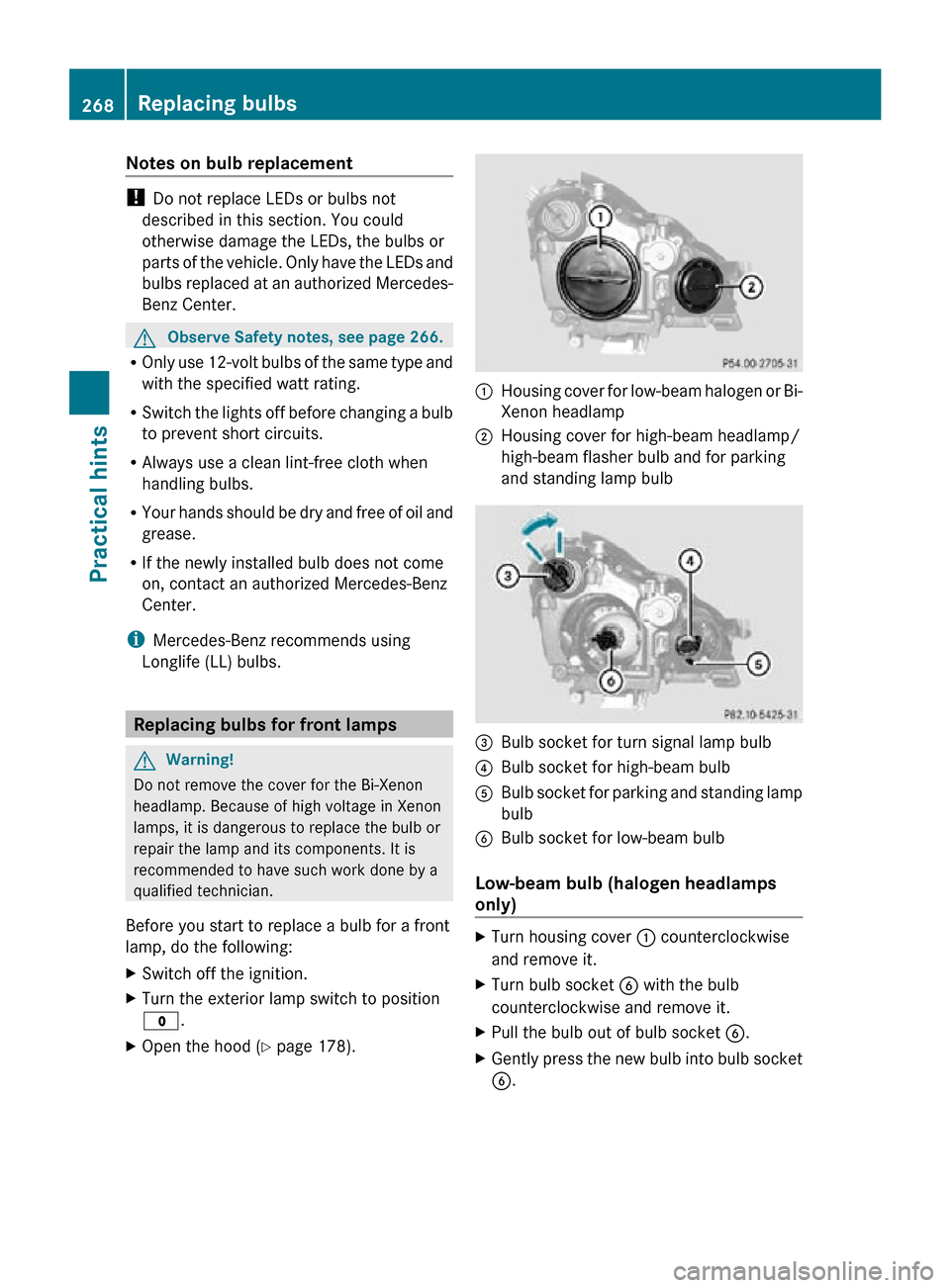
X Open the hood (Y page 178). :
Housing cover for low-beam halogen or Bi-
Xenon headlamp
; Housing cover for high-beam headlamp/
high-beam flasher bulb and for parking
and standing lamp bulb =
Bulb socket for turn signal lamp bulb
? Bulb socket for high-beam bulb
A Bulb socket for parking and standing lamp
bulb
B Bulb socket for low-beam bulb
Low-beam bulb (halogen headlamps
only) X
Turn housing cover : counterclockwise
and remove it.
X Turn bulb socket B with the bulb
counterclockwise and remove it.
X Pull the bulb out of bulb socket B.
X Gently press the new bulb into bulb socket
B. 268
Replacing bulbsPractical hints
219_AKB; 4; 54, en-US
d2ureepe,
Version: 2.11.8.1 2009-05-11T16:21:02+02:00 - Seite 268