MERCEDES-BENZ CLS550 2010 W219 Owner's Manual
Manufacturer: MERCEDES-BENZ, Model Year: 2010, Model line: CLS550, Model: MERCEDES-BENZ CLS550 2010 W219Pages: 308, PDF Size: 5.82 MB
Page 271 of 308
X
Place bulb socket B back into the housing
and turn it clockwise until it engages.
X Align housing cover : and turn it
clockwise until it engages.
High-beam and high-beam flasher bulb
(halogen headlamps only)/high-beam
flasher bulb (Bi-Xenon headlamps only) X
Turn housing cover ; counterclockwise
and remove it.
X Turn bulb socket ? with the bulb
counterclockwise and remove it.
X Pull the bulb out of bulb socket ?.
X Gently press the new bulb into bulb
socket ?.
X Place bulb socket ? back into the housing
and turn it clockwise until it engages.
X Align housing cover ; and turn it
clockwise until it engages.
Front turn signal lamp bulb X
Turn bulb socket = with the bulb
counterclockwise and remove it.
X Gently press onto the bulb and turn it
counterclockwise out of bulb socket =.
X Gently press the new bulb into bulb socket
= and turn it clockwise until it engages.
X Place bulb socket = back into the housing
and turn it clockwise until it engages.
Parking and standing lamp bulb Halogen headlamps
X
Turn housing cover ; counterclockwise
and remove it.
X Pull out bulb socket A with the bulb.
X Pull the bulb out of bulb socket A.
X Gently press the new bulb into bulb socket
A.
X Press bulb socket A back into the lamp.
X Align housing cover ; and turn it
clockwise. Bi-Xenon headlamps
In vehicles with Bi-Xenon headlamps, the
bulbs of the parking and standing lamps are
LEDs.
!
Do not replace the LEDs yourself. You
could otherwise damage the LEDs or parts
of the vehicle. Only have the LEDs replaced
at an authorized Mercedes-Benz Center. Replacing bulbs for rear lamps
Tail lamp unit The tail lamps are equipped with HiP bulbs
and LEDs. Have them replaced at an
authorized Mercedes-Benz Center.
G
Observe Safety notes, see page 266.
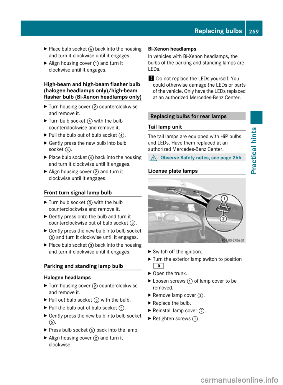
License plate lamps X
Switch off the ignition.
X Turn the exterior lamp switch to position
$.
X Open the trunk.
X Loosen screws : of lamp cover to be
removed.
X Remove lamp cover ;.
X Replace the bulb.
X Reinstall lamp cover ;.
X Retighten screws :. Replacing bulbs
269Practical hints
219_AKB; 4; 54, en-US
d2ureepe, Version: 2.11.8.1 2009-05-11T16:21:02+02:00 - Seite 269 Z
Page 272 of 308
Replacing wiper blades
Safety notes
G
Warning!
For safety reasons, switch off the wipers and
remove the SmartKey from the starter switch
(vehicles with KEYLESS-GO: Make sure the
vehicle’s on-board electronics have status 0)
before replacing a wiper blade. Otherwise, the
wiper motor could suddenly turn on and cause
injury. G
Warning!
Wiper blades are components that are subject
to wear and tear. Replace the wiper blades
twice a year, preferably in the spring and fall.
Otherwise the windshield will not be wiped
properly. As a result, you may not be able to
observe surrounding traffic conditions and
could cause an accident.
! To avoid damage to the hood, the wiper
arms should only be folded forward when
in the vertical position.
! Never open the hood when a wiper arm is
folded forward.
Hold on to the wiper when folding a wiper
arm back. If released, the force of the
impact from the tensioning spring could
crack the windshield.
Do not allow a wiper arm to contact the
windshield glass without a wiper blade
inserted.
Mercedes-Benz recommends that you have
this work carried out at an authorized
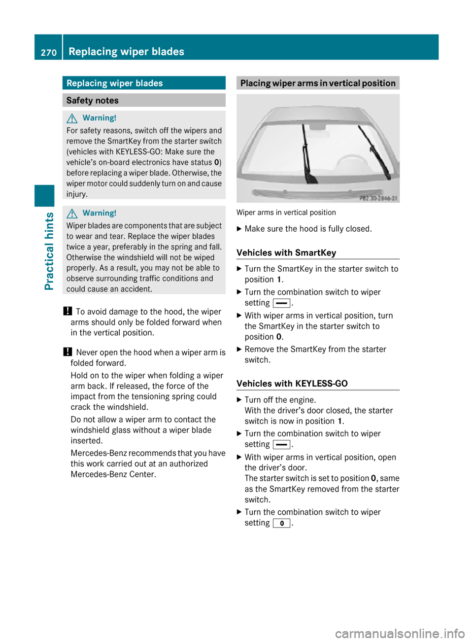
Mercedes-Benz Center. Placing wiper arms in vertical position
Wiper arms in vertical position
X
Make sure the hood is fully closed.
Vehicles with SmartKey X
Turn the SmartKey in the starter switch to
position 1.
X Turn the combination switch to wiper
setting °.
X With wiper arms in vertical position, turn
the SmartKey in the starter switch to
position 0.
X Remove the SmartKey from the starter
switch.
Vehicles with KEYLESS-GO X
Turn off the engine.
With the driver’s door closed, the starter
switch is now in position 1.
X Turn the combination switch to wiper
setting °.
X With wiper arms in vertical position, open
the driver’s door.
The starter switch is set to position 0, same
as the SmartKey removed from the starter
switch.
X Turn the combination switch to wiper
setting $. 270
Replacing wiper bladesPractical hints
219_AKB; 4; 54, en-US
d2ureepe,
Version: 2.11.8.1 2009-05-11T16:21:02+02:00 - Seite 270
Page 273 of 308
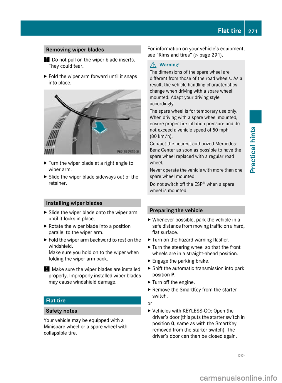
Removing wiper blades
! Do not pull on the wiper blade inserts.
They could tear.
X Fold the wiper arm forward until it snaps
into place. X
Turn the wiper blade at a right angle to
wiper arm.
X Slide the wiper blade sideways out of the
retainer. Installing wiper blades
X Slide the wiper blade onto the wiper arm
until it locks in place.
X Rotate the wiper blade into a position
parallel to the wiper arm.
X Fold the wiper arm backward to rest on the
windshield.
Make sure you hold on to the wiper when
folding the wiper arm back.
! Make sure the wiper blades are installed
properly. Improperly installed wiper blades
may cause windshield damage. Flat tire
Safety notes
Your vehicle may be equipped with a
Minispare wheel or a spare wheel with
collapsible tire. For information on your vehicle’s equipment,
see “Rims and tires” (
Y page 291). G
Warning!
The dimensions of the spare wheel are
different from those of the road wheels. As a
result, the vehicle handling characteristics
change when driving with a spare wheel
mounted. Adapt your driving style
accordingly.
The spare wheel is for temporary use only.
When driving with a spare wheel mounted,
ensure proper tire inflation pressure and do
not exceed a vehicle speed of 50 mph
(80 km/h).
Contact the nearest authorized Mercedes-
Benz Center as soon as possible to have the
spare wheel replaced with a regular road
wheel.
Never operate the vehicle with more than one
spare wheel mounted.
Do not switch off the ESP ®
when a spare
wheel is mounted. Preparing the vehicle
X Whenever possible, park the vehicle in a
safe distance from moving traffic on a hard,
flat surface.
X Turn on the hazard warning flasher.
X Turn the steering wheel so that the front
wheels are in a straight-ahead position.
X Engage the parking brake.
X Shift the automatic transmission into park
position P.
X Turn off the engine.
X Remove the SmartKey from the starter
switch.
or
X Vehicles with KEYLESS-GO: Open the
driver’s door (this puts the starter switch in
position 0, same as with the SmartKey
removed from the starter switch). The
driver’s door can then be closed again. Flat tire
271Practical hints
219_AKB; 4; 54, en-US
d2ureepe, Version: 2.11.8.1 2009-05-11T16:21:02+02:00 - Seite 271 Z
Page 274 of 308
Open doors only when conditions are safe
to do so.
X Have any passenger exit the vehicle at a
safe distance from the roadway. Open
doors only when conditions are safe to do
so. Mounting the spare wheel
Introduction X
Prepare the vehicle as described
(Y page 271).
X Take the following out of the vehicle:
R
spare wheel
R jack
R vehicle tool kit
R wheel wrench
R electric air pump (required for vehicles
with spare wheel with collapsible tire
only)
For information on where to find the
respective items, see “Where will I find ...?”
(Y page 224) and ( Y page 226).
i Vehicles without spare wheel are not
factory-equipped with the tools required for
a wheel change such as a jack or a wheel
wrench. Some tools required for a wheel
change are specific to your vehicle.
Contact an authorized Mercedes-Benz
Center to obtain the tools approved for
your vehicle. This section describes the
wheel change using the tools approved and
recommended for your vehicle.
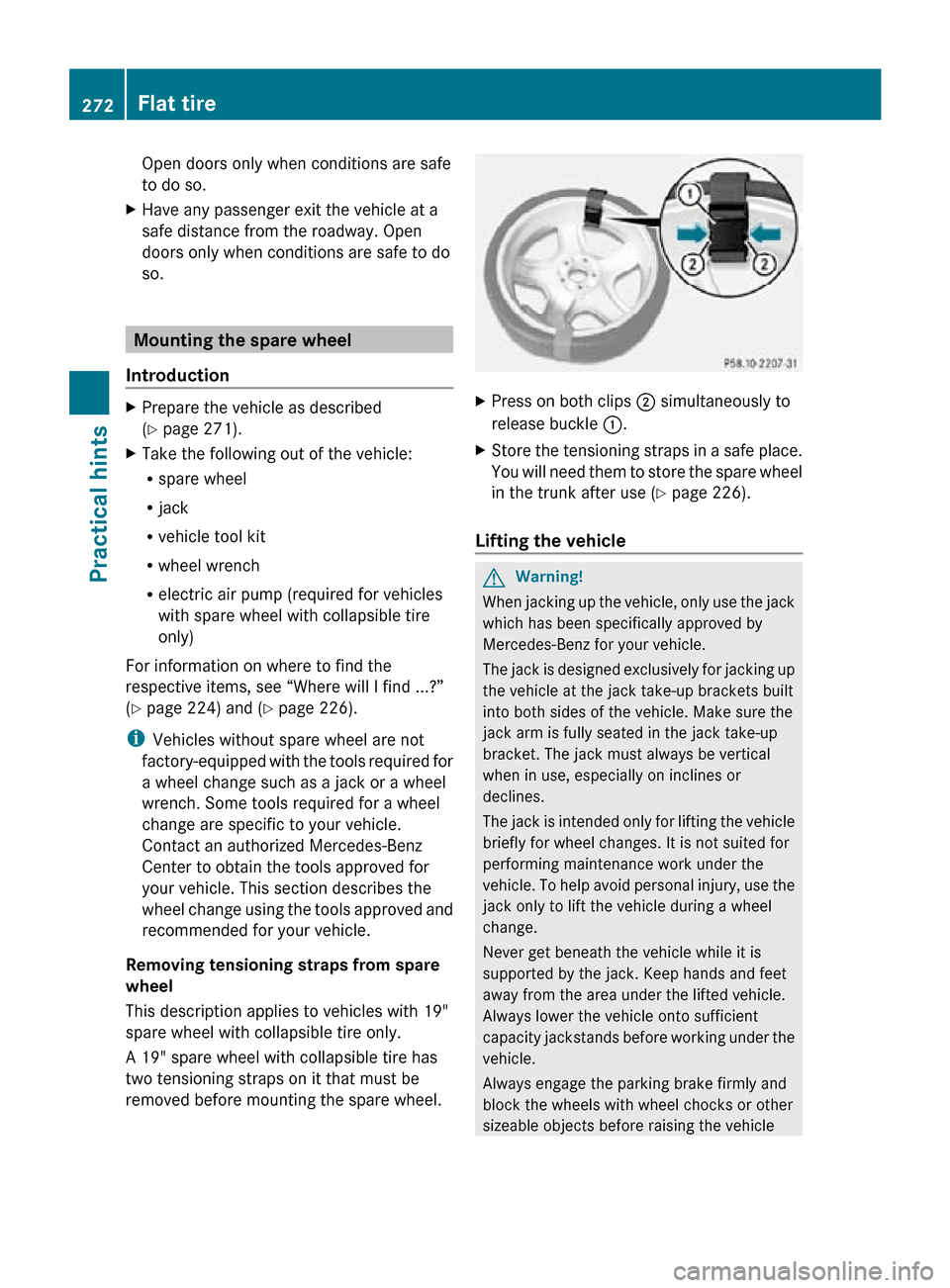
Removing tensioning straps from spare
wheel
This description applies to vehicles with 19"
spare wheel with collapsible tire only.
A 19" spare wheel with collapsible tire has
two tensioning straps on it that must be
removed before mounting the spare wheel. X
Press on both clips ; simultaneously to
release buckle :.
X Store the tensioning straps in a safe place.
You will need them to store the spare wheel
in the trunk after use (Y page 226).
Lifting the vehicle G
Warning!
When jacking up the vehicle, only use the jack
which has been specifically approved by
Mercedes-Benz for your vehicle.
The jack is designed exclusively for jacking up
the vehicle at the jack take-up brackets built
into both sides of the vehicle. Make sure the
jack arm is fully seated in the jack take-up
bracket. The jack must always be vertical
when in use, especially on inclines or
declines.
The jack is intended only for lifting the vehicle
briefly for wheel changes. It is not suited for
performing maintenance work under the
vehicle. To help avoid personal injury, use the
jack only to lift the vehicle during a wheel
change.
Never get beneath the vehicle while it is
supported by the jack. Keep hands and feet
away from the area under the lifted vehicle.
Always lower the vehicle onto sufficient
capacity jackstands before working under the
vehicle.
Always engage the parking brake firmly and
block the wheels with wheel chocks or other
sizeable objects before raising the vehicle 272
Flat tirePractical hints
219_AKB; 4; 54, en-US
d2ureepe,
Version: 2.11.8.1 2009-05-11T16:21:02+02:00 - Seite 272
Page 275 of 308
with the jack. Do not disengage the parking
brake while the vehicle is raised.
Make sure that the ground on which the
vehicle is standing and where you place the
jack is solid, level and not slippery. If
necessary, use a large underlay. On slippery
surfaces, such as tiled floors, you should use
a non-slip underlay, for example a rubber mat.
Do not use wooden blocks or similar objects
to support the jack. Otherwise the jack may
not be able to achieve its load-bearing
capacity if it is not at its full height.
Never start the engine when the vehicle is
raised.
Also observe the notes on the jack.
X Prevent the vehicle from rolling away by
blocking wheels with wheel chocks or other
sizeable objects.
When your vehicle is equipped with a wheel
chock, it is included with the vehicle tool kit
(Y page 224). For information on setting up
the collapsible wheel chock, see
(Y page 225).
When changing a wheel on a level surface:
X Place a wheel chock or other sizeable
object in front of and another wheel chock
or other sizeable object behind the wheel
that is diagonally opposite to the wheel
being changed.
Always try lifting the vehicle using the jack on
a level surface. However, should
circumstances require you to do so on a hill:
X Place wheel chocks or other sizeable
objects on the downhill side in front of both
wheels on the side opposite to the side on
which the wheel is to be changed. G
Warning!
Only jack up the vehicle on level ground or on
slight inclines/declines. Otherwise, the
vehicle could fall off the jack and injure you or
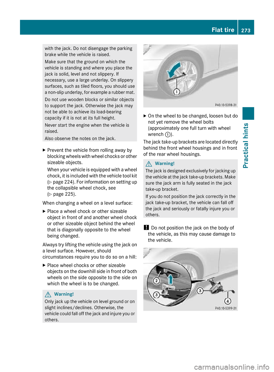
others. X
On the wheel to be changed, loosen but do
not yet remove the wheel bolts
(approximately one full turn with wheel
wrench :).
The jack take-up brackets are located directly
behind the front wheel housings and in front
of the rear wheel housings. G
Warning!
The jack is designed exclusively for jacking up
the vehicle at the jack take-up brackets. Make
sure the jack arm is fully seated in the jack
take-up bracket.
If you do not position the jack correctly in the
jack take-up bracket, the vehicle can fall off
the jack and seriously or fatally injure you or
others.
! Do not position the jack on the body of
the vehicle, as this may cause damage to
the vehicle. Flat tire
273Practical hints
219_AKB; 4; 54, en-US
d2ureepe, Version: 2.11.8.1 2009-05-11T16:21:02+02:00 - Seite 273 Z
Page 276 of 308
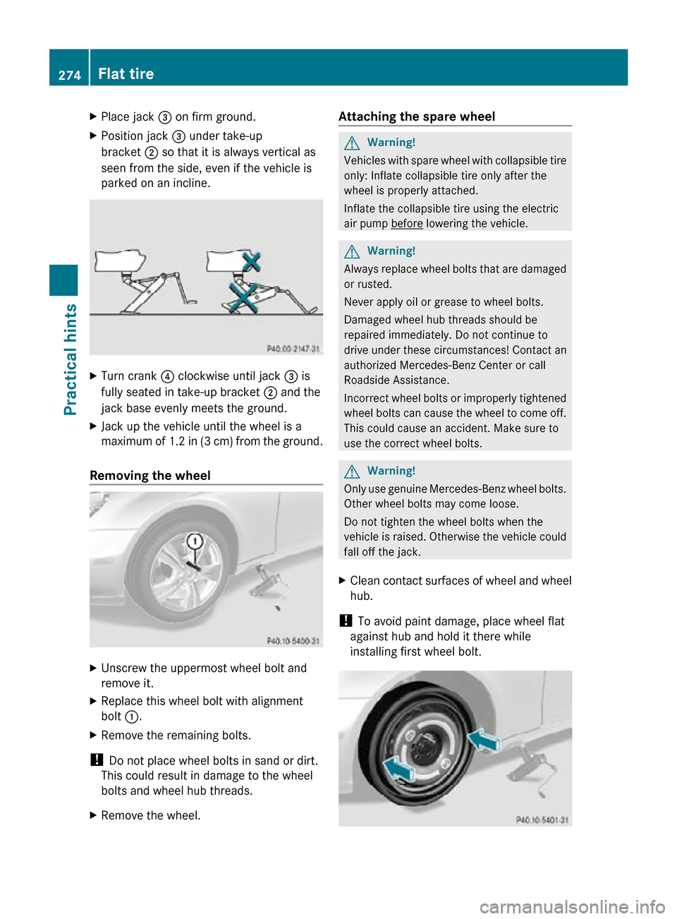
X
Place jack = on firm ground.
X Position jack = under take-up
bracket ; so that it is always vertical as
seen from the side, even if the vehicle is
parked on an incline. X
Turn crank ? clockwise until jack = is
fully seated in take-up bracket ; and the
jack base evenly meets the ground.
X Jack up the vehicle until the wheel is a
maximum of 1.2 in (3 cm) from the ground.
Removing the wheel X
Unscrew the uppermost wheel bolt and
remove it.
X Replace this wheel bolt with alignment
bolt :.
X Remove the remaining bolts.
! Do not place wheel bolts in sand or dirt.
This could result in damage to the wheel
bolts and wheel hub threads.
X Remove the wheel. Attaching the spare wheel G
Warning!
Vehicles with spare wheel with collapsible tire
only: Inflate collapsible tire only after the
wheel is properly attached.
Inflate the collapsible tire using the electric
air pump before lowering the vehicle.
G
Warning!
Always replace wheel bolts that are damaged
or rusted.
Never apply oil or grease to wheel bolts.
Damaged wheel hub threads should be
repaired immediately. Do not continue to
drive under these circumstances! Contact an
authorized Mercedes-Benz Center or call
Roadside Assistance.
Incorrect wheel bolts or improperly tightened
wheel bolts can cause the wheel to come off.
This could cause an accident. Make sure to
use the correct wheel bolts. G
Warning!
Only use genuine Mercedes-Benz wheel bolts.
Other wheel bolts may come loose.
Do not tighten the wheel bolts when the
vehicle is raised. Otherwise the vehicle could
fall off the jack.
X Clean contact surfaces of wheel and wheel
hub.
! To avoid paint damage, place wheel flat
against hub and hold it there while
installing first wheel bolt. 274
Flat tirePractical hints
219_AKB; 4; 54, en-US
d2ureepe,
Version: 2.11.8.1 2009-05-11T16:21:02+02:00 - Seite 274
Page 277 of 308
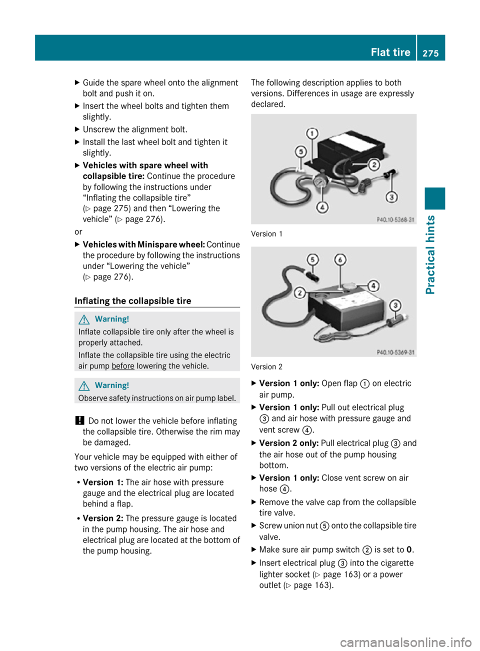
X
Guide the spare wheel onto the alignment
bolt and push it on.
X Insert the wheel bolts and tighten them
slightly.
X Unscrew the alignment bolt.
X Install the last wheel bolt and tighten it
slightly.
X Vehicles with spare wheel with
collapsible tire: Continue the procedure
by following the instructions under
“Inflating the collapsible tire”
(Y page 275) and then “Lowering the
vehicle” ( Y page 276).
or
X Vehicles with Minispare wheel: Continue
the procedure by following the instructions
under “Lowering the vehicle”
(Y page 276).
Inflating the collapsible tire G
Warning!
Inflate collapsible tire only after the wheel is
properly attached.
Inflate the collapsible tire using the electric
air pump before lowering the vehicle.
G
Warning!
Observe safety instructions on air pump label.
! Do not lower the vehicle before inflating
the collapsible tire. Otherwise the rim may
be damaged.
Your vehicle may be equipped with either of
two versions of the electric air pump:
R Version 1: The air hose with pressure
gauge and the electrical plug are located
behind a flap.
R Version 2: The pressure gauge is located
in the pump housing. The air hose and
electrical plug are located at the bottom of
the pump housing. The following description applies to both
versions. Differences in usage are expressly
declared.
Version 1
Version 2
X
Version 1 only: Open flap : on electric
air pump.
X Version 1 only: Pull out electrical plug
= and air hose with pressure gauge and
vent screw ?.
X Version 2 only: Pull electrical plug = and
the air hose out of the pump housing
bottom.
X Version 1 only: Close vent screw on air
hose ?.
X Remove the valve cap from the collapsible
tire valve.
X Screw union nut A onto the collapsible tire
valve.
X Make sure air pump switch ; is set to 0.
X Insert electrical plug = into the cigarette
lighter socket ( Y page 163) or a power
outlet (Y page 163). Flat tire
275Practical hints
219_AKB; 4; 54, en-US
d2ureepe, Version: 2.11.8.1 2009-05-11T16:21:02+02:00 - Seite 275 Z
Page 278 of 308
X
Turn the SmartKey in the starter switch to
position 1.
or
X Vehicles with KEYLESS-GO: Press the
KEYLESS-GO start/stop button once. Do
not depress the brake pedal.
X Press I on electric air pump switch ;.
The electric air pump switches on and
inflates the collapsible tire.
X Inflate the collapsible tire to the
recommended tire inflation pressure as
specified for your vehicle ( Y page 296).
This should take approximately 5 minutes. G
Warning!
The air hose and the union nut can become
hot during inflation. Exercise proper caution
to avoid burning yourself when using the
equipment.
! Do not operate the electric air pump
longer than 8 minutes without interruption.
Otherwise it may overheat.
You may operate the air pump again after
it has cooled off.
! Compare the recommended tire inflation
pressure for your vehicle with the tire
inflation pressure on the yellow label
located on the spare wheel rim.
If the tire inflation pressure on the yellow
label on the spare wheel rim differs from
the values given in this Operator’s Manual,
inflate the tire to the recommended tire
inflation pressure given on the yellow label
on the spare wheel rim.
X Press 0 on electric air pump switch ;.
X Turn the SmartKey in the starter switch to
position 0.
or
X Vehicles with KEYLESS-GO: Press the
KEYLESS-GO start/stop button twice. Do
not depress the brake pedal.
X Version 1 only: If the tire inflation pressure
is above the recommended tire inflation pressure as specified for your vehicle
(Y page 296), decrease tire pressure using
the vent screw on air hose ?.
X Version 2 only: If the tire inflation pressure
is above the recommended tire inflation
pressure as specified for your vehicle
(Y page 296), decrease tire pressure using
deflate button B. G
Observe Safety notes, see page 185.
X Detach the electric air pump.
X Reinstall collapsible tire valve cap.
X Version 1 only: Store electrical plug =
and air hose ? behind flap :.
X Version 2 only: Store electrical plug =
and the air hose back into the pump
housing bottom.
X Place the electric air pump back in its
designated storage space.
X Lower the vehicle.
Lowering the vehicle G
Warning!
Vehicles with spare wheel with collapsible tire
only: Inflate collapsible tire only after the
wheel is properly attached.
Inflate the collapsible tire using the electric
air pump before lowering the vehicle.
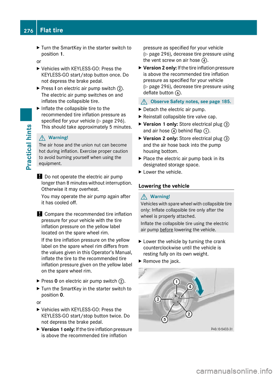
X Lower the vehicle by turning the crank
counterclockwise until the vehicle is
resting fully on its own weight.
X Remove the jack. 276
Flat tirePractical hints
219_AKB; 4; 54, en-US
d2ureepe,
Version: 2.11.8.1 2009-05-11T16:21:02+02:00 - Seite 276
Page 279 of 308
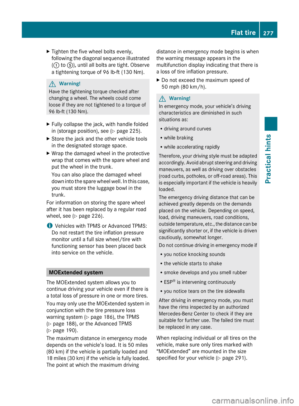
X
Tighten the five wheel bolts evenly,
following
the diagonal sequence illustrated
(: to A), until all bolts are tight. Observe
a tightening torque of 96 lb-ft (130 Nm). G
Warning!
Have the tightening torque checked after
changing a wheel. The wheels could come
loose if they are not tightened to a torque of
96 lb-ft (130 Nm).
X Fully collapse the jack, with handle folded
in (storage position), see
(Y page 225).
X Store the jack and the other vehicle tools
in the designated storage space.
X Wrap the damaged wheel in the protective
wrap
that comes with the spare wheel and
put the wheel in the trunk.
You can also place the damaged wheel
down into the spare wheel well. In this case,
you must store the luggage bowl in the
trunk.
For information on storing the spare wheel
after it has been replaced by a regular road
wheel, see
(Y page 226).
i Vehicles with TPMS or Advanced TPMS:
Do not restart the tire inflation pressure
monitor until a full size wheel/tire with
functioning sensor has been placed back
into service on the vehicle. MOExtended system
The MOExtended system allows you to
continue driving your vehicle even if there is
a total loss of pressure in one or more tires.
You
may only use the MOExtended system in
conjunction with the tire pressure loss
warning system ( Y page 186), the TPMS
(Y page 188), or the Advanced TPMS
(Y page 190).
The maximum distance in emergency mode
depends on the vehicle’s load. It is 50 miles
(80 km) if the vehicle is partially loaded and
18 miles (30 km) if the vehicle is fully loaded.
The point at which the maximum driving distance in emergency mode begins is when
the warning message appears in the
multifunction display indicating that there is
a loss of tire inflation pressure.
X
Do not exceed the maximum speed of
50 mph (80 km/h
). G
Warning!
In emergency mode, your vehicle’s driving
characteristics are diminished in such
situations as:
R driving around curves
R while braking
R while accelerating rapidly
Therefore,
your driving style must be adapted
accordingly. Avoid abrupt steering and driving
maneuvers, as well as driving over obstacles
(road curbs, potholes, or off-road areas). This
is especially important if the vehicle is heavily
loaded.
The emergency driving distance that can be
achieved greatly depends on the demands
placed on the vehicle. Depending on speed,
load, driving maneuvers, road conditions,
outside temperature, etc., the distance can be
significantly shorter or, if the vehicle is driven
cautiously, somewhat longer.
Do not continue driving in emergency mode if
R you notice knocking sounds
R the vehicle starts to shake
R smoke develops and you smell rubber
R ESP ®
is intervening continuously
R you notice tears on the tire sidewalls
After driving in emergency mode, you must
have the rims inspected by an authorized
Mercedes-Benz Center to check if they are
suitable for further use. The failed tire must
be replaced in any case.
When replacing individual or all tires on the
vehicle, make sure only tires marked with
“MOExtended” are mounted in the size
specified for your vehicle ( Y page 291). Flat tire
277
Practical hints
219_AKB; 4; 54, en-US
d2ureepe, Version: 2.11.8.1 2009-05-11T16:21:02+02:00 - Seite 277 Z
Page 280 of 308
Battery
Safety notes
A battery should always be sufficiently
charged in order to achieve its rated service
life. Refer to Maintenance Booklet for battery
maintenance intervals.
If you use your vehicle mostly for short-
distance trips, you will need to have the
battery charge checked more frequently.
When replacing a battery, always use a
battery approved by Mercedes-Benz.
If you do not intend to operate your vehicle
for an extended period of time, contact an
authorized Mercedes-Benz Center about
steps you need to observe. G
Warning!
Observe all safety instructions and
precautions when handling automotive
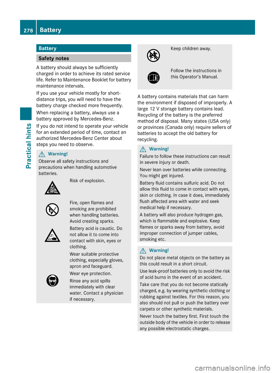
batteries.Risk of explosion.
Fire, open flames and
smoking are prohibited
when handling batteries.
Avoid creating sparks.
Battery acid is caustic. Do
not allow it to come into
contact with skin, eyes or
clothing.
Wear suitable protective
clothing, especially gloves,
apron and faceguard.
Wear eye protection.
Rinse any acid spills
immediately with clear
water. Contact a physician
if necessary.
Keep children away.
Follow the instructions in
this Operator’s Manual.
A battery contains materials that can harm
the environment if disposed of improperly. A
large 12 V storage battery contains lead.
Recycling of the battery is the preferred
method of disposal. Many states (USA only)
or provinces (Canada only) require sellers of
batteries to accept the old battery for
recycling.
G Warning!
Failure to follow these instructions can result
in severe injury or death.
Never lean over batteries while connecting.
You might get injured.
Battery fluid contains sulfuric acid. Do not
allow this fluid to come in contact with eyes,
skin or clothing. In case it does, immediately
flush affected area with water and seek
medical help if necessary.
A battery will also produce hydrogen gas,
which is flammable and explosive. Keep
flames or sparks away from battery, avoid
improper connection of jumper cables,
smoking etc.
G Warning!
Do not place metal objects on the battery as
this could result in a short circuit.
Use leak-proof batteries only to avoid the risk
of acid burns in the event of an accident.
Take care that you do not become statically
charged, e.g. by wearing synthetic clothing or
rubbing against textiles. For this reason, you
also should not pull or push the battery over
carpets or other synthetic materials.
Never touch the battery first. First touch the
outside body of the vehicle in order to release
any possible electrostatic charges.
278 Battery
Practical hints
219_AKB; 4; 54, en-US
d2ureepe,
Version: 2.11.8.1 2009-05-11T16:21:02+02:00 - Seite 278