sensor MERCEDES-BENZ E-Class 2001 W210 Owner's Manual
[x] Cancel search | Manufacturer: MERCEDES-BENZ, Model Year: 2001, Model line: E-Class, Model: MERCEDES-BENZ E-Class 2001 W210Pages: 421, PDF Size: 20.52 MB
Page 7 of 421

4 Contents
Instrument cluster displayMalfunction and indicator
lamps in the
instrument cluster ....................296
On-board diagnostic system .....296
Check engine malfunction
indicator lamp .............................296
Brake warning lamp ..................298
Supplemental restraint
system (SRS)
indicator lamp .............................299
Fuel reserve warning .................299
ABS malfunction
indicator lamp .............................300
Electronic stability
program (ESP) —
warning lamp ..............................301
Distronic (DTR) –
warning lamp ..............................301
Seat belt nonusage
warning lamp ..............................302Malfunction and
indicator lamp in the
center console ........................... 302
AIRBAG OFF indicator lamp .... 302
Malfunction and
warning messages in the
multifunction display .............. 303
DISPLAY DEFECTIVE ................ 304
BATTERY/ALTERNATOR .......... 305
ENTRANCE POSITION .............. 306
BRAKE ASSIST ........................... 306
BRAKE LINING WEAR .............. 307
BRAKE FLUID ............................ 307
PARKING BRAKE ....................... 308
TRUNK OPEN ............................. 308
ELEC. STABIL. PROG.
(Electronic stability
program) ..................................... 309
COOLANT (coolant level) .......... 310
COOLANT
(coolant temperature) ................ 311LIGHTING SYSTEM .................... 312
LIGHT SENSOR ........................... 314
ACTIV E BO DY CO NTROL
(ABC) ............................................ 314
TIRE PRESSURE ......................... 316
ENGINE OIL LEVEL ................... 318
CRUISE CONTROL ..................... 319
KEY ............................................... 319
DOOR ...........................................320
HOOD ...........................................320
TELE AID .....................................321
OIL TEMP.
(engine oil temperature) ...........321
CHIP-CARD (KEYLESS-GO) ......322
SELECTOR LEVER ......................323
TELEPHONE – FUNCTION .......323
WASHER FLUID .........................324
AIR SPRING (AirMatic) .............325
DISTRONIC (DTR) ......................326
Page 8 of 421

5 Contents
Practical hintsFirst aid kit .....................................328
Stowing things in the vehicle ......328
Fuses ................................................329
Hood ................................................. 331
Checking engine oil level .............334
Automatic transmission
fluid level ...................................335
Active body control
(ABC) fluid level ........................335
Coolant level ...................................336
Adding coolant ...........................336
Windshield and
headlamp washer system ........337
Windshield and
headlamp washer fluid
mixing ratio ................................337
Spare wheel, vehicle tools,
storage compartment ................338
Vehicle jack .....................................339
Wheels .............................................340
Tire Replacement .......................340
Rotating wheels .......................... 341
Spare wheel .................................... 341Changing wheels ........................... 343
Tire inflation pressure ................. 348
Battery ............................................. 349
Jump starting ................................. 351
Towing the vehicle ........................ 353
Exterior lamps ............................... 356
Headlamp assembly .................. 357
Taillamp assemblies .................. 360
Trunk lamp ..................................... 362
Changing batteries in the
electronic main key .................. 363
Synchronizing
remote control ............................ 365
Changing batteries in the
KEYLESS-GO-card .................... 366
Emergency engine
shut-down .................................. 368
Fuel filler flap,
manual release ......................... 368
Emergency operation of
sliding/pop-up roof .................. 369
Replacing wiper blades ................ 370
Roof rack ..........................................371
Vehicle careCleaning and care
of the vehicle ............................. 374
Power washer ..............................375
Tar stains ..................................... 376
Paintwork, painted body
components ................................. 376
Engine cleaning .......................... 376
Vehicle washing ......................... 376
Ornamental moldings ................377
Headlamps, taillamps,
turn signal lenses ......................377
Cleaning the Distronic
system sensor .............................378
Cleaning the parktronic
system sensors ...........................378
Wiper blades ...............................379
Light alloy wheels ......................380
Instrument cluster .....................380
Steering wheel and
gear selector lever ......................380
Cup holder ...................................380
Seat belts ..................................... 381
Page 98 of 421
95 Restraint systems
Te ch n ica l
data Instruments
and controlsOperationDrivingInstrument
cluster displayPractical hints Car care Index come on at all or if it fails to extinguish after
approximately 4 seconds or if it comes on thereafter, a
malfunction in the system has been detected.
The following system components are monitored or
undergo a self-check: crash-sensor(s), airbag ignition
circuits, front seat belt buckles, emergency tensioning
retractors, seat sensor.
Initially, when the electronic key is turned from starter
switch position 0 to position 1 or 2, malfunctions in the
crash sensor are detected and indicated (the “SRS”
indicator lamp stays on longer than 4 seconds or does
not come on).
Have the system checked at your authorized
Mercedes-Benz Center immediately.
In the operational mode, after the indicator lamp has
gone out following the initial check, interruptions or
short circuits in the airbag ignition circuit and in the
driver and front passenger seat belt buckle harnesses,
and low voltage in the entire system are detected and
indicated.Note:
See page 299 for information on the Supplemental
Restraint System (SRS) indicator lamp.
The driver and passenger front airbags are designed to
activate only in certain frontal impacts exceeding a
preset threshold. The front passenger airbag deploys
only if the front passenger seat is occupied and the
7 indicator lamp on the center console is not
illuminated.
Note:
Heavy objects on the front passenger seat can appear to
the “SRS” to indicate the presence of an occupant in
that seat which causes the passenger front airbag to
deploy in a crash exceeding the appropriate threshold.
Wa r n i n g !
In the event a malfunction of the “SRS” is indicated
as outlined above, the “SRS” may not be
operational. For your safety, we strongly recommend
that you visit an authorized Mercedes-Benz Center
immediately to have the system checked; otherwise the
“SRS” may not be activated when needed in an
accident, which could result in serious or fatal injury,
or it might deploy unexpectedly and unnecessarily
which could also result in injury.
Page 109 of 421
106 Rear view mirrors
Te ch n ica l
data Instruments
and controlsOperationDrivingInstrument
cluster displayPractical hints Car care Index
Rear view mirrors
Inside rear view mirror
Manually adjust the mirror.
Storing interior rear view mirror positions
The seat, exterior rear view mirror and steering wheel
positions are stored together with the interior rear view
mirror position. See page 111 for notes on the memory
function.
Rear view mirror, automatic antiglare
Antiglare mode:
With the electronic key in starter switch position 2, the
mirror reflection brightness responds to changes in
light sensitivity.
With the gear selection lever in position “R”, or with the
interior light switched on, the mirror brightness does
not respond to changes in light sensitivity.Note:
The automatic antiglare function does not react, if
incoming light is not aimed directly at sensors in the
mirror.
Wa r n i n g !
In the case of an accident liquid electrolyte may
escape the mirror housing when the mirror glass
breaks.Electrolyte has an irritating effect. Do not allow the
liquid come into contact with eyes, skin, clothing,
or respiratory system. In cases it does, immediately
flush affected area with water, and seek medical
help if necessary.
Page 113 of 421
110 Rear view mirrors
Te ch n ica l
data Instruments
and controlsOperationDrivingInstrument
cluster displayPractical hints Car care Index
Driver’s side exterior mirror, antiglare mode
Antiglare mode:
With the electronic key in starter switch position 2, the
mirror reflection brightness responds to changes in
light sensitivity.
With the gear selector lever in position “R”, or with the
interior light switched on, the mirror brightness does
not respond to changes in light sensitivity.
Note:
The automatic antiglare function does not react, if
incoming light is not aimed directly at sensors in the
mirror.Important!
Electrolyte drops coming into contact with the vehicle
paint finish can only be completely removed while in
their liquid state, by applying plenty of water.
Wa r n i n g !
In the case of an accident liquid electrolyte may
escape the mirror housing when the mirror glass
breaks.Electrolyte has an irritating effect. Do not allow the
liquid come into contact with eyes, skin, clothing,
or respiratory system. In cases it does, immediately
flush affected area with water, and seek medical
help if necessary.
Page 120 of 421
117 Instrument cluster
Te ch n ica l
data Instruments
and controlsOperationDrivingInstrument
cluster displayPractical hints Car care Index Coolant temperature gauge (5)
During severe operating conditions and stop-and-go city
traffic, the coolant temperature may rise close to the red
marking.
The engine should not be operated with the coolant
temperature in the red zone. Doing so may cause
serious engine damage which is not covered by the
Mercedes-Benz Limited Warranty.Outside temperature indicator (6)
The temperature sensor is located in the front bumper
area. Due to its location, the sensor can be affected by
road or engine heat during idling or slow driving. This
means that the accuracy of the displayed temperature
can only be verified by comparison to a thermometer
placed next to the sensor, not by comparison to external
displays (e.g. bank signs etc.).
Adaption to ambient temperature takes place in steps
and depends on the prevailing driving conditions (stop-
and-go or moderate, constant driving) and amount of
temperature change.
Note:
The temperature indicator display can be set to read out
in either Fahrenheit or Celsius. See page 138.
Wa r n i n g !
• Driving when your engine is badly overheated
can cause some fluids which may have leaked
into the engine compartment to catch fire. You
could be seriously burned.• Steam from an overheated engine can cause
serious burns and can occur just by opening
the engine hood. Stay away from the engine if
you see or hear steam coming from it. Turn off
the engine, get out of the vehicle and do not
stand near the vehicle until it cools down.
Wa r n i n g !
The outside temperature indicator is not designed
to serve as an Ice-Warning Device and is therefore
unsuitable for that purpose. Indicated
temperatures just above the freezing point do not
guarantee that the road surface is free of ice.
Page 156 of 421
153 Tire inflation pressure monitor
Te ch n ica l
data Instruments
and controlsOperationDrivingInstrument
cluster displayPractical hints Car care Index Notes:
To ensure proper functioning of the tire inflation
pressure monitor, the tire inflation pressure should be
checked and corrected according to the label affixed
inside the fuel filler flap. For a detailed description,
refer to page 348.
The message “TYRE PRESS. CONTROL – REACTIVATE”
appears if the tire inflation pressure shows an increase
of 4.4 psi (0.3 bar) or more. Reactivate the tire inflation
pressure monitor.
The tire inflation pressure monitor only functions on
wheels equipped with the proper electronic sensors.
Inquire at your authorized Mercedes-Benz Center about
retrofitting other than original Mercedes-Benz wheels
with electronic sensors.Transporting a deflated road wheel in the vehicle, e.g.
after having a flat, the tire inflation pressure monitor
should only be activated once the flat tire and rim are
removed from the vehicle. Otherwise the monitor
displays the message “TYRE PRESS. CONTROL –
CURRENTLY INACTIVE”.
To prevent possible damage to the electronic sensors,
have tire changes only performed at an authorized
Mercedes-Benz Center.
For malfunction and warning messages, see page 303.
Page 164 of 421
161 Combination switch
Te ch n ica l
data Instruments
and controlsOperationDrivingInstrument
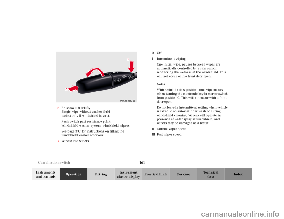
cluster displayPractical hints Car care Index 6Press switch briefly:
Single wipe without washer fluid
(select only if windshield is wet).
Push switch past resistance point:
Windshield washer system, windshield wipers.
See page 337 for instructions on filling the
windshield washer reservoir.
7Windshield wipers0Off
I Intermittent wiping
One initial wipe, pauses between wipes are
automatically controlled by a rain sensor
monitoring the wetness of the windshield. This
will not occur with a front door open.
Notes:
With switch in this position, one wipe occurs
when turning the electronic key in starter switch
from position 0. This will not occur with a front
door open.
Do not leave in intermittent setting when vehicle
is taken to an automatic car wash or during
windshield cleaning. Wipers will operate in
presence of water spray at windshield, and
wipers may be damaged as a result.
II Normal wiper speed
III Fast wiper speed
P54.25-2389-26
6
7
Page 227 of 421
224 Catalytic converter
Te ch n ica l
data Instruments
and controlsOperationDrivingInstrument
cluster displayPractical hints Car care Index
Catalytic converter
Your Mercedes-Benz is equipped with monolithic type
catalytic converters, an important element in
conjunction with the oxygen sensors to achieve
substantial control of the pollutants in the exhaust
emissions. Keep your vehicle in proper operating
condition by following our recommended maintenance
instructions as outlined in your Service Booklet.
Caution!
To prevent damage to the catalytic converters, use only
premium unleaded gasoline in this vehicle.
Any noticeable irregularities in engine operation should
be repaired promptly. Otherwise, excessive unburned
fuel may reach the catalytic converter causing it to
overheat, which could start a fire.
Wa r n i n g !
As with any vehicle, do not idle, park or operate
this vehicle in areas where combustible materials
such as grass, hay or leaves can come into contact
with the hot exhaust system, as these materials
could be ignited and cause a vehicle fire.
Page 259 of 421
256 Driving systems
Te ch n ica l
data Instruments
and controlsOperationDrivingInstrument
cluster displayPractical hints Car care Index
Distronic (DTR)
(optional)
When activated the Distronic system increases driving
convenience, for example over long distances, as it
automatically maintains a speed set by the driver by
actively regulating the throttle setting. It also maintains
within certain limitations a preset distance to a vehicle
ahead.
With Distronic switched off, the multifunction display
continues to show the distance to the vehicle ahead, if
so selected, see page 269.
The distance notification function can be activated
separately, see page 267.
In Distronic mode, if the distance sensor detects a
slower moving vehicle directly ahead, your vehicle
speed will be reduced to the extent permitted by
reduced throttle and up to 20% of vehicle braking power,
so that you follow that vehicle at a preset distance, see
page 268.
Maximum range of detection is approximately 500 ft.
(150 m).Any given speed between 25 mph (Canada: 30 km/h)
and 110 mph (Canada: 180 km/h) can be maintained
with the Distronic by operating the control lever on the
steering column.
Wa r n i n g !
Distronic is a convenience system, its speed
adjustment reduction capability is intended to
make cruise control more effective and usable
when traffic speeds vary. It is not, however,
intended to nor does it replace the need for extreme
care. The responsibility for the vehicle speed and
the distance to the vehicle ahead, including most
importantly brake operation to assure safe stopping
distance, rests always with the driver.Wa r n i n g !
Distronic requires familiarity with its operational
characteristics. We strongly recommend that you
review the following information carefully before
operating the system.