warning light MERCEDES-BENZ E-Class CABRIOLET 2014 C207 Owners Manual
[x] Cancel search | Manufacturer: MERCEDES-BENZ, Model Year: 2014, Model line: E-Class CABRIOLET, Model: MERCEDES-BENZ E-Class CABRIOLET 2014 C207Pages: 394, PDF Size: 5.28 MB
Page 307 of 394
X
To start route guidance: selectYes .
An overview of the route is shown in the
display.
i If you select No , the saved route can be
called up later via the navigation menu.
X Select Start .
Route guidance is started.
i Downloaded and saved data can be called
up agai ninCOMAND.
You can find further information in the
separate COMAND Operating Instructions.
Speed alert You can define the upper speed limit, which
must not be exceeded by the vehicle.
If this selected speed is exceeded by the
vehicle, a message will be sent to the
Customer Assistance center. The Customer
Assistance center then forwards this
information to you.
You can select the way in which you receive
this information beforehand. Possible options
include text message, e-mail or an automated
call.
The data you receive contains the following
information:
R the location where the speed limit was
exceeded
R the time at which the speed limit was
exceeded
R the selected speed limit which was
exceeded
Geo fencing Geo fencing allows you to select areas which
the vehicle should not enter or leave. You will
be informed if the vehicle crosses the
boundaries of the selected areas. You can
select the way in which you receive this
information beforehand. Possible options
include text message, e-mail or an automated
call.
The area can be determined as either a circle
or a polygon with a maximum of ten corners. You can specify up to ten areas
simultaneously. Different settings are
possible for each area.
USA only: these settings can be called up
under "Owners Online" at http://
www.mbusa.com.
Alternatively, you can trigger an MB Info call
and inform the customer service
representative that you wish to activate geo
fencing.
Currently inactive areas can be activated by
text message.
Triggering the vehicle alarm With this function, you can trigger the
vehicle's panic alarm via text message. An
alarm sounds and the exterior lighting
flashes. Depending on the setting, the panic
alarm lasts five or ten seconds. Afterwards,
the alarm switches off.
Garage door opener
Important safety notes G
WARNING
When you operate or program the garage door
with the integrated garage door opener,
persons in the range of movement of the
garage door can become trapped or struck by
the garage door. There is arisk of injury.
When using the integrated garage door
opener, always make sure that nobody is
within the range of movement of the garage
door. G
WARNING
Combustion engines emit poisonous exhaust
gases such as carbo nmonoxide. Inhaling
these exhaust gases leads to poisoning. There
is a risk of fatal injury. Therefore never leave
the engine running in enclosed spaces
without sufficient ventilation.
The HomeLink ®
garage door opener
integrated in the rear-view mirror allows you Features
305Stowage and features Z
Page 310 of 394
The integrated garage door opener is
compatible with devices that have units
which operate in the frequency range of
280to 433MHz.
R Replace the batteries in garage door
remote control 0020.This increases the
likelihood that garage door remote control
0020 will transmit a stronga nd precise signal
to the integrated garage door opene rinthe
rear-view mirror.
R When programming, hold remote control
0020 at varying distances and angles from the
button that you are programming. Try
various angles at a distance between 2and
12 inches (5to 30 cm) or at the same angle
but at varying distances.
R If another remote control for the same
garage door drive is available, repeat the
same programming steps with this remote
control. Before performing these steps,
make sure that new batteries have been
installed in garage door drive remote
control 0020.
R Note that some remote controls only
transmit for a limited amount of time (the
indicator lamp on the remote control goes
out). Press button 0021on remote control
0020 again before transmission ends.
R Align the antenna cable of the garage door
opener unit. This can improve signal
reception/transmission.
Opening/closing the garage door After it has been programmed, the integrated
garage door opener performs the function of
the garage door system remote control.
Please also read the operating instructions
for the garage door system.
X
Turn the SmartKey to position 2in the
ignition lock.
X Press button 0003,0023or0022 which you have
programmed to operate the garage door.
Garage door system with a fixed code:
indicator lamp 0002lights up green. Garage door system with a rolling code:
indicator lamp
0002flashes green.
i The transmitter will transmit a signal as
long as the button is pressed. The
transmission is halted after a maximum of
ten seconds and indicator lamp 0002lights
up yellow. Press button 0003,0023or0022 again
if necessary.
Clearing the memory X
Turn the SmartKey to position 2in the
ignition lock.
X Press buttons 0003and 0022.
The indicator lamp lights up yellow.
X Press and hold buttons 0003and 0022until the
indicator lamp turns green.
i Make sure that you clear the memory of
the integrated garage door opener before
selling the vehicle. Floormats
G
WARNING
Objects in the driver's footwell can restrict the
pedal travel or obstruct adepressed pedal.
The operating and road safety of the vehicle
is jeopardized. There is a risk of an accident.
Make sure that all objects in the vehicle are
stowed correctly, and that they cannot enter
the driver's footwell. Install the floormats
securely and as specified in order to ensure
sufficien tclearance for the pedals. Do not use
loose floormats and do not place floormats on
top of one another. 308
FeaturesStowage and features
Page 315 of 394

could otherwise damage the windshield
wipers or the hood. X
Make sure that the windshield wipers are
turned off.
X Pull release lever 0002on the hood.
The hood is released. X
Reach into the gap, pull hoo dcatch
handle 0003up and lift the hood.
If you lift the hood by approximately 15 in
(40 cm), the hood is opened and held open
automatically by the gas-filled strut.
Closing the hood X
Lowe rthe hood and let it fall from a height
of approximately 8inche s(20 cm).
X Check that the hood has engaged properly.
If the hood can be raised slightly, it is not
properly engaged. Open it again and close
it with a little more force. Engine oil
General notes Depending on the driving style, the vehicle
consumes up to 0.9 US qt (0.8 liters) of oil
over
adistanc eof600 miles (1,000 km). The
oil consumption may be higher than this when
the vehicle is new or if you frequently drive at
high engine speeds.
Depending on the engine, the oil dipstic kmay
be in a different location.
When checking the oil level:
R park the vehicle on a level surface.
R the engine should be switched off for
approximately five minutes if the engine is
at normal operating temperature.
R if the engine is not at normal operating
temperature, e.g .ifthe engine was only
started briefly, wait about 30 minutes
before carrying out the measurement.
Checking the oil level using the oil
dipstick G
WARNING
Certain components in the engine
compartment, such as the engine, radiator
and parts of the exhaust system, can become
very hot. Working in the engine compartment
poses a risk of injury.
Where possible, let the engine cool down and
touch only the components described in the
following. Engine compartment
313Maintenance and care Z
Page 321 of 394
You can wash the vehicle in an automatic car
wash from the very start.
If the vehicle is very dirty, pre-wash it before
cleaning it in an automatic car wash.
After using an automatic car wash, wipe off
wax fro
mthe windshield and the wiper
blades. This will prevent smears and reduce
wiping noises caused by residue on the
windshield.
Washing by hand In some countries, washing by hand is only
allowed at specially equipped washing bays.
Observe the legal requirements in all
countries concerned.
X Do not use hot water and do not wash the
vehicle in direct sunlight.
X Use a soft sponge to clean.
X Use a mild cleaning agent, such as a car
shampoo approved by Mercedes-Benz.
X Thoroughly hose down the vehicle with a
gentle jet of water.
X Do not point the water jet directly towards
the air inlet.
X Use plenty of water and rinse out the
sponge frequently.
X Rinse the vehicle with clean water and dry
thoroughly with a chamois.
X Do not let the cleaning agent dry on the
paintwork.
When using the vehicle in winter, remove all
traces of road salt deposits carefully and as
soon as possible.
Powerw ashers G
WARNING
The water jet from a circular jet nozzle (dirt
blasters) can cause invisibl eexterior damage
to the tires or chassis components.
Components damaged in this way may fail
unexpectedly .There is a risk of an accident.
Do not use power washers with circular jet
nozzles to clean the vehicle. Have damaged tires or chassis components replaced
immediately.
! Always maintain a distance of at least
11.8in (30cm) between the vehicle and the
power washer nozzle. Information about
the correct distance is available from the
equipment manufacturer.
Move the power washer nozzle around
when cleaning your vehicle.
Do not aim directly at any of the following:
R tires
R door gaps, joints etc.
R soft top (Cabriolet)
R wind deflector net (Cabriolet)
R electrical components
R battery
R connectors
R lights
R seals
R trim elements
R ventilation slots
Damaged seals or electrical components
can lead to leaks or failures.
Cleaning the paintwork !
Do not affix:
R stickers
R films
R magnetic plates or similar items
to painted surfaces. You could otherwise
damage the paintwork.
Scratches, corrosive deposits, areas affected
by corrosion and damage caused by
inadequate care cannot always be completely
repaired. In such cases, visit a qualified
specialist workshop.
X Remove dirt immediately, where possible,
while avoiding rubbing too hard.
X Soak insect remains with insect remover
and rinse off the treated areas afterwards. Care
319Maintenance and care Z
Page 328 of 394
Seat covers of other materials
!
Observe the following when cleaning:
R Cleana rtificial leather covers with a cloth
moistened with a solution containing
1% detergent (e.g. dish washing liquid).
R Clean cloth covers with a microfiber
cloth moistened with a solution
containing 1% detergent (e.g. dish
washing liquid). Rub carefully and always
wipe entire seat sections to avoid leaving
visible lines .Leave the seat to dry
afterwards. Cleaning results depend on
the type of dirt and how long it has been
there.
R Clean Alcantara® covers with a damp
cloth. Make sure that you wipe entire
seat sections to avoid leaving visible
lines.
Cleaning the seat belts G
WARNING
Seat belts can become severely weakened if
bleached or dyed. This could cause the seat
belts to tear or fail, for instance, in the event
of an accident. This poses an increased risk
of injury or fatal injury.
Never bleach or dye the seat belts.
! Do not clean the seat belts using chemical
cleaning agents .Do not dry the seat belts
by heating at temperatures above 176 ‡
(80 †) or in direct sunlight.
X Use clean, lukewarm water and soap
solution.
Cleaning the headliner and carpets X
Headliner: if it is very dirty, use a soft brush
or dry shampoo.
X Carpets: use the carpet and textile
cleaning agents recommended and
approved by Mercedes-Benz. 326
CareMaintenance and care
Page 332 of 394
Important safety notes
G
WARNING
When driving in emergency mode, the driving
characteristics deteriorate, e.g. when
cornering, accelerating quickly and when
braking. There is a risk of an accident.
Do no texceed the stated maximu mspeed.
Avoid abrupt steering and driving maneuvers,
and driving over obstacles (curbs, potholes,
off-road). This applies in particular to a laden
vehicle.
Stop driving in emergency mode if:
R you hear banging noises.
R the vehicle starts to shake.
R you see smoke and smell rubber.
R ESP ®
is intervening constantly.
R there are tears in the sidewalls of the tire.
After driving in emergency mode, have the
wheel rims checked at a qualified specialist
workshop with regard to their further use. The
defective tire must be replaced in every case. Batter
y(vehicle) Important safety notes
Special tools and expert knowledge are
required when working on the battery, e.g.
removal and installing. You should therefore
have all work involving the battery carried out
at a qualified specialist workshop. G
WARNING
Work carried out incorrectly on the battery
can lead, for example, to a short circuit and
thus damage the vehicle electronics. This can
lead to function restrictions applying to
safety-relevant systems, e.g. the lighting
system, ABS (anti-lock braking system) or
ESP ®
(Electronic Stability Program). The
operating safety of your vehicle may be
restricted. You could lose control of the
vehicle, for example:
R braking
R in the event of abrupt steering maneuver
and/or when the vehicle's speed is not
adapted to the road conditions
There is a risk of an accident.
In the event of a short circuit or a similar
incident, contact a qualified specialist
workshop immediately.D o not drive any
further. You should have all work involving the
battery carried out at aqualified specialist
workshop.
For further information about ABS and ESP ®
,
see (Y page 69) and ( Ypage 74). G
WARNING
Electrostatic build-up can lead to the creation
of sparks, which could ignite the highly
explosive gases of a battery. There is a ris kof
an explosion.
Before handling the battery, touch the vehicle
body to remove any existing electrostatic
build-up.
The highly flammable gas mixture forms when
charging the battery as well as when jump-
starting.
Always make sure that neither you no rthe
battery is electrostatically charged. Abuild-
up of electrostati ccharge can be caused, for
example:
R by wearing clothing made from synthetic
fibers
R due to friction between clothing and seats 330
Battery (vehicle)Breakdown assistance
Page 335 of 394
!
Only use battery chargers with a
maximum charging voltage of 14.8 V.
! Only charge the battery using the jump-
starting connection point.
The jump-starting connection point is in the
engine compartment (Y page 334).
X Open the hood.
X Connect the battery charger to the positive
terminal and ground point in the same
order as when connecting the donor
battery in the jump-starting procedure
(Y page 334).
If, at low temperatures, the indicator lamps/
warning lamps in the instrument cluster do
not light up, it is highly likely that the
discharged battery has frozen. In this case,
you may neither charge the battery nor jump-
start the vehicle. The service life of a thawed-
out battery may be shorter. The starting
characteristics may be impaired, especially at
low temperatures. Have the thawed-out
battery checked at a qualified specialist
workshop.
Never charge a battery still installed in the
vehicle unless a battery charger unit
approved by Mercedes-Benz is being used. A
battery charger unit specially adapted for
Mercedes-Benz vehicles and tested and
approved by Mercedes-Benz is available as an
accessory. It permits the charging of the
battery in its installed position. Contact an
authorized Mercedes-Benz Center for further
information and availability. Read the battery
charger's operating instructions before
charging the battery. Battery (vehicle)
333Breakdown assistance Z
Page 342 of 394

X
To open: pull outcover 0002slightly at the
bottom in the direction of arrow 0023.
X Pull cover 0002outwards in the direction of
arrow 0003and remove it.
X To close: clip in cover 0002on the front of
the dashboard.
X Fold cover 0002inwards until it engages. Fuse box in the engine compartment
Observe the important safety notes
(Y page 339) G
WARNING
When the hood is open and the windshield
wipers are set in motion ,you can be injured
by the wiper linkage. There is a risk of injury.
Always switch off the windshield wipers and
the ignition before opening the hood.
! Make sure that no moisture can enter the
fuse box when the cover is open.
! When closing the cover, make sure that it
is lying correctly on the fuse box. Moisture
seeping in or dirt could otherwise impair
the operation of the fuses.
X Make sure that the windshield wipers are
turned off.
X Open the hood. X
Use a dry cloth to remove any moisture
from the fuse box.
X To open: remove lines 0003from the guides.
X Move lines 0003aside. Route the lines behind
connection 0023to do this.
X Open clamp 0002.
X Remove the fuse box cover forwards.
X To close: check whether the rubber seal is
lying correctly in the cover.
X Insert the cover at the rear of the fuse box
into the retainer.
X Fold down cover and close clamps 0002.
X Secure lines 0003in the guides.
X Close the hood. Fuse box in the trunk
Observe the important safety notes
(Y page 339)
! Make sure that no moisture can enter the
fuse box when the cover is open.
! When closing the cover, make sure that it
is lying correctly on the fuse box. Moisture
seeping in or dirt could otherwise impair
the operation of the fuses.
X Open the trunk lid. 340
FusesBreakdown assistance
Page 351 of 394
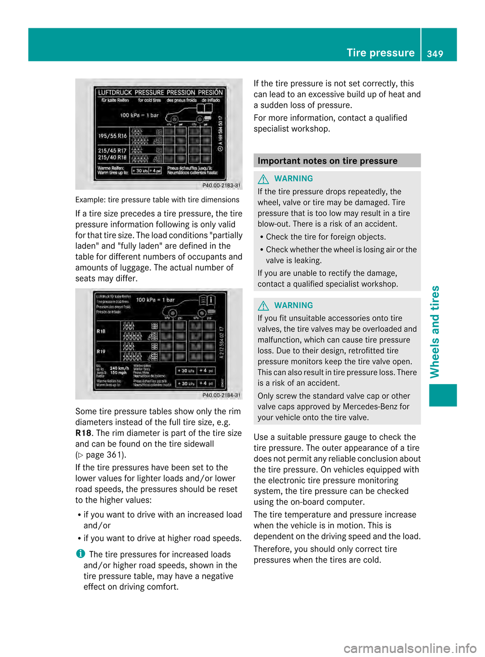
Example: tire pressure table with tire dimensions
If a tire size precedes a tire pressure, the tire
pressure informatio nfollowing is only valid
for that tire size. The load conditions "partially
laden" and "fully laden" are defined in the
table for different numbers of occupants and
amounts of luggage. The actual number of
seats may differ. Some tire pressure tables show only the rim
diameters instead of the full tire size, e.g.
R18. The rim diameter is part of the tire size
and can be found on the tire sidewall
(Y page 361).
If the tire pressures have been set to the
lower values for lighter loads and/or lower
road speeds, the pressures should be reset
to the higher values:
R if you want to drive with an increased load
and/or
R if you want to drive at higher road speeds.
i The tire pressures for increased loads
and/or higher road speeds, shown in the
tire pressure table, may have a negative
effect on driving comfort. If the tire pressure is not set correctly, this
can lead to an excessive build up of heat and
a sudden loss of pressure.
For more information, contact a qualified
specialist workshop. Important notes on tire pressure
G
WARNING
If the tire pressure drops repeatedly, the
wheel, valve or tire may be damaged. Tire
pressure that is too low may result in a tire
blow-out. There is a risk of an accident.
R Check the tire for foreign objects.
R Check whether the wheel is losing air or the
valve is leaking.
If you are unable to rectify the damage,
contact a qualified specialist workshop. G
WARNING
If you fit unsuitable accessories onto tire
valves, the tire valves may be overloaded and
malfunction, which can cause tire pressure
loss. Due to their design, retrofitted tire
pressure monitors keep the tire valve open.
This can also result in tire pressure loss. There
is a risk of an accident.
Only screw the standard valve cap or other
valve caps approved by Mercedes-Benz for
your vehicle onto the tire valve.
Use a suitable pressure gauge to check the
tire pressure. The outer appearance of a tire
does not permit any reliable conclusion about
the tire pressure. On vehicles equipped with
the electronic tire pressure monitoring
system, the tire pressure can be checked
using the on-board computer.
The tire temperature and pressure increase
when the vehicle is in motion .This is
dependent on the driving speed and the load.
Therefore, you should only correct tire
pressures when the tires are cold. Tire pressure
349Wheels and tires Z
Page 352 of 394
The tires are cold:
R
if the vehicle has been parked without
direct sunlight on the tires for at least three
hours and
R if the vehicle has been driven for less than
1 mile (1.6 km).
The tire temperature changes depending on
the outside temperature, the vehicle speed
and the tire load. If the tire temperature
changes by 18 ‡ (10 †), the tire pressure
changes by approximately 10 kPa (0.1 bar/
1.5 psi). Take this into account when
checking the pressure of warm tires. Only
correc tthe tire pressure if it is too low for the
current operating conditions. If you check the
tire pressure when the tires are warm, the
resulting value will be higher than if the tires
were cold. This is normal. Do not reduce the
tire pressure to the value specified for cold
tires. The tire pressure would otherwise be
too low.
Observe the recommended tire pressures for
cold tires:
R on the Tire and Loading Information placard
on the B-pillar on the driver's side
R in the tire pressure table on the inside of
the fuel filler flap
R on the yellow label on the emergency spare
wheel (depending on the vehicle
equipment) Underinflated or overinflated tires
Underinflation G
WARNING
Tires with pressure that is too low can
overheat and burst as a consequence. In
addition, they also suffer from excessive and/
or irregular wear, which can severely impair
the braking properties and the driving
characteristics. There is a risk of an accident.
Avoid tire pressures that are too low in all the
tires, including the spare wheel. Underinflated tires may:
R
overheat, leading to tire defects
R have an adverse effect on handling
characteristics
R wear quickly and unevenly
R have an adverse effect on fuel consumption
Overinflation G
WARNING
Tires with excessively high pressure can burst
because they are damaged more easily by
road debris, potholes etc. In addition, they
also suffer from irregular wear, which can
severely impair the braking properties and the
driving characteristics. There is a risk of an
accident.
Avoid tire pressures that are too high in all the
tires, including the spare wheel.
Overinflated tires may:
R increase the braking distance
R have an adverse effect on handling
characteristics
R wear quickly and unevenly
R have an adverse effect on ride comfort
R be more susceptible to damage
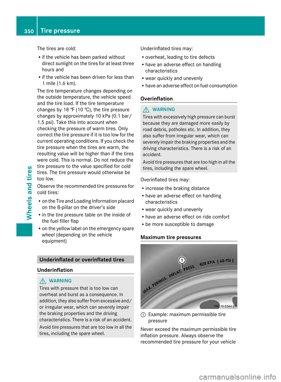
Maximum tire pressures 0002
Example: maximum permissible tire
pressure
Never exceed the maximum permissible tire
inflation pressure. Always observe the
recommended tire pressure for your vehicle 350
Tire pressureWheels and tires