MERCEDES-BENZ E-CLASS CABRIOLET 2017 Owners Manual
Manufacturer: MERCEDES-BENZ, Model Year: 2017, Model line: E-CLASS CABRIOLET, Model: MERCEDES-BENZ E-CLASS CABRIOLET 2017Pages: 521, PDF Size: 10.64 MB
Page 161 of 521
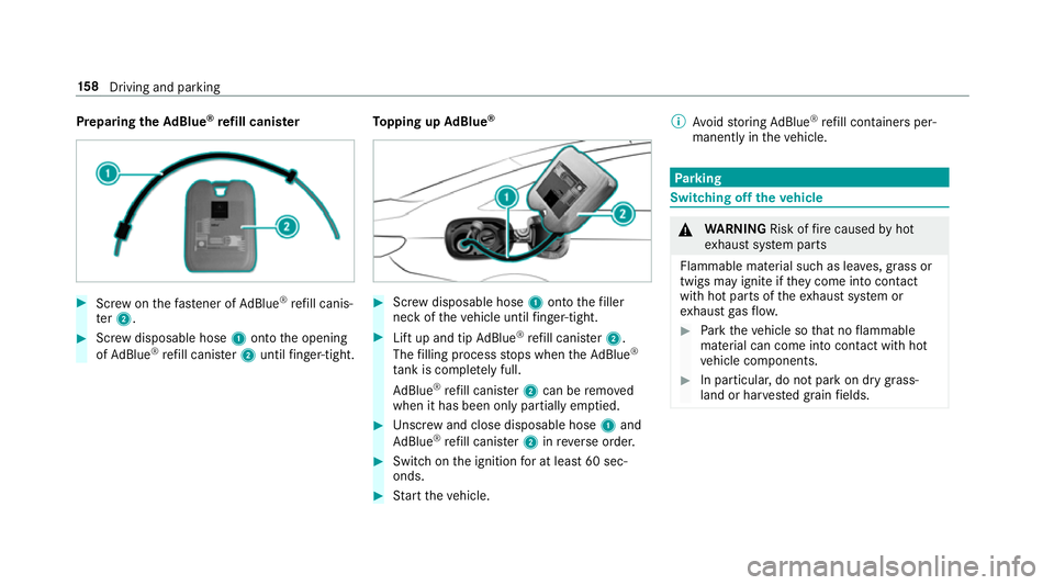
Preparing
theAd Blue ®
re fill canis ter #
Screw onthefast ener of AdBlue ®
re fill canis‐
te r2. #
Screw disposable hose 1onto the opening
of Ad Blue ®
re fill canis ter2 until finger-tight. To
pping up AdBlue ® #
Screw disposable hose 1onto thefiller
neck of theve hicle until finger-tight. #
Lift up and tip AdBlue ®
re fill canis ter2.
The filling process stops when theAd Blue ®
ta nk is compl etely full.
Ad Blue ®
re fill canis ter2 can be remo ved
when it has been only partially em ptied. #
Unscr ew and close disposable hose 1and
Ad Blue ®
re fill canis ter2 inreve rse order. #
Switch on the ignition for at least 60 sec‐
onds. #
Start theve hicle. %
Avoid storing AdBlue ®
re fill con tainers per‐
manently in theve hicle. Pa
rking Switching off
theve hicle &
WARNING Risk offire caused byhot
ex haust sy stem parts
Flammable material such as lea ves, grass or
twigs may ignite if they come into contact
wi th hot parts of theex haust sy stem or
ex haust gasflow. #
Park theve hicle so that no flammable
material can come into con tact wi thhot
ve hicle components. #
In particular, do not park on dry grass‐
land or har vested grain fields. 15 8
Driving and pa rking
Page 162 of 521
&
WARNING Risk of accident and inju ry
due tochildren left unat tended in the
ve hicle
If yo u lea vechildren unat tended in theve hi‐
cle, they may be able toset theve hicle in
motion, forex ample by:
R Releasing the parking brake.
R Shifting the transmission out of park
position j.
R Starting the engine.
In addition, they may operate vehicle equip‐
ment. #
Never lea vechildren and animals unat‐
te nded in theve hicle. #
When leaving theve hicle, alw aysta ke
th eke y with you and lock theve hicle.
This also applies tomobile phones if the
"Digital Car Key in the smartphone"
function is activated via the Mercedes
me connect web app. *
NO
TEDama getotheve hicle or the driv‐
et ra in caused bytheve hicle rolling away #
Alw ays proper lysecure theve hicle
against rolling away. #
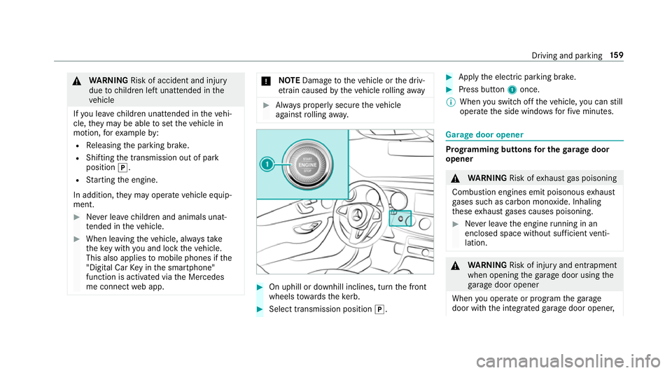
On uphill or downhill inclines, turn the front
wheels towa rdsth eke rb. #
Select transmission position j. #
Apply the electric parking brake. #
Press button 1once.
% When you swit choff theve hicle, you can still
opera tethe side windo wsforfive minutes. Garage door opener
Prog
ramming buttons for the garage door
opener &
WARNING Risk ofexhaust gas poisoning
Combustion engines emit poisonous exhaust
ga ses such as carbon monoxide. Inhaling
th ese exhaust gases causes poisoning. #
Never lea vethe engine running in an
enclosed space wi thout suf ficient venti‐
lation. &
WARNING Risk of inju ryand ent rapment
when opening thega rage door using the
ga rage door opener
When you operate or program thega rage
door with the integrated garage door opener, Driving and parking
15 9
Page 163 of 521
persons in
thera nge of mo vement of the
ga rage door can become trapped or stru ck
by thega rage door. #
When using the integrated garage door
opener, alw ays make sure that nobody
is within the sweep of thega rage door. Prior
toprog ramming a garage door opener, park
th eve hicle outside thega rage and swit choff the
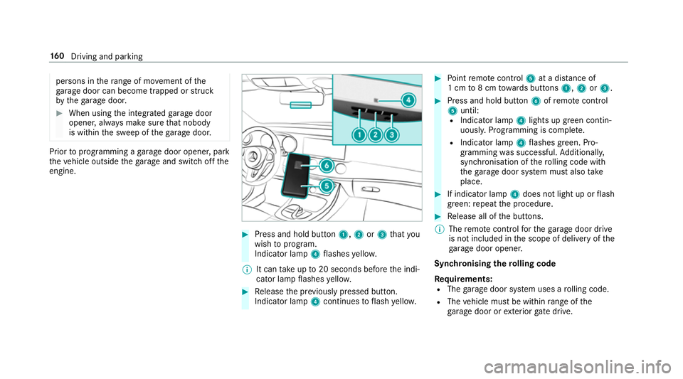
engine. #
Press and hold button 1,2or3 that you
wish toprog ram.
Indicator lamp 4flashes yello w.
% It can take up to20 seconds before the indi‐
cator lamp flashes yello w. #
Release the pr eviously pressed button.
Indicator lamp 4continues toflash yello w. #
Point remo tecontrol 5at a di stance of
1 cm to8 cm towa rds buttons 1,2or3. #
Press and hold button 6ofremo tecontrol
5 until:
R Indicator la mp4lights up green contin‐
uousl y.Programming is comple te.
R Indicator lamp 4flashes green. Pro‐
gr amming was successful. Additionally,
synchronisation of thero lling code with
th ega rage door sy stem must also take
place. #
If indicator lamp 4does not light up or flash
green: repeat the procedure. #
Release all of the buttons.
% The remo tecontrol forth ega rage door drive
is not included in the scope of delivery of the
ga rage door opener.
Synchronising thero lling code
Re quirements:
R The garage door sy stem uses a rolling code.
R The vehicle must be within range of the
ga rage door or exterior gate drive. 16 0
Driving and pa rking
Page 164 of 521
R
The vehicle as well as persons and objects,
are located outside the sweep of thega rage
door. #
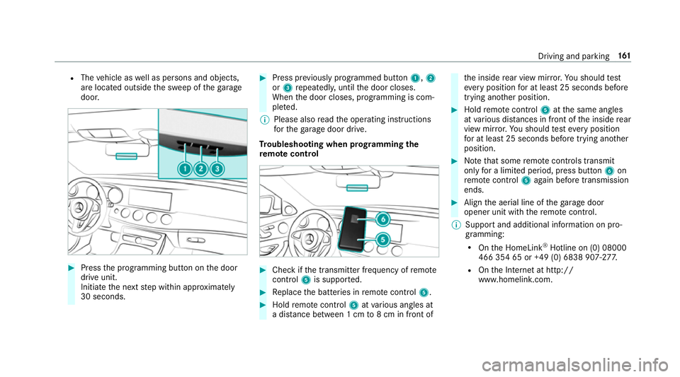
Press the programming button on the door
drive unit.
Initiate the next step within appr oximately
30 seconds. #
Press pr eviously prog rammed button 1,2
or 3 repeatedl y,until the door closes.
When the door closes, programming is com‐
ple ted.
% Please also read the operating instructions
fo rth ega rage door drive.
Tr oubleshooting when prog ramming the
re mo tecont rol #
Check if the transmit ter frequency of remo te
control 5is suppo rted. #
Replace the batteries in remo tecontrol 5. #
Hold remo tecontrol 5atvarious angles at
a dis tance between 1 cm to8 cm in front of th
e inside rear view mir ror.Yo u should test
eve ryposition for at least 25 seconds before
trying ano ther position. #
Hold remo tecontrol 5atthe same angles
at various dis tances in front of the inside rear
view mir ror.Yo u should test eve ryposition
fo r at least 25 seconds before trying ano ther
position. #
Notethat some remo tecontrols transmit
only for a limi ted period, press button 6on
re mo tecontrol 5again before transmission
ends. #
Align the aerial line of thega rage door
opener unit with there mo tecontrol.
% Support and additional information on pro‐
gramming:
R Onthe HomeLink ®
Hotline on (0) 08000
466 354 65 or +49 (0) 6838 907-2 77.
R Onthe Internet at http://
www.homelin k.com. Driving and pa
rking 161
Page 165 of 521
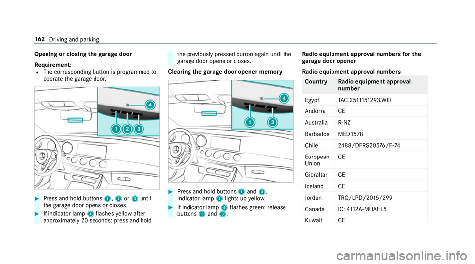
Opening or closing
thega rage door
Re quirement:
R The cor responding button is programmed to
operate thega rage door. #
Press and hold buttons 1,2or3 until
th ega rage door opens or closes. #
If indicator lamp 4flashes yellow af ter
appr oximately 20 seconds: press and hold th
e pr eviously pressed button again until the
ga rage door opens or closes.
Clearing thega rage door opener memo ry #
Press and hold buttons 1and 3.
Indicator lamp 4lights up yello w. #
If indicator lamp 4flashes green: release
buttons 1and 3. Ra
dio equipment appr oval numbers for the
ga rage door opener
Ra dio equipment appr oval numbers Countr
yRadio equipment appr oval
number
Egyp tT AC.25 111 51293.WIR
Andor ra CE
Au stra lia R-NZ
Barbados MED1 578
Chile 2488/DFRS205 76/F-74
European
Union CE
Gibral tarCE
Iceland CE
Jordan TRC/LPD/20 15/299
Canad aI C:4112 A-MUAHL5
Ku wa it CE 16 2
Driving and pa rking
Page 166 of 521
Count
ryRadio equipment appr oval
number
Liechten‐
st ein CE
Mexico RCPGEMU15-0448
Monaco CE
New Zea‐
land R-
NZ
Nor wayCE
Ru ssian
Fe dera‐
tion not
requ ired
Saudi Ara‐
bia TA
10525
Switzer‐
land CE Countr
yRadio equipment appr oval
number
South
Africa TA
-20 15/1386
Tu rkey notrequ ired
Uni ted
Arab Emi‐
ra tes ER4
1849/15
Dealer No: DA35176/14
United
St ates FCC ID: NZLM
UAHL5 Brazil
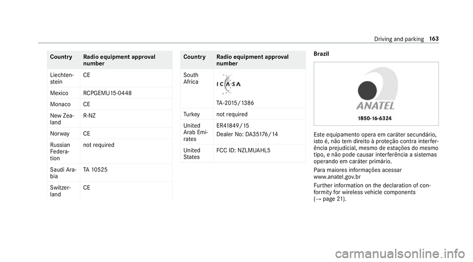
Es
te equipamento opera em caráter secundário,
is to é, não tem direito à pr oteção contra inter fer‐
ência prejudicial, mesmo de es tações do mesmo
tipo, e não pode causar inter ferê ncia a si stemas
operando em caráter primário.
Pa ra maio res informações acessar
www.anatel.go v.br
Fu rther information on the declaration of con‐
fo rm ity for wireless vehicle components
(→ page 21). Driving
and parking 16 3
Page 167 of 521
Electric pa
rking brake Au
tomatically applying the electric parking
brake &
WARNING Risk of accident and inju ry
due tochildren left unat tended in the
ve hicle
If yo u lea vechildren unat tended in theve hi‐
cle, they may be able toset theve hicle in
motion, forex ample by:
R Releasing the parking brake.
R Shifting the transmission out of park
position j.
R Starting the engine.
In addition, they may operate vehicle equip‐
ment. #
Never lea vechildren and animals unat‐
te nded in theve hicle. #
When leaving theve hicle, alw aysta ke
th eke y with you and lock theve hicle.
This also applies tomobile phones if the
"Digital Car Key in the smartphone" function is activated via
the Mercedes
me connect web app. The elect
ric pa rking brake is applied if the trans‐
mission is in position jand one of thefo llow‐
ing conditions is fulfilled:
R The engine is switched off.
R The seat belt tongue is not inser ted in the
seat belt buckle of the driver's seat and the
driver's door is opened.
% Toprev ent application: pull the handle of the
electric parking brake.
In thefo llowing situations, the electric parking
brake is also engaged:
R Distance Pilot DISTRONIC brings theve hicle
to ast andstill.
R The HOLD function is keeping theve hicle sta‐
tionar y.
R Parking Pilot is keeping theve hicle station‐
ar y. This is only
the case if one of thefo llowing con‐
ditions is also fulfilled:
R The engine is switched off.
R The seat belt tongue is not inser ted in the
seat belt buckle of the driver's seat and the
driver's door is opened.
R There is a sy stem malfunction.
R The po wer supply is insuf ficient.
R The vehicle is stationary for a lengt hyperiod.
When the electric parking brake is applied,
th e! indicator lamp lights up in the instru‐
ment clus ter.
The electric parking brake is not automatically
applied if the engine is switched off bythe ECO
st art/ stop function.
Re leasing the electric pa rking brake auto‐
matically
The elect ric pa rking brake is released when the
fo llowing conditions are fulfilled:
R The engine is running.
R The seat belt tongue is inser ted into the seat
belt buckle of the driver's seat. 16 4
Driving and pa rking
Page 168 of 521
R
The transmission is in position hork and
yo u depress the accelera tor pedal or you
shift from transmission position jtoh or
k.
R Ifth e transmission is in position k,the boot
lid must be closed.
If th e seat belt tongue is not inser ted into the
seat belt buckle of the driver's seat, thefo llow‐
ing conditions must be fulfilled:
R The driver's door is closed.
R You mo vethe transmission out of transmis‐
sion position joryou ha veprev iously
driven fasterthan 3 km/h.
R Ifth e transmission is in position k,the boot
lid must be closed.
If th e electric parking brake is released,
th e! indicator lamp in the instrument clus‐
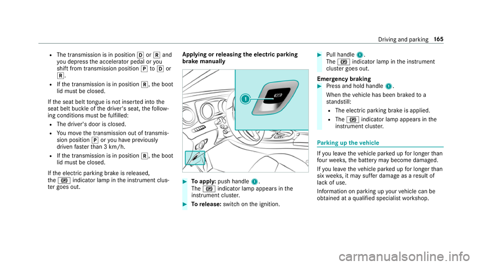
te r goes out. Applying or
releasing the electric pa rking
brake manually #
Toappl y:push handle 1.
The ! indicator lamp appears in the
instrument clus ter. #
Torelease: switch on the ignition. #
Pull handle 1.
The ! indicator lamp in the instrument
clus ter goes out.
Emer gency braking #
Press and hold handle 1.
When theve hicle has been braked to a
st andstill:
R The electric parking brake is applied.
R The ! indicator lamp appears in the
instrument clus ter. Pa
rking up theve hicle If
yo u lea vetheve hicle par ked up for longer than
fo ur we eks, the battery may become damaged.
If yo u lea vetheve hicle par ked up for longer than
six weeks, it may suf fer dama geas a result of
lack of use.
Information on parking up your vehicle can be
obtained at a qualified specialist workshop. Driving and parking
16 5
Page 169 of 521
St
andby mode (extension of the star ter bat‐
te ry 's period out of use) St
andby mode function
If standby mode is activated, theve hicle can be
par kedfo r an extended pe riod of time without
losing po wer.
St andby mode is characterised bythefo llowing:
R thest ar ter battery is preser ved.
R the maximum period out of use is displa yed
in the multimedia sy stem displa y.
R functions such as interior pr otection or tow-
aw ay protection are not available.
R the connection toonline services is inter rup‐
te d.
If th efo llowing conditions are fulfilled, standby
mode can be activated or deactivated using the
multimedia sy stem:
R the engine is switched off.
R the ignition is switched on.
Exceeding theve hicle's displa yed period out of
use may cause incon venience, i.e. it cannot be guaranteed
that thest ar ter battery will reliably
st art the engine.
The star ter battery must be charge dfirs t in the
fo llowing situations:
R theve hicle's period out of use must be
ex tended.
R theBattery charge insufficient for standby
mode message appears in the multimedia
sy stem displa y.
% Standby mode is automatically deactivated
when the ignition is switched on.
Ac tivating or deactivating standby mode
Multimedia sy stem:
, Vehicle .
î Vehicle set-
tings .
Standby mode #
Activate Oor deacti vate ª the function.
When you activate the function, a prom pt
appears. #
Select Yes.
St andby mode is activated. Driving and driving saf
ety sy stems Driving sy
stems and your responsibility Yo
ur vehicle is equipped with driving sy stems
which assist you in driving, parking and manoeu‐
vring theve hicle. The driving sy stems are aids
and do not relie ve you of your responsibility. Pay
attention tothe tra ffic conditions at all times
and inter vene when necessa ry. Be aware of the
limitations rega rding the safe use of these sys‐
te ms. Fu
nction of thera dar senso rs Some driving and driving sa
fety sy stems use
ra dar sensors tomonitor the area in front of,
behind or next totheve hicle (depending on the
ve hicle's equipment).
Depending on theve hicle's equipment, thera dar
sensors are integrated behind the bumpers
and/or behind thera diator grille. Keep these
parts free of dirt, ice and slush (→ page 358).
The sensors must not be co vered, forex ample
by bicycle rack s, ove rhanging loads or radar-
re flecting sticke rs.Fo llowing an impact and in 16 6
Driving and pa rking
Page 170 of 521
th
eeve nt of associated dama ge, which may not
be visible, tothe bumpers or radiator grille, ha ve
th e function of thera dar sensors checked at a
qu alified specialist workshop. The driver assis‐
ta nce sy stem may no longer workproperly. Overview of driving sy
stems and driving
saf ety sy stems In
this section, you will find information about
th efo llowing driving sy stems and driving saf ety
sy stems:
R 360° Camera (→ page 201)
R ABS (Anti-lock BrakingSystem) (→ page167)
R Distance Pilot DISTRONIC (→ page 180)
R Adaptive brake lights (→ page177)
R AIR BODY CONTROL (→ page191)
R Active Brake Assi st (→page 172)
R Active Lane Keeping Assist (→ page215)
R ATTENTION ASSIST (→ page 209)
R BAS (Bra keAssist System) (→ page168)
R DYNA MIC BODY CONTROL (→ page191) R
EBD ( Electronic Brakeforc eDistribution)
(→ page 171)
R ESP ®
(Electronic Stability Program)
(→ page 168)
R Hill Start Assist (→ page189)
R HOLD function (→ page190)
R STEER CONTROL (→ page 172)
R Steering Pilot (→ page187)
R Limi ter (→ page 177)
R Parking Pilot (→ page 204)
R Parking Assist PARKTRONIC(→ page194)
R Reversing camera (→ page198)
R Cruise control (→ page 177)
R Blind Spot Assi stand Active Blind Spot Assi st
( → page 213)
R Traf fic Sign Assi st (→page 210) Fu
nctions of ABS (anti-lock braking sy stem) ABS
regulates the brake pressure in critical driv‐
ing situations:
R During braking, e.g. at maximum full-s top
braking or insuf ficient traction of the tyres,
th e wheels are pr evented from blocking.
R Vehicle steerability while braking is ensured.
If ABS inter venes when braking, you will feel a
pulsing in the brake pedal. The pulsating brake
pedal can be an indication of hazardous road
conditions and can ser veas a reminder totake
ex tra care while driving.
Sy stem limitations
R ABS is active from speeds of appr ox.
8 km/h.
R ABS may be impai red or may not function if a
malfunction has occur red and theye l‐
low ! ABSwarning lamp lights up contin‐
uously in the instrument clus ter af terthe
engine is star ted. Driving and parking
167