MERCEDES-BENZ E-CLASS CABRIOLET 2020 Owners Manual
Manufacturer: MERCEDES-BENZ, Model Year: 2020, Model line: E-CLASS CABRIOLET, Model: MERCEDES-BENZ E-CLASS CABRIOLET 2020Pages: 469, PDF Size: 8.47 MB
Page 121 of 469
#
Alw aysstow and secure heavy, hard,
poin ted, sharp-edged, fragile or bulky
objects in the boot. Obser
vethe no tes on loading theve hicle. #
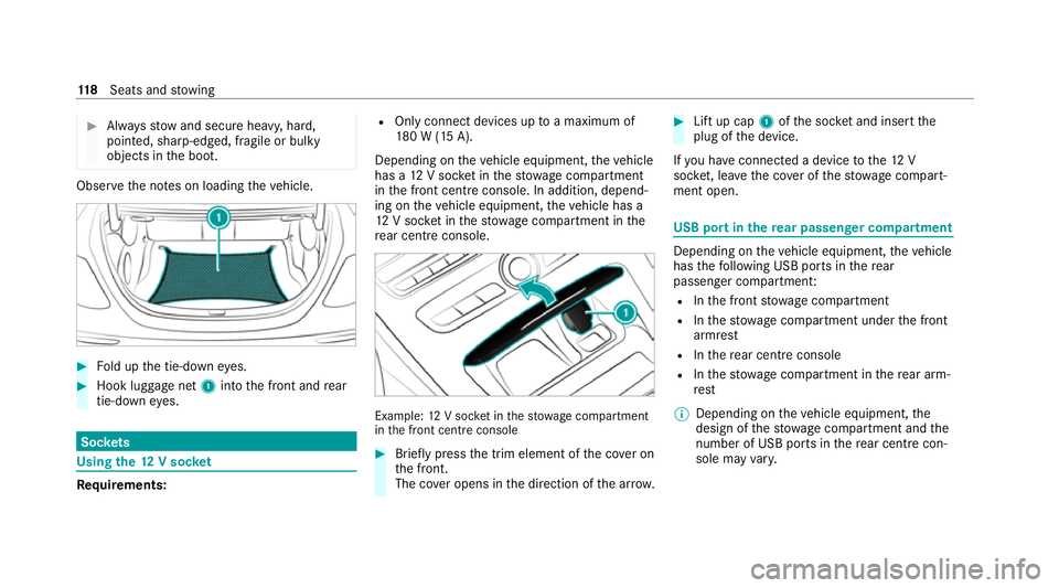
Fold up the tie-down eyes. #
Hook luggage net 1into the front and rear
tie-down eyes. Soc
kets Using the
12V so cket Re
quirements: R
Only connect devices up toa maximum of
18 0 W (15 A).
Depending on theve hicle equipment, theve hicle
has a 12V soc ket in thestow age compartment
in the front cent reconsole. In addition, depend‐
ing on theve hicle equipment, theve hicle has a
12 V soc ket in thestow age compartment in the
re ar centre console. Example:
12V soc ket in thestow age compartment
in the front cent reconsole #
Brief lypress the trim element of the co ver on
th e front.
The co ver opens in the direction of the ar row. #
Lift up cap 1ofthe soc ket and insert the
plug of the device.
If yo u ha veconnected a device tothe12 V
soc ket, le ave the co ver of thestow age compart‐
ment open. USB port in
there ar passen ger co mpartment Depending on
theve hicle equipment, theve hicle
has thefo llowing USB ports in there ar
passenger compartment:
R Inthe front stowage compartment
R Inthestow age compartment under the front
armrest
R Inthere ar centre console
R Inthestow age compartment in there ar arm‐
re st
% Depending on theve hicle equipment, the
design of thestow age compartment and the
number of USB po rts in there ar centre con‐
sole may vary. 11 8
Seats and stowing
Page 122 of 469
If
th e ignition is switched on you can charge a
USB device, e.g. a mobile phone, at the USB
ports using a suitable charging cable.
The devices can be charge d with 5 V (up to3 A)
and when the ignition is switched on. Wire
lesscharging of the mobile phone and
connection with theex terior aerial Note
s on wirelessly charging the mobile
phone &
WARNING Risk of inju rydue toobjects
being stowed incor rectly
If objects in theve hicle interior are stowed
incor rectly, they can slide or be thrown
around and hit vehicle occupants. In addi‐
tion, cup holders, open stowage spaces and
mobile phone recep tacles cannot al ways
re tain all objects within.
There is a risk of injur y,particularly in the
ev ent of sudden braking or a sudden change
in direction. #
Alw aysstow objects so that they can‐
not be throw n around in su chsitua‐
tions. #
Alw ays make sure that objects do not
pr otru de from stowage spaces, luggage
nets or stowage nets. #
Close the loc kable stow age spaces
before starting a journe y. #
Alw aysstow and secure heavy, hard,
poin ted, sharp-edged, fragile or bulky
objects in the boot/load compartment. Obser
vethe no tes on loading theve hicle. &
WARNING Risk offire from placing
objects in the mobile phone stowage
compartment
Placing other objects in the mobile phone
stow age compartment could con stitute a fire
hazard. #
Apart from a mobile phone, do not
place any other objects in the mobile phone
stowage compartment, espe‐
cially those made of me tal. *
NO
TEDama getoobjects caused by
placing them in the mobile phone stow‐
age compartment If objects are placed in
the mobile phone
stow age compartment, they may be dam‐
aged byelectromagnetic fields. #
Do not place credit cards, data storage
devices, ski passes or other objects
sensitive toelectromagnetic fields in
th e mobile phone stowage compart‐
ment. *
NO
TEDama getothe mobile phone
stow age compartment caused byliquids If liquids enter
the mobile phone stowage
compartment, the compartment may be
damaged. #
Ensure that no liquids enter the mobile
phone stowage compartment. Seats and
stowing 11 9
Page 123 of 469
R
Depending on theve hicle equipment, the
mobile phone is connected totheve hicle's
ex terior aerial via thech arging module.
R The charging function and wireless connec‐
tion of the mobile phone totheve hicle's
ex terior aerial are only available if the ignition
is switched on.
R Small mobile phones may not be able tobe
ch arge d in everyposition of the mobile
phone stowage compartment.
R Largemobile phones which do not rest flat in
th e mobile phone stowage compartment may
not be able tobe charge d or connec ted with
th eve hicle's exterior aerial.
R The mobile phone may heat up during the
ch arging process. The mobile phone can be
cooled in the mobile phone stowage com‐
partment when the air conditioning sy stem is
switched on. The cooling output in the
mobile phone stowage compartment is high‐
est when the controller in theglove box is
closed.
R Toensure more ef ficient charging and con‐
nection with theve hicle's exterior aerial, re
mo vethe pr otective co ver from the mobile
phone.
R When charging, the mat should be used if
possible. Wire
lessly charging a mobile phone Re
quirements:
R The mobile phone is suitable for wireless
ch arging (Qi-compatible mobile phone).
A list of Qi-compatible mobile phones can be
fo und at: https://www.mercedes-benz-
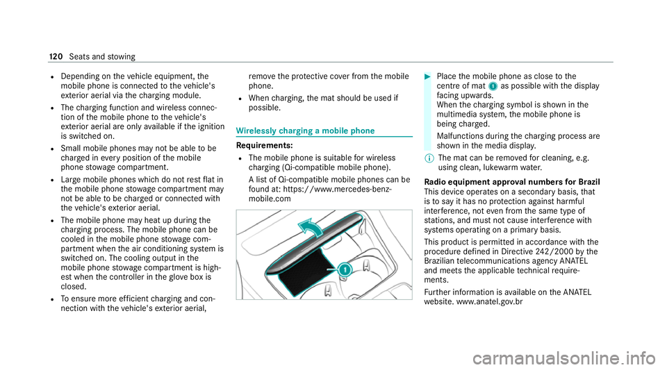
mobile.com #
Place the mobile phone as close tothe
centre of mat 1as possible wi th the display
fa cing up wards.
When thech arging symbol is shown in the
multimedia sy stem, the mobile phone is
being charge d.
Malfunctions during thech arging process are
shown in the media displa y.
% The mat can be remo vedfo r cleaning, e.g.
using clean, luk ewarmwate r.
Ra dio equipment appr oval numbers for Brazil
This device operates on a secondary basis, that
is to say it has no pr otection against harmful
inter fere nce, not even from the same type of
st ations, and must not cause inter fere nce wi th
sy stems operating on a primary basis.
This product is permitted in accordance with the
procedure defined in Directive 242/2000 bythe
Brazilian telecommunications agency AN ATEL
and meets the applicable tech nical requ ire‐
ments.
Fu rther information is available on the AN ATEL
we bsite. www.anatel.go v.br 12 0
Seats and stowing
Page 124 of 469
#
Further information on the declaration of
confo rmity forve hicle components which
re cei veand/or transmit radio wav es. Fi
tting and removing the floormats &
WARNING Risk of accident due to
objects in the driver's foot we ll
Objects in the driver's foot we ll may impede
pedal tr avel or block a depressed pedal.
This jeopardises the operating and road
saf ety of theve hicle. #
Stow all objects in theve hicle securely
so that they cannot getinto the driver's
fo ot we ll. #
Alw aysfit th efloor mats securely and
as prescribed in order toensure that
th ere is alw ays suf ficient room forthe
pedals. #
Do not use loose floor mats and do not
place floor mats on top of one ano ther. #
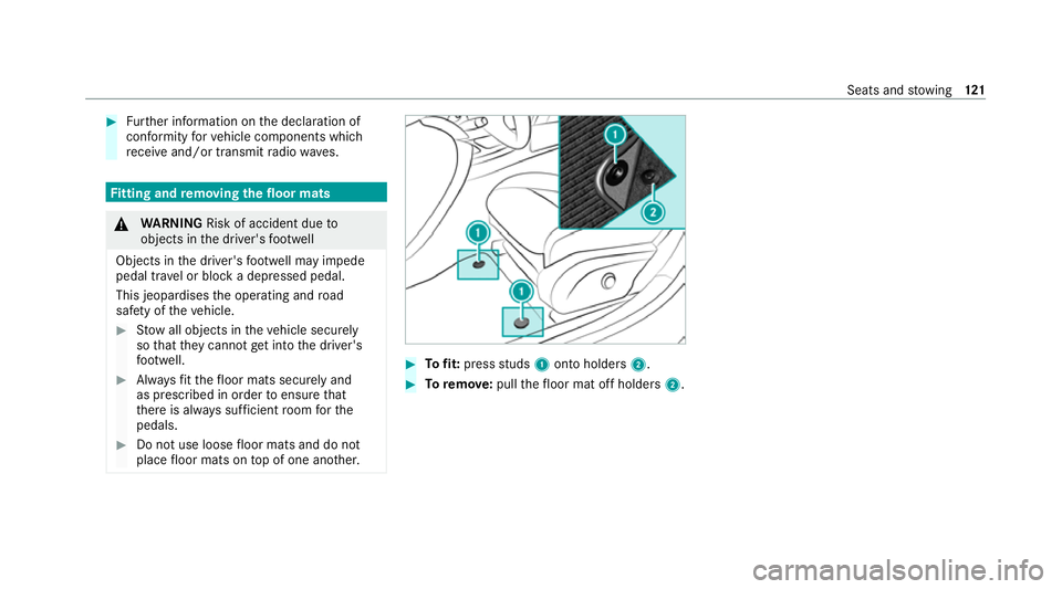
Tofit: press studs 1onto holders 2. #
Toremo ve:pull thefloor mat off holders 2. Seats and
stowing 121
Page 125 of 469
Exterior lighting
Note
s on adjusting the lights when driving
abroad Ve
hicles with static LED headlamps: it is not
necessa ryto con vert the headlamps. The legal
re qu irements are also met in countries in which
traf fic drives on theot her side of thero ad.
Ve hicles with Intelligent Light Sy stem: before
crossing the border into count ries in which traf‐
fi c drives on theot her side of thero ad, it is nec‐
essary toset the headlamps tosymmetrical low
beam (/ page130).
On ce the headlamps ha vebeen con verted:
R Oncoming tra ffic will not be dazzled.
R The edge of thero ad will not be illuminated
as far or as high.
R The "mo torw ay mode" and "enhanced fog
light" functions will not be available.
The headlamps must be reset toasymm etrical
low beam when youre turn from ab road. Information about lighting sy
stems and your
re sponsibility The
various lighting sy stems of theve hicle are
only aids. The driver of theve hicle is responsible
fo r cor rect vehicle illumination in accordance
with the pr evailing light and visibility conditions,
legal requirements and traf fic situation. Light switch
Ope
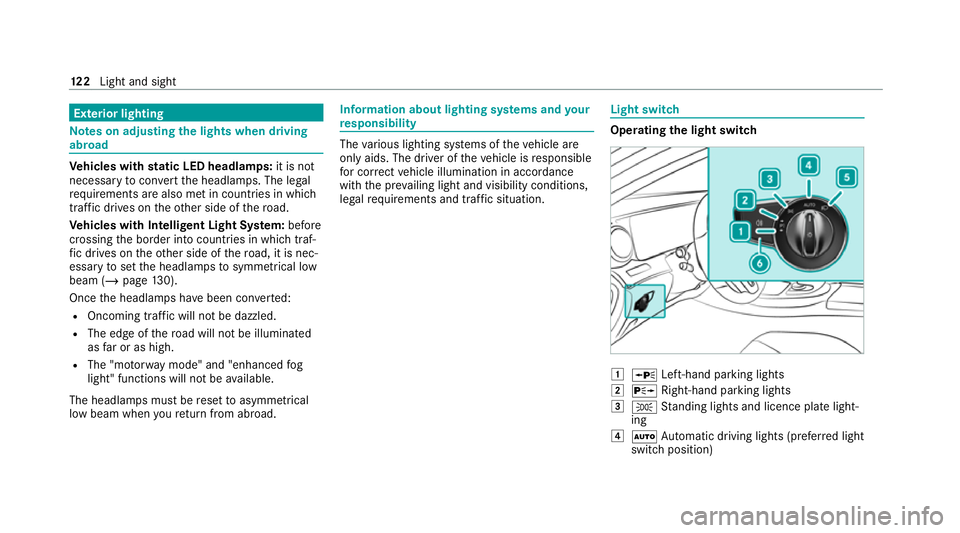
rating the light switch 1
W Left-hand pa rking lights
2 X Right-hand parking lights
3 T Standing lights and licence plate light‐
ing
4 Ã Automatic driving lights (prefer red light
switch position) 12 2
Light and sight
Page 126 of 469
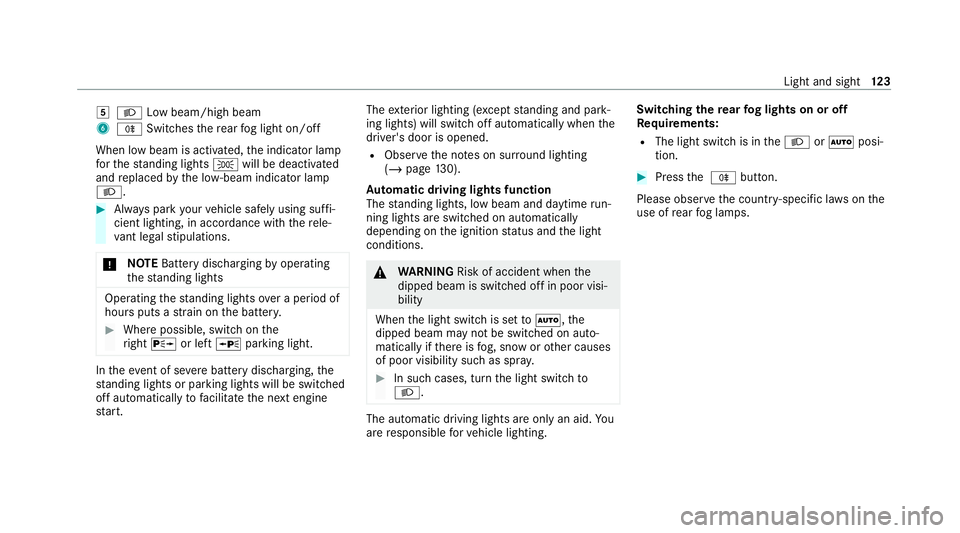
5
L Low beam/high beam
6 R Switches there ar fog light on/off
When low beam is activated, the indicator lamp
fo rth est anding lights Twill be deactivated
and replaced bythe lo w-beam indicator lamp
L. #
Alw ays park your vehicle safely using suf fi‐
cient lighting, in acco rdance with there le‐
va nt le galst ipulations.
* NO
TEBattery discharging byoperating
th est anding lights Operating
thest anding lights over a period of
hours puts a stra in on the batter y. #
Where possible, switch on the
ri ght X or left Wparking light. In
theeve nt of se vere battery discharging, the
st anding lights or parking lights will be swit ched
off automatically tofacilitate the next engine
st art. The
exterior lighting (e xcept standing and park‐
ing lights) will swit choff automatically when the
driver's door is opened.
R Obser vethe no tes on sur round lighting
(/ page 130).
Au tomatic driving lights function
The standing lights, low beam and daytime run‐
ning lights are switched on au tomatically
depending on the ignition status and the light
conditions. &
WARNING Risk of accident when the
dipped beam is switched off in poor visi‐
bility
When the light switch is set toà ,the
dipped beam may not be switched on auto‐
matically if there is fog, snow or other causes
of poor visibility such as spr ay. #
In such cases, turn the light switch to
L . The automatic driving lights are only an aid.
Yo u
are responsible forve hicle lighting. Switching
there ar fog lights on or off
Re quirements:
R The light switch is in theL orà posi‐
tion. #
Press the R button.
Please obser vethe count ry-specific la wsonthe
use of rear fog lamps. Light and sight
12 3
Page 127 of 469
Operating
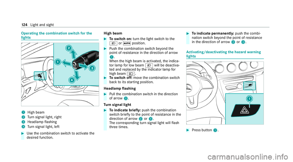
the combination switch for the
lights 1
High beam
2 Turn signal light, right
3 Headlamp flashing
4 Turn signal light, left #
Use the combination switch toactivate the
desired function. High beam #
Toswitch on: turnthe light switch tothe
L orà position. #
Push the combination switch be yond the
point of resis tance in the direction of ar row
1 .
When the high beam is activated, the indica‐
to r lamp for low beam Lwill be deactiva‐
te d and replaced bythe indicator lamp for
high beam K. #
Toswitch off: movethe combination switch
back toits starting position.
Headla mpflashing #
Pull the combination switch in the direction
of ar row3.
Tu rn signal light #
Toindicate briefl y:push the combination
switch briefly tothe point of resis tance in the
direction of ar row2or4.
The cor responding turn signal light will flash
th re e times. #
Toindicate permanentl y:push the combi‐
nation switch be yond the point of resis tance
in the direction of ar row2or4. Ac
tivating/deactivating the hazard warning
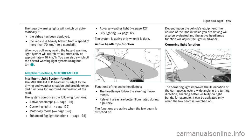
lights #
Press button 1. 124
Light and sight
Page 128 of 469
The hazard
warning lights will switch on auto‐
matically if:
R the airbag has been deplo yed.
R theve hicle is heavily braked from a speed of
more than 70 km/h toast andstill.
When you pull away again, the hazard warning
light sy stem will switch off automatically at
appr oximately 10km/h. You can also swit choff
th e hazard warning light sy stem using but‐
to n1. Ad
aptive functions, MULTIBEAM LED Intelligent Light Sy
stem function
The MULTIBEAM LED headlamps adapt tothe
driving and weather situation and pr ovide exten‐
ded functions for impr oved illumination of the
ro ad.
The sy stem comprises thefo llowing functions:
R Active headla mps (/ page125)
R Cornering light (/ page125)
R Motorw ay mode (/ page126)
R Enhanced fog light function (/ page126) R
Adversewe ather light (/ page127)
R City lighting (/ page127)
The sy stem is active only when it is dar k.
Ac tive headlamps function Fu
nctions of the active headlamps:
R The headlamps follow thesteering mo ve‐
ments.
R Releva nt areas are better illumina ted during
a journe y.
The functions are active when the low beam is
switched on. Depending on
theve hicle's equipment, the
cou rse of the lane in which you are driving will
also be evaluated and the active headlamps
function will adjust the light in advance.
Cornering light function The cornering light impr
ovesth e illumination of
th e car riag ewa yove r a wide angle in the turning
direction, enabling better visibility on tight
bends, forex ample. It can be activated on ly
when the low beam is switched on. Light and sight
12 5
Page 129 of 469
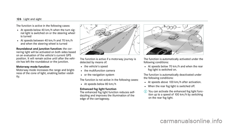
The function is active in
thefo llowing cases:
R Atspeeds below 40 km/h when the turn sig‐
nal light is switched on or thesteering wheel
is turned
R Atspeeds between 40 km/h and 70 km/h
and when thesteering wheel is turned
Ro undabout and junction function: the cor‐
nering light will be activated on bo thsides based
on an evaluation of theve hicle's cur rent GPS
position. It will remain active until af terth eve hi‐
cle has left thero undabout or the junction.
Mo torw ay mode function
Mo torw ay mode increases thera nge and bright‐
ness of the cone of light, enabling better visibil‐
ity. The function is active if a mo
torw ay jou rney is
de tected bymeans of:
R theve hicle's speed
R the multifunction camera
R orthe navigation sy stem
The function is not active in thefo llowing cases:
R Atspeeds below 80 km/h
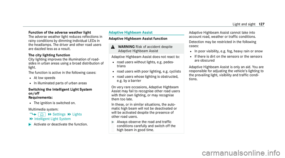
Enhanced fog light function
The enhanced fog light function reduces self-
dazzling and impr ovesth e illumination of the
edge of the car riag ewa y. The function is automatically activated under
the
fo llowing conditions:
R Atspeeds below 70 km/h and when there ar
fo g light is switched on.
The function is automatically deactivated under
th efo llowing conditions:
R Atspeeds abo ve100 km/h af ter activation.
R When there ar fog light is switched off.
% You can activate the enhanced fog light func‐
tion up toa speed of 100 km/h byswitching
on there ar fog light. 12 6
Light and sight
Page 130 of 469
Fu
nction of the ad versewe ather light
The adverse weather light reduces reflections in
ra iny conditions bydimming individual LEDs in
th e headlamps. The driver and other road users
are dazzled less as a result.
The city lighting function
City lighting impr oves the illumination of road‐
sides in urban areas using a broad distribution of
light.
The function is active in thefo llowing cases:
R Atlow speeds
R In illuminated parts of urban areas
Switching the Intelligent Light Sy stem
on/off
Re quirements:
R The ignition is switched on.
Multimedia sy stem:
4 © 5
Settings 5
Lights
5 Intelligent Light System #
Activate or deacti vate the function. Ad
aptive Highbeam Assist Ad
aptive Highbeam Assist function &
WARNING Risk of accident despi te
Ad aptive Highbeam Assist
Ad aptive Highbeam Assist does not react to:
R road users without lights, e.g. pedes‐
trians
R road users with poor lighting, e.g. cyclists
R road users whose lighting is obstructed,
e.g. bya bar rier
On very rare occasions, Adaptive Highbeam
Assist may failto recognise other road users
with their own lighting, or may recognise
th em too late.
In these, or in similar situations, the auto‐
matic high beam will not be deactivated or
will be activated despite the presence of
ot her road users. #
Alw ays obser vethero ad and traf fic
conditions carefully and switch off the
high beam in good time. Ad
aptive Highbeam Assist cannot take into
account road, weather or traf fic conditions.
De tection may be restricted in thefo llowing
cases:
R In poor visibilit y,e.g. fog, heavy rain or snow
R Ifth ere is dirt on the sensors or the sensors
are obscured
Ad aptive Highbeam Assist is on lyan aid. You are
re sponsible for adju sting theve hicle's lighting to
th e pr evailing light, visibility and traf fic condi‐
tions. Light and sight
127