MERCEDES-BENZ E-CLASS CABRIOLET 2020 Owners Manual
Manufacturer: MERCEDES-BENZ, Model Year: 2020, Model line: E-CLASS CABRIOLET, Model: MERCEDES-BENZ E-CLASS CABRIOLET 2020Pages: 469, PDF Size: 8.47 MB
Page 131 of 469
Ad
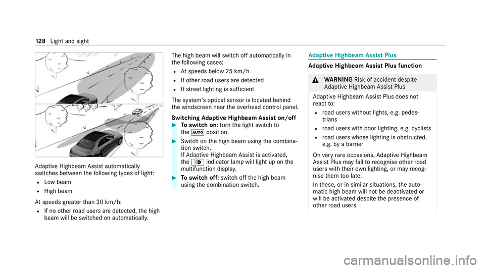
aptive Highbeam Assist automatically
swit ches between thefo llowing types of light:
R Low beam
R High beam
At speeds greater than 30 km/h:
R If no other road users are de tected, the high
beam will be switched on automaticall y.The high beam will switch off automatically in
th
efo llowing cases:
R Atspeeds below 25 km/h
R Ifot her road users are de tected
R Ifstre et lighting is suf ficient
The sy stem's optical sensor is located behind
th e windscreen near theove rhead control panel.
Switching Adaptive Highbeam Assist on/off #
Toswitch on: turnthe light switch to
th eà position. #
Switch on the high beam using the combina‐
tion switch.
If Ad aptive Highbeam Assist is activated,
th e_ indicator lamp will light up on the
multifunction displa y. #
Toswitch off: switch offthe high beam
using the combination switch. Ad
aptive Highbeam Assist Plus Ad
aptive Highbeam Assist Plus function &
WARNING Risk of accident despi te
Ad aptive Highbeam Assist Plus
Ad aptive Highbeam Assist Plus does not
re act to:
R road users without lights, e.g. pedes‐
trians
R road users with poor lighting, e.g. cyclists
R road users whose lighting is obstructed,
e.g. bya bar rier
On very rare occasions, Adaptive Highbeam
Assist Plus may failto recognise other road
users with their own lighting, or may recog‐
nise them too late.
In these, or in similar situations, the auto‐
matic high beam will not be deactivated or
will be activated despite the presence of
ot her road users. 12 8
Light and sight
Page 132 of 469

#
Alw ays obser vethero ad and traf fic
conditions carefully and switch off the
high beam in good time. Ad
aptive Highbeam Assist Plus cannot take into
account road, weather or traf fic conditions.
De tection may be restricted in thefo llowing
cases:
R In poor visibilit y,e.g. fog, heavy rain or snow
R Ifth ere is dirt on the sensors or the sensors
are obscured
Ad aptive Highbeam Assist Plus is on lyan aid.
Yo u are responsible for adju sting theve hicle's
lighting tothe pr evailing light, visibility and traf‐
fi c conditions. Ad
aptive Highbeam Assist Plus automatically
swit ches between thefo llowing types of light:
R Low beam
R Partial high beam
R High beam
R ULTRA RANGE Highbeam ULTRA RANGE Highbeam inc
reases the bright‐
ness of the cone of light tothe legally permitted
maximum.
Pa rtial high beam does not include other road
users in the high beam area. It does not dazzle
th em but enables full high beam illumination for
th e driver apart from theexc luded vehicles.
At speeds below 25 km/h or when there is suf fi‐
cient stre et lighting:
R The partial high beam and the high beam will
be switched off automaticall y.
At speeds greater than 30 km/h:
R If no other road users are de tected, the high
beam will be switched on automatically.
R Ifot her road users are de tected, the partial
high beam will be switched on automaticall y.
At speeds abo ve40 km/h:
R If no other road users are de tected on a
st ra ight road, ULTRA RANGE Highbeam will
be swit ched on automatically.
R Ifot her road users are de tected, the partial
high beam will be switched on automaticall y. Light and sight
12 9
Page 133 of 469
R
If highly reflective signs are de tected, ULTRA
RANGE Highbeam will be switched off au to‐
matical ly.
The sy stem's optical sensor is located behind
th e windscreen near theove rhead control panel.
Switching Adaptive Highbeam Assist Plus
on/off #
Toswitch on: turnthe light switch to
th eà position. #
Switch on the high beam using the combina‐
tion switch.
When the high beam is switched on automat‐
ically in the dar k,the_ indicator lamp on
th e multifunction display will light up. #
Toswitch off: switch offthe high beam
using the combination switch. Setting
the low beam (vehicles with MULTI‐
BEAM LED headlamps only) Multimedia sy
stem:
4 © 5
Settings 5
Lights
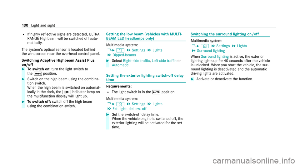
5 Dipped-beams #
Select Right-side traffic, Left-side trafficor
Automatic. Setting
theex terior lighting switch-off delay
time Re
quirements:
R The light switch is in theà position.
Multimedia sy stem:
4 © 5
Settings 5
Lights
5 Ext. light. del. sw. off #
Set the switch-off delay time.
When theve hicle engine is switched off, the
ex terior lighting will be activated forth e set
time. Switching
the sur round lighting on/off Multimedia sy
stem:
4 © 5
Settings 5
Lights
5 Surround lighting
When Surround lighting is active,theex terior
lighting lights up for 40 seconds af terth eve hicle
is unloc ked. When youstart theve hicle, the sur‐
ro und lighting is deactivated and the automatic
driving lights are activated. #
Activate or deacti vate the function. 13 0
Light and sight
Page 134 of 469
Interior lighting
Ad
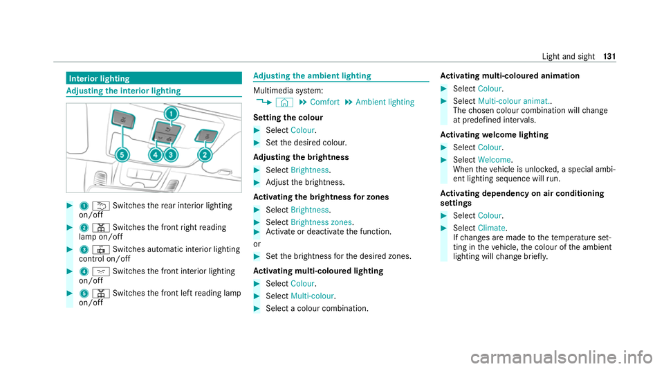
justing the in terior lighting #
1 u Switches there ar interior lighting
on/off #
2 p Switches the front right reading
lamp on/off #
3 | Switches automatic interior lighting
control on/off #
4 c Switches the front interior lighting
on/off #
5 p Switches the front left reading lamp
on/off Ad
justing the ambient lighting Multimedia sy
stem:
4 © 5
Comfort 5
Ambient lighting
Setting the colour #
Select Colour. #
Set the desired colour.
Ad justing the brightness #
Select Brightness . #
Adjust the brightness.
Ac tivating the brightness for zones #
Select Brightness . #
Select Brightness zones . #
Activate or deacti vate the function.
or #
Set the brightness forth e desired zones.
Ac tivating multi-coloured lighting #
Select Colour. #
Select Multi-colour. #
Select a colour combination. Ac
tivating multi-coloured animation #
Select Colour. #
Select Multi-colour animat..
The chosen colour combination will change
at predefined inter vals.
Ac tivating welcome lighting #
Select Colour. #
Select Welcome.
When theve hicle is unloc ked, a special ambi‐
ent lighting sequence will run.
Ac tivating dependency on air conditioning
settings #
Select Colour. #
Select Climate.
If ch anges are made tothete mp erature set‐
ting in theve hicle, the colour of the ambient
lighting will change brief ly. Light and sight
131
Page 135 of 469
Switching
the interior lighting switch-off
delay time on/off Multimedia sy
stem:
4 © 5
Settings 5
Lights
5 Int. light. del. sw. off #
Switch the switch-off delay time on or off.
When this function is active, the interior light‐
ing lights up for a short time af terth eve hicle
is loc ked. Wi
ndscreen wipers and windscreen washer
sy stem Switching
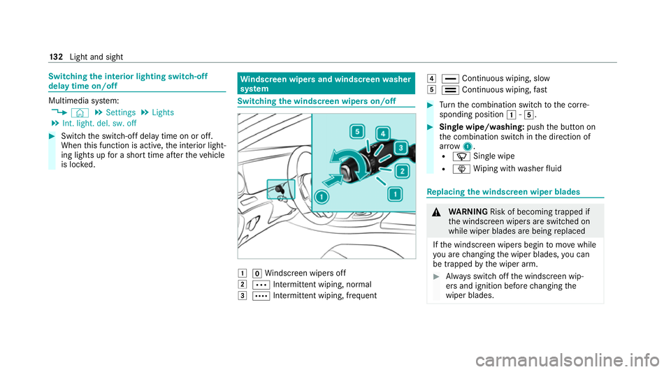
the windscreen wipers on/off 1
gWindsc reen wipers off
2 Ä Intermittent wiping, normal
3 Å Intermittent wiping, frequent 4
° Continuous wiping, slow
5 ¯ Continuous wiping, fast #
Turn the combination switch tothe cor re‐
sponding position 1-5. #
Single wipe/washing: pushthe button on
th e combination switch in the direction of
ar row 1.
R í Single wipe
R î Wiping with washer fluid Re
placing the windsc reen wiper blades &
WARNING Risk of becoming trapped if
th e windscreen wipers are switched on
while wiper blades are being replaced
If th e windscreen wipers begin tomo vewhile
yo u are changing the wiper blades, you can
be trapped bythe wiper arm. #
Alw ays switch off the windscreen wip‐
ers and ignition before changing the
wiper blades. 13 2
Light and sight
Page 136 of 469
Moving
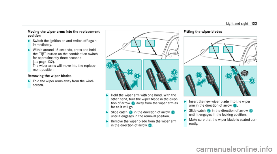
the wiper arms into there placement
position #
Switch the ignition on and switch off again
immediatel y. #
Within around 15seconds, press and hold
th eî button on the combination switch
fo r appro ximately thre e seconds
(/ page 132).
The wiper arms will mo veinto there place‐
ment position.
Re moving the wiper blades #
Foldthe wiper arms away from the wind‐
screen. #
Hold the wiper arm with one hand. With the
ot her hand, turn the wiper blade in the direc‐
tion of ar row1away from the wiper arm as
fa r as it will go. #
Slide catch 2inthe direction of ar row 3
until it engages in there mo val position. #
Remo vethe wiper blade from the wiper arm
in the direction of ar row4. Fi
tting the wiper blades #
Inse rtthe new wiper blade into the wiper
arm in the direction of ar row1. #
Slide catch 2inthe direction of ar row 3
until it engages in the locking position. #
Make sure that the wiper blade is seated cor‐
re ctly. Light and sight
13 3
Page 137 of 469
#
Foldthe wiper arms back onto the wind‐
screen. #
Switch on the ignition. #
Press theî button on the combination
switch.
The wiper arms will mo veinto the original
position. #
Switch the ignition off.
Maintenance display
The maintenance display is available on lywith
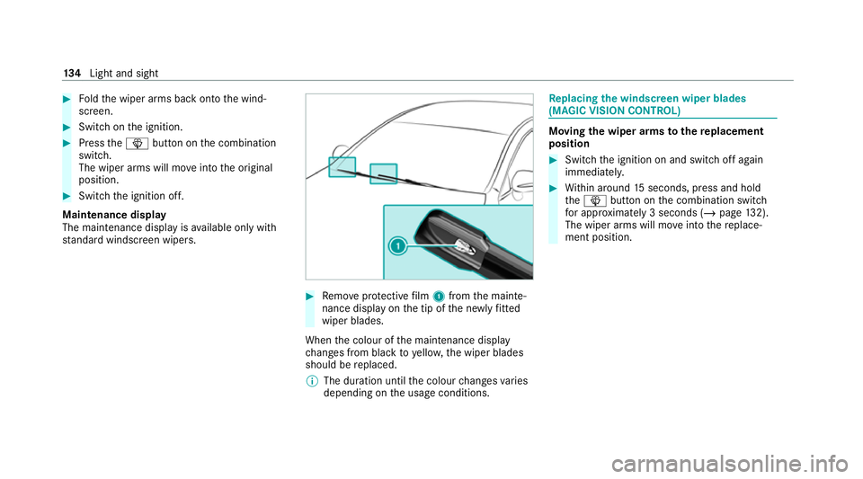
st andard windsc reen wipers. #
Remo veprotective film 1 from the mainte‐
nance display on the tip of the newly fitted
wiper blades.
When the colour of the maintenance display
ch anges from black to yellow, the wiper blades
should be replaced.
% The duration until the colour changes varies
depending on the usage conditions. Re
placing the windsc reen wiper blades
(MAGIC VISION CONT ROL) Moving
the wiper arms tothere placement
position #
Switch the ignition on and switch off again
immediatel y. #
Within around 15seconds, press and hold
th eî button on the combination switch
fo r appro ximately 3 seconds (/ page132).
The wiper arms will mo veinto there place‐
ment position. 134
Light and sight
Page 138 of 469
Re
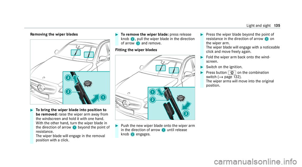
moving the wiper blades #
Tobring the wiper blade into position to
be remo ved: raise the wiper arm away from
th e windscreen and hold it with one hand.
Wi th th eot her hand, turn the wiper blade in
th e direction of ar row1beyond the point of
re sis tance.
The wiper blade will engage in there mo val
position with a clic k. #
Toremo vethe wiper blade: pressrelease
knob 2, pull the wiper blade in the direction
of ar row3and remo ve.
Fi tting the wiper blades #
Push the new wiper blade onto the wiper arm
in the direction of ar row1until release
knob 2engages. #
Press the wiper blade be yond the point of
re sis tance in the direction of ar row3on
th e wiper arm.
The wiper blade will engage with a noticeable
click and mo vefreely again. #
Foldthe wiper arm back onto the wind‐
screen. #
Switch on the ignition. #
Press button îonthe combination
switch (/ page132).
The wiper arms will mo veinto the original
position. Light and sight
13 5
Page 139 of 469
Mir
rors Operates
the outside mir rors &
WARNING Risk of accident due to
adjusting vehicle settings while theve hi‐
cle is in motion
Yo u could lose cont rol of theve hicle in the
fo llowing situations in particular:
R Ifyo u adjust the driver's seat, the head
re stra ints, thesteering wheel or the mir‐
ro r while theve hicle is in motion.
R Ifyo ufast enyour seat belt while theve hi‐
cle is in motion. #
Before starting the engine: adjust the
driver's seat, the head restra ints, the
st eering wheel and the mir ror and fas‐
te nyo ur seat belt. &
WARNING Risk of accident due tomis‐
judgement of dis tance when using the
outside mir ror
The outside mir rors reflect objects on a
smaller scale. The objects in view are in fact
closer than they appear. #
Therefore, alw ays look over your shoul‐
der in order toensure that you are
aw are of the actual dis tance between
yo u and thero ad users driving behind
yo u. Fo
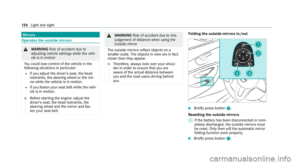
lding the outside mir rors in/out #
Brief lypress button 1.
Re setting the outside mir rors
% Ifth e battery has been disconnected or com‐
ple tely discharged, the outside mir rors must
be reset. Only then will the automatic mir ror
fo lding function workproperly. #
Brief lypress button 1. 13 6
Light and sight
Page 140 of 469
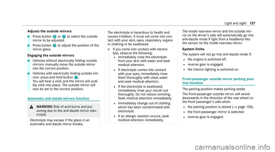
Ad
justs the outside mir rors #
Press button 3or4 toselect the outside
mir rorto be adjus ted. #
Press button 2toadjust the position of the
mir rorgl ass.
Engaging the outside mir rors #
Vehicles without electrically folding outside
mir rors: manually mo vethe outside mir ror
into the cor rect position. #
Vehicles with electrically folding outside mir‐
ro rs: press and hold button 1.
Yo u will hear a click and the mir ror will audi‐
bly click into place. The outside mir ror will
now be set tothe cor rect position. Au
tomatic anti-dazzle mir rors function &
WARNING Risk of acid bu rns and poi‐
soning due tothe anti-dazzle mir ror elec‐
trolyte
Electrolyte may escape if theglass in an
automatic anti-dazzle mir ror breaks. The electrolyte is hazardous
tohealth and
causes ir rita tion. It mu stnot come into con‐
ta ct wi thyour skin, eyes,respiratory or gans
or clo thing or be swallo wed. #
Ifyo u come into contact with electro‐
ly te , obser vethefo llowing:
R Immediately rinse the electrolyte
from your skin with water and seek
medical attention.
R If electrolyte comes into contact
with your eyes, immediately rinse
th em thoroughly with clean water
and seek medical attention.
R Ifth e electrolyte is swallo wed,
immediately rinse your mouth out
th oroughl y.Do not induce vomiting.
Seek medical attention immediately.
R Immedia tely ch ange out of clo thing
which has been con taminated with
electrolyte.
R If an allergic reaction occurs, seek
medical attention immediatel y. The inside
rearview mir ror and the outside mir‐
ro r on the driver's side will automatically go into
anti-dazzle mode if light from a headlamp hits
th e sensor on the inside rearview mir ror.
Sy stem limits
The sy stem will not go into anti-dazzle mode if:
R the engine is switched off.
R reve rsege ar is engaged.
R the interior lighting is switched on. Fr
ont-passenger outside mir ror parking posi‐
tion function The pa
rking position makes parking easier.
The front-passenger outside mir ror will swivel
down wards in the direction of there ar wheel on
th e front passenger's side when:
R the parking position is stored (/ page138).
R the front-passen ger mir ror is selected.
R reve rsege ar is engaged. Light and sight
137