seats MERCEDES-BENZ E-Class COUPE 2013 C207 Owner's Guide
[x] Cancel search | Manufacturer: MERCEDES-BENZ, Model Year: 2013, Model line: E-Class COUPE, Model: MERCEDES-BENZ E-Class COUPE 2013 C207Pages: 372, PDF Size: 12.69 MB
Page 118 of 372
i
If you are driving faster than 9 mph
(15 km/h
) you can no longer fold in the
exterior mirrors.
Setting the exterior mirrors This function is only available in vehicles for
Canada.
If the battery has been disconnected or
completely discharged, the exterior mirrors
must be reset. The exterior mirrors will
otherwise
not fold in when you select the Fold
in mirrors when locking function in the on-
board computer ( Y page 227).
X Make sure that the SmartKey is in
position 1 in the ignition lock.
X Briefly press button :.
Folding the exterior mirrors in or out
automatically This function is only available in vehicles for
Canada.
If
the "Fold in mirrors when locking" function
is activated in the on-board computer
(Y page 227):
R the exterior mirrors fold in automatically as
soon as you lock the vehicle from the
outside.
R the exterior mirrors fold out again
automatically as soon as you unlock the
vehicle and then open the driver's or front-
passenger door.
i If the exterior mirrors have been folded in
manually, they do not fold out.
Exterior mirror out of position If an exterior mirror has been pushed out of
position, proceed as follows:
X
Vehicles without electrically folding
exterior
mirrors: move the exterior mirror
into the correct position manually.
X Vehicles with electrically folding
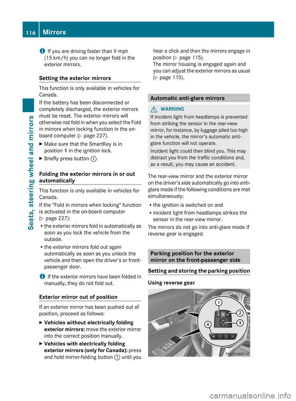
exterior
mirrors (only for Canada): press
and hold mirror-folding button : until youhear a click and then the mirrors engage in
position (Y page 115).
The mirror housing is engaged again and
you
can adjust the exterior mirrors as usual
(Y page 115). Automatic anti-glare mirrors
G
WARNING
If incident light from headlamps is prevented
from striking the sensor in the rear-view
mirror,
for instance, by luggage piled too high
in the vehicle, the mirror's automatic anti-
glare function will not operate.
Incident light could then blind you. This may
distract you from the traffic conditions and,
as a result, you may cause an accident.
The rear-view mirror and the exterior mirror
on the driver's side automatically go into anti-
glare mode if the following conditions are met
simultaneously:
R the ignition is switched on and
R incident light from headlamps strikes the
sensor in the rear-view mirror.
The mirrors do not go into anti-glare mode if
reverse gear is engaged. Parking position for the exterior
mirror on the front-passenger side
Setting
and storing the parking position Using reverse gear116
Mirrors
Seats, steering wheel and mirrors
Page 119 of 372
You can position the front-passenger side
exterior
mirror in such a way that you can see
the rear wheel on that side as soon as you
engage reverse gear. You can store this
position.
X Make sure that the vehicle is stationary and
that the SmartKey is in position 2 in the
ignition lock.
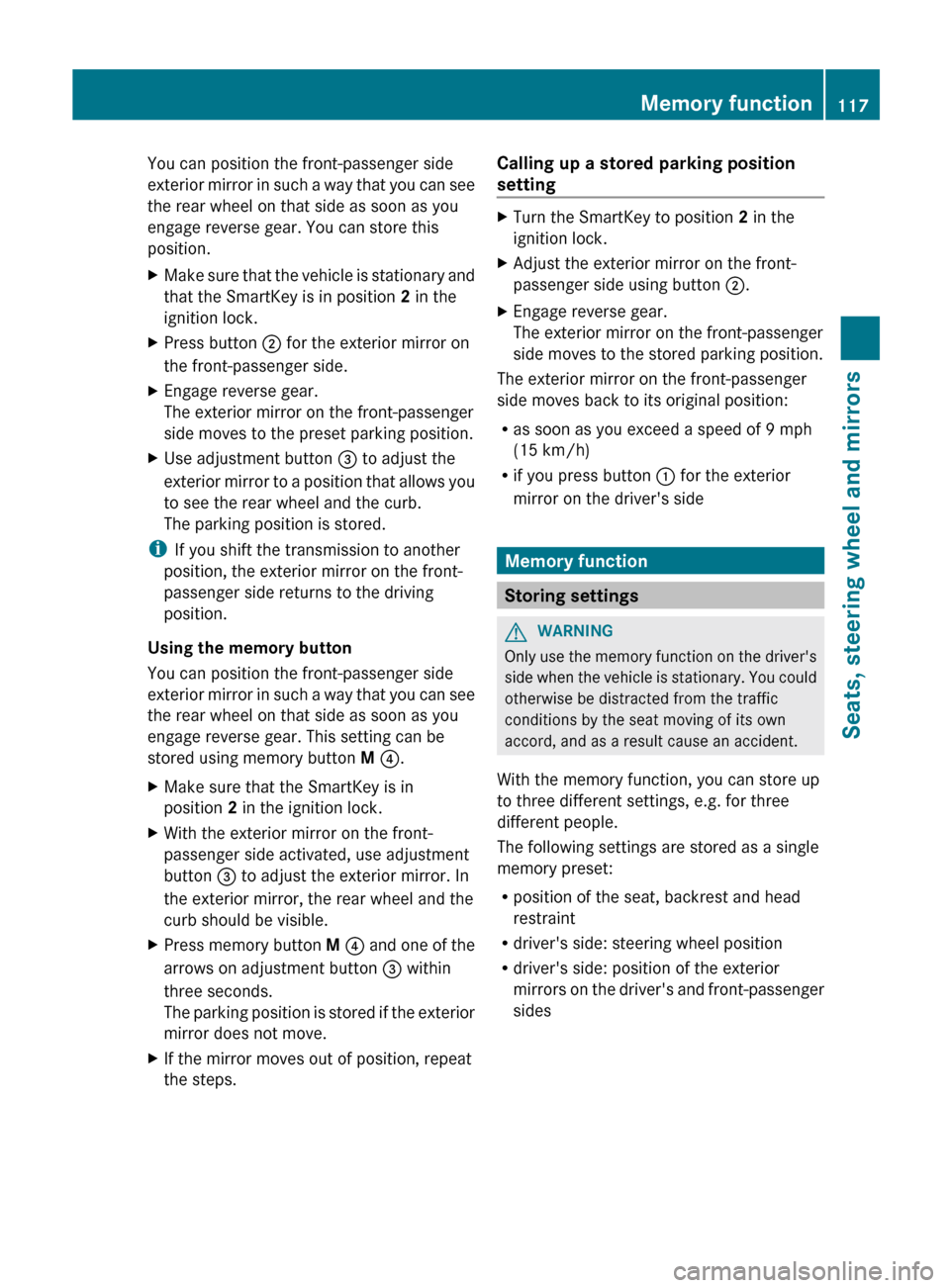
X Press button ; for the exterior mirror on
the front-passenger side.
X Engage reverse gear.
The exterior mirror on the front-passenger
side moves to the preset parking position.
X Use adjustment button = to adjust the
exterior
mirror to a position that allows you
to see the rear wheel and the curb.
The parking position is stored.
i If you shift the transmission to another
position, the exterior mirror on the front-
passenger side returns to the driving
position.
Using the memory button
You can position the front-passenger side
exterior
mirror in such a way that you can see
the rear wheel on that side as soon as you
engage reverse gear. This setting can be
stored using memory button M ?.
X Make sure that the SmartKey is in
position 2 in the ignition lock.
X With the exterior mirror on the front-
passenger side activated, use adjustment
button = to adjust the exterior mirror. In
the exterior mirror, the rear wheel and the
curb should be visible.
X Press memory button M ?
and one of the
arrows on adjustment button = within
three seconds.
The parking position is stored if the exterior
mirror does not move.
X If the mirror moves out of position, repeat
the steps. Calling up a stored parking position
setting X
Turn the SmartKey to position 2 in the
ignition lock.
X Adjust the exterior mirror on the front-
passenger side using button ;.
X Engage reverse gear.
The exterior mirror on the front-passenger
side moves to the stored parking position.
The exterior mirror on the front-passenger
side moves back to its original position:
R as soon as you exceed a speed of
9 mph
(15 km/h)
R if you press button : for the exterior
mirror on the driver's side Memory function
Storing settings
G
WARNING
Only use the memory function on the driver's
side
when the vehicle is stationary. You could
otherwise be distracted from the traffic
conditions by the seat moving of its own
accord, and as a result cause an accident.
With the memory function, you can store up
to three different settings, e.g. for three
different people.
The following settings are stored as a single
memory preset:
R position of the seat, backrest and head
restraint
R driver's side: steering wheel position
R driver's side: position of the exterior
mirrors on the driver's and front-passenger
sides Memory function
117
Seats, steering wheel and mirrors Z
Page 120 of 372

X
Adjust the seat ( Y page 108).
X On the driver's side, adjust the steering
wheel (Y
page 113) and the exterior mirrors
(Y page 115).
X Press memory button M and one of the
storage position buttons 1, 2 or 3 within
three seconds.
The settings are stored in the selected
preset position. A tone sounds when the
settings have been completed. Calling up a stored setting
X Press and hold the relevant storage
position button 1, 2 or 3 until the seat,
steering wheel and exterior mirrors are in
the stored position.
i The setting procedure is interrupted as
soon as you release the storage position
button. 118
Memory function
Seats, steering wheel and mirrors
Page 195 of 372
below the minimum, the distance may no
longer be shown.
Warning displays
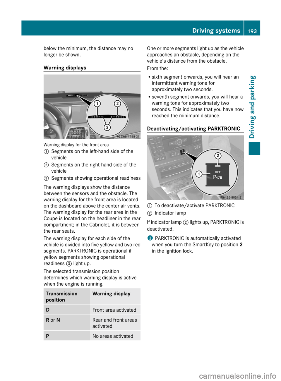
Warning display for the front area
:
Segments on the left-hand side of the
vehicle
; Segments on the right-hand side of the
vehicle
= Segments showing operational readiness
The warning displays show the distance
between the sensors and the obstacle. The
warning display for the front area is located
on
the dashboard above the center air vents.
The warning display for the rear area in the
Coupe is located on the headliner in the rear
compartment; in the Cabriolet, it is between
the rear seats.
The warning display for each side of the
vehicle is divided into five yellow and two red
segments. PARKTRONIC is operational if
yellow segments showing operational
readiness = light up.
The selected transmission position
determines which warning display is active
when the engine is running. Transmission
position Warning display
D
Front area activated
R or N Rear and front areas
activated
P
No areas activated One or more segments light up as the vehicle
approaches an obstacle, depending on the
vehicle's distance from the obstacle.
From the:
R
sixth segment onwards, you will hear an
intermittent warning tone for
approximately two seconds.
R seventh segment onwards, you will hear a
warning tone for approximately two
seconds. This indicates that you have now
reached the minimum distance.
Deactivating/activating PARKTRONIC :
To deactivate/activate PARKTRONIC
; Indicator lamp
If indicator lamp ;
lights up, PARKTRONIC is
deactivated.
i PARKTRONIC is automatically activated
when you turn the SmartKey to position 2
in the ignition lock. Driving systems
193
Driving and parking Z
Page 270 of 372

Useful information
i This Operator's Manual describes all
models and all standard and optional
equipment of your vehicle available at the
time of publication of the Operator's
Manual. Country-specific differences are
possible.
Please note that your vehicle may
not be equipped with all features
described. This also applies to safety-
related systems and functions.
i Read the information on qualified
specialist workshops: ( Y page 24).Stowage areas
Loading guidelines
G
WARNING
Always fasten items being carried as securely
as possible. Use cargo tie-down rings and
fastening
materials appropriate for the weight
and size of the load.
In an accident, during hard braking or sudden
maneuvers, loose items will be thrown around
inside the vehicle. This can cause injury to
vehicle occupants unless the items are
securely fastened in the vehicle.
To help avoid personal injury during a collision
or sudden maneuver, exercise care when
transporting cargo. Do not pile luggage or
cargo higher than the seat backrests.
The trunk is the preferred place to carry
objects.
Never drive a vehicle with the trunk open.
Deadly carbon monoxide (CO) gases may
enter vehicle interior resulting in
unconsciousness and death.
The handling characteristics of a laden
vehicle are dependent on the distribution of
the load within the vehicle. For this reason,
you should observe the following notes when
transporting a load:
R when transporting a load, never exceed the
maximum permissible gross vehicle weight or the gross axle weight rating of the
vehicle (including occupants). The values
are specified on the vehicle identification
plate on the B-pillar of the driver's door.
R position heavy loads as far forwards as
possible and as low down in the trunk as
possible.
R the
load must not protrude above the upper
edge of the seat backrests.
R always place the load against the rear or
front seat backrests. Make sure that the
seat backrests are securely locked into
place.
R always place the load behind unoccupied
seats if possible.
R secure the load with sufficiently strong and
wear-resistant tie-downs. pad sharp edges
for protection. Stowage space
Important safety notes G
WARNING
To help avoid personal injury during a collision
or sudden maneuver, exercise care when
storing objects in the vehicle. Put luggage or
cargo in the trunk if possible.
Do not pile luggage or cargo higher than the
seat backrests.
Keep compartment lids closed. This will help
to prevent stored objects from being thrown
about and injuring vehicle occupants during
R braking
R vehicle maneuvers
R an accident268
Stowage areas
Stowage and features
Page 328 of 372
Follow recommended tire inflation pressures
and check the pressure of all the tires
including the spare wheel:
R
monthly, at least
R if the load changes
R before beginning a long journey
R under different operating conditions, e.g.
off-road driving
If necessary, correct the tire pressure.
i The
specifications on the sample Tire and
Loading Information placard and tire
pressure tables are examples. Tire
pressure specifications are vehicle-specific
and may deviate from the data shown here.
The tire pressure specifications that are
valid for your vehicle can be found on the
Tire and Loading Information placard and
tire pressure table on the vehicle.
General notes The recommended tire pressures for the tires
mounted at the factory can be found on the
labels described here.
Operation with the emergency spare
wheel
(Y page 355).
Further information on tire pressures can be
obtained at a qualified specialist workshop.
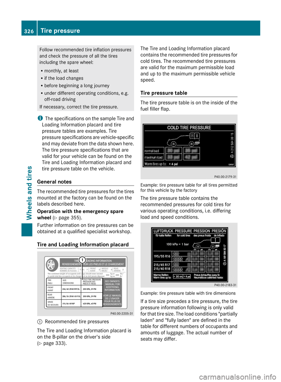
Tire and Loading Information placard :
Recommended tire pressures
The Tire and Loading Information placard is
on the B-pillar on the driver's side
(Y page 333). The Tire and Loading Information placard
contains
the recommended tire pressures for
cold tires. The recommended tire pressures
are valid for the maximum permissible load
and up to the maximum permissible vehicle
speed.
Tire pressure table The tire pressure table is on the inside of the
fuel filler flap.
Example: tire pressure table for all tires permitted
for this vehicle by the factory
The tire pressure table contains the
recommended pressures for cold tires for
various operating conditions, i.e. differing
load and speed conditions.
Example: tire pressure table with tire dimensions
If
a tire size precedes a tire pressure, the tire
pressure information following is only valid
for that tire size. The load conditions "partially
laden" and "fully laden" are defined in the
table for different numbers of occupants and
amounts of luggage. The actual number of
seats may differ. 326
Tire pressure
Wheels and tires
Page 336 of 372

X
Specification for maximum gross vehicle
weight : is listed in the Tire and Loading
Information
placard: "The combined weight
of occupants and cargo should never
exceed XXX kilograms or XXX lbs."
The gross weight of all vehicle occupants,
load and luggage must not exceed the
specified value.
i The specifications shown on the Tire and
Loading Information placard in the
illustration are examples. The maximum
permissible gross vehicle weight rating is
vehicle-specific
and may differ from that in
the illustration. You can find the valid
maximum permissible gross vehicle weight
rating for your vehicle on the Tire and
Loading Information placard. Number of seats
Maximum number of seats
: indicates the
maximum number of occupants allowed to
travel in the vehicle. This information can be
found on the Tire and Loading Information
placard.
i The specifications shown on the Tire and
Loading Information placard in the
illustration are examples. The number of
seats
is vehicle-specific and can differ from
the details shown. The number of seats in
your vehicle can be found on the Tire and
Loading Information placard. Determining the correct load limit
Step-by-step instructions The following steps have been developed as
required of all manufacturers under Title 49,
Code of U.S. Federal Regulations, Part 575
pursuant to the "National Traffic and Motor
Vehicle Safety Act of 1966".
X
Step 1: Locate the statement "The
combined weight of occupants and cargo
should
never exceed XXX kg or XXX lbs." on
your vehicle’s Tire and Loading Information
placard.
X Step 2:
Determine the combined weight of
the driver and passengers that will be riding
in your vehicle.
X Step 3: Subtract the combined weight of
the driver and passengers from XXX
kilograms or XXX lbs.
X Step 4: The resulting figure equals the
available
amount of cargo and luggage load
capacity. For example: at a sum “XXX” of
1400 lbs and five occupants each weighing
150 lbs, the amount of available cargo and
luggage load capacity is 650 lbs (1400 -
750 (5 x 150) = 650 lbs).
X Step 5:
Determine the combined weight of
luggage and cargo being loaded on the
vehicle. That weight may not safely exceed
the available cargo and luggage load
capacity calculated in step 4.334
Loading the vehicleWheels and tires
Page 346 of 372
Occupant distribution
The distribution of occupants in a vehicle at
their designated seating positions.
Total load limit
Rated cargo and luggage load plus
68 kilograms (150 lb) multiplied by the
number of seats in the vehicle.
Changing a wheel
Flat tire
You can find information on what to do in the
event of a flat tire in the "Breakdown
assistance" section (Y page 308).
Instructions for driving with MOExtended
tires in the event of a flat tire are also provided
there.
The "Breakdown assistance" section
(Y page 308) contains information and notes
on how to deal with a flat tire. Instructions for
driving with MOExtended tires in the event of
a flat tire are also provided there. Interchanging the wheels
G
WARNING
Interchanging the front and rear wheels may
severely impair the driving characteristics if
the
wheels or tires have different dimensions.
The wheel brakes or suspension components
may also be damaged. There is a risk of
accident.
Rotate front and rear wheels only if the wheels
and tires are of the same dimensions.
! On vehicles equipped with a tire pressure
monitor, electronic components are
located in the wheel.
Tire-mounting tools should not be used
near the valve. This could damage the
electronic components.
Only have tires changed at a qualified
specialist workshop. Always observe the instructions and safety
notes in the "Mounting a wheel" section
(Y page 345).
The wear patterns on the front and rear tires
differ,
depending on the operating conditions.
Rotate the wheels before a clear wear pattern
has formed on the tires. Front tires typically
wear more on the shoulders and the rear tires
in the center.
If your vehicle's tire configuration allows, you
can rotate the wheels according to the
intervals in the tire manufacturer's warranty
book in your vehicle documents. If this is not
available, the tires should then be replaced
every 3,000 to 6,000 miles (5,000 to
10,000 km), or earlier if the tire wear requires
this. Do not change the direction of wheel
rotation.
Clean the contact surfaces of the wheel and
the brake disc thoroughly every time a wheel
is interchanged. Check the tire pressure and,
if necessary, restart the tire pressure loss
warning system or the tire pressure monitor. Direction of rotation
Tires with a specified direction of rotation
have
additional benefits, e.g. if there is a risk
of hydroplaning. You will only gain these
benefits if the correct direction of rotation is
maintained.
An arrow on the sidewall of the tire indicates
its correct direction of rotation. Storing wheels
Store
wheels that are not being used in a cool,
dry and preferably dark place. Protect the
tires from oil, grease, gasoline and diesel. Cleaning the wheels
G
WARNING
The water jet from a circular jet nozzle (dirt
blasters)
can cause invisible exterior damage344
Changing a wheel
Wheels and tires
Page 362 of 372
Useful information
i This Operator's Manual describes all
models and all standard and optional
equipment of your vehicle available at the
time of publication of the Operator's
Manual. Country-specific differences are
possible.
Please note that your vehicle may
not be equipped with all features
described. This also applies to safety-
related systems and functions.
i Read the information on qualified
specialist workshops: ( Y page 24).Information regarding technical data
i The
data stated here specifically refers to
a vehicle with standard equipment. Consult
an authorized Mercedes-Benz Center for
the data for all vehicle variants and trim
levels. Genuine Mercedes-Benz parts
G
WARNING
Driving safety may be impaired if non-
approved parts, tires and wheels or safety-
relevant accessories are used.
This could lead to malfunctions in safety-
relevant
systems, e.g. the brake system. This
could cause you to lose control of your vehicle
and cause an accident.
For this reason, Mercedes-Benz recommends
that you use genuine Mercedes-Benz parts or
parts of equal quality. Only use tires, wheels
and accessories that have been specifically
approved for your vehicle. H
Environmental note
Daimler AG also supplies reconditioned major
assemblies and parts which are of the same
quality
as new parts. They are covered by the
same Limited Warranty entitlements as new
parts. !
Air bags and Emergency Tensioning
Devices, as well as control units and
sensors
for these restraint systems, may be
installed in the following areas of your
vehicle:
R doors
R door pillars
R door sills
R seats
R cockpit
R instrument cluster
R center console
Do not install accessories such as audio
systems in these areas. Do not carry out
repairs or welding. You could impair the
operating efficiency of the restraint
systems.
Have aftermarket accessories installed at
a qualified specialist workshop.
Genuine Mercedes-Benz parts are subject to
strict quality control. Each part has been
specially developed, manufactured or
selected for Mercedes-Benz vehicles and
fine-tuned for them. Only genuine Mercedes-
Benz parts should therefore be used.
More than 300,000 different genuine
Mercedes-Benz parts are available for
Mercedes-Benz models.
All Mercedes-Benz Centers maintain a supply
of genuine Mercedes-Benz parts for
necessary service and repair work. In
addition, strategically located parts delivery
centers provide quick and reliable parts
service.
Always specify the vehicle identification
number (VIN) ( Y page 361) and the engine
number (Y page 362) when ordering genuine
Mercedes-Benz parts. Warranty
Your
vehicle is covered under the terms of the
warranties printed in the Service and
Warranty Information booklet. 360
Warranty
Technical data